Abstract
In this paper authors carried out research, while modified gear fixing was used to limit the vibrations of the gearbox with non-parallel shaft axes. For tests modified back-to-back test stand was used. During test gearbox worked without load, with various rotational frequency and value of non-parallelism of shafts axes. Analysis of the obtained results presents that only in some cases the use of modified fixing of gear causes a reduction of the measured vibrations.
1. Introduction
In many drive systems gearboxes are one of the basic components. They are commonly used in construction of transmission systems of various vehicles, industrial machines or even aircrafts such as helicopters. Especially if transmission of torque and rotational speed with possibility of changing their value between input and output is required, gearboxes are one of the most popular way [1-3]. Unfortunately, gearboxes are not without drawbacks, to which belong vibrations generated during its operation. Generated vibrations affect the durability of the transmission components and undesirably affect their surroundings together with the accompanying noise. Many scientific studies aimed at reducing vibroactivity of gearboxes are continuously carried out [4-6]. The authors of these scientific works are looking for the possibility to limit generated vibrations in many areas, which include e.g.: the appropriate gearbox’s housing design, appropriate selection of lubricants used in the transmission, right choice of couplings parameters and bearings types [6-12].
The aforementioned searching areas for new possibilities to reduce generated by the transmission vibrations undoubtedly provide valuable data. Also, it should be noted, that one of the main vibrations sources are variable in time forces derived from meshing. Cooperating gears and load distribution along the contact line of their teeth are very important parameters affecting gearbox vibroactivity. Uneven load distribution on the meshing width can be a common problem due to random deviations of the gears and other transmission elements, or assembly errors of these elements, which may result in non-parallelism of shaft axes. In this paper authors presented results of research, while a modified gear fixing was used to limit the gearbox vibrations with non-parallel shaft axes.
2. Description of test stand and conducted research
For the tests a back-to-back stand was used, which was purposely modified. The following modifications were made: replacement of the driven gear shaft of the tested gear with a stationary axis, use of eccentric bushings to seat the stationary axis in the gearbox housing and enable to change the value of axes non-parallelism, disassembly of closing gearbox to eliminate additional stationary disturbances. During the research the tested gearbox was a kinematic transmission and did not transmit the torque. Two fitting methods of driven wheel on a stationary axis were used. First of them prevents the angular deflection of the axis of rotation of gear relative to the stationary axis (MS designation), second method enables angular deflection of the axis of rotation of gear relative to the stationary axis (MW designation).
Fig. 1Back-to-back test stand: 1 – tested gearbox; 2 – axis of drive gear (z2); 3 – stationary axis of driven gear (z1); 4 – eccentric bushing of bearing (Z1); 5 – sensor measuring vibration acceleration of the transmission housing at the point K; 6 – sensors measuring vibration acceleration of axis in a direction parallel to the action of the lateral force Fo (designation O1Z_FO) and parallel to the action of the radial force Fr (designation O1Z_FR)
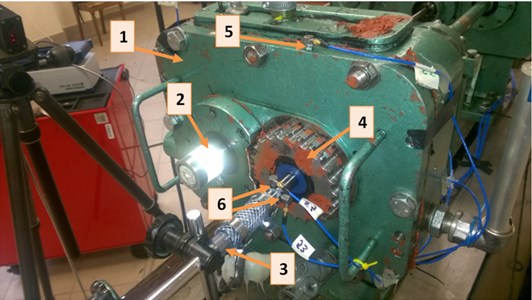
During the tests, the vibrations of gearbox housing was measured at the point K (Fig. 1), and the vibrations of stationary axis at point 6 (Fig. 1) at different positions of eccentric bushes as well as for different rotational frequencies of the drive gear . Piezoelectric vibration sensors were positioned in such way that enable the measurement of vibration accelerations in the direction parallel to the action of the lateral force and parallel to the action of the radial force .
3. Obtained results with analysis
Based on the vibration signals recorded during the tests in points K, O1_FO and O1_FR (Fig. 1 – 5, 6), their RMS values were calculated. Obtained RMS values are shown in diagram 2 for point K and diagrams 3, 4, 5 for points O1_FO, O1_FR. Results are presented as a function of representative bearing position Z1 for two selected rotational frequencies of drive gear .
Fig. 2The RMS values of the measured vibration signals in point K in the function of the bearing “Z1” position and the method of fixing the gear z1 on the stationary axis, rotational frequency of the gear z2 was fo2 = 20 Hz
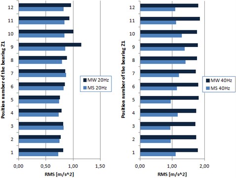
Fig. 3Spectrum of measured vibration signals in points O1_FO and O1_FR in two parallel directions
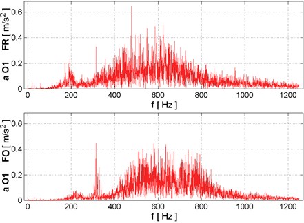
Fig. 4The RMS values of the measured vibration signals in points O1_FO and O1_FR in the function of the bearing “Z1” position and the method of fixing the gear z1, rotational frequencies of the gear z2 was fo2 = 20 Hz and fo2 = 40 Hz
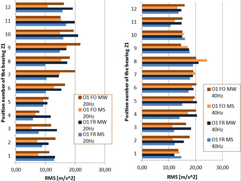
Fig. 5Sums of amplitudes of the first 4 harmonic of meshing frequencies obtained from the vibration signals measured in points O1_FO and O1_FR in the function of the bearing “Z1” position and the method of fixing the gear z1, rotational frequencies of the gear z2 was fo2 = 20 Hz and fo2 = 40 Hz
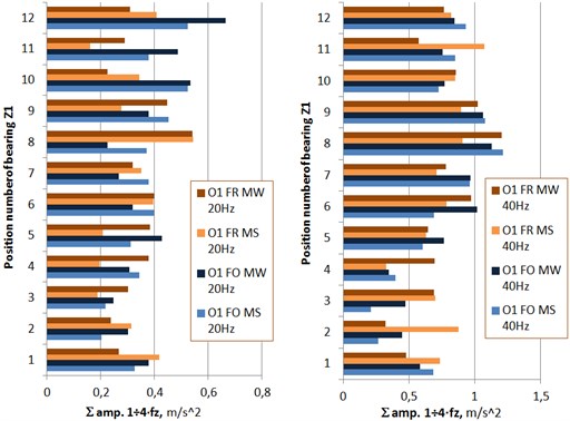
Gearboxes with spur gears very often generates vibrations signals, which frequency spectrum parts associated with the meshing frequency, and its harmonics have the largest amplitudes. This fact was taken into account and an indicator of the vibration level, as the sum of the amplitudes of the first 4 harmonics of the meshing frequency, was affiliate.
4. Conclusions
Provided that non-parallelism of the gearbox axes occurs, level of generated vibrations during gearbox operations changes and it is strongly connected with the relative positions of shafts.
For gearboxes, which operates unloaded for a long period of time, the use of gear fitting enabling angular deflection is not recommended. As shown in diagrams in Chapter 3, in a many cases application of the mentioned solution increases the RMS values of the vibration signals. For point K, which was placed at the gearbox’s housing, reduction of generated vibrations was unnoticeable.
In the case of the sum of the amplitudes of the first four harmonics of the meshing frequencies (Fig. 5), the fitting application enabling angular deflection of gear was beneficial in a large number of investigated cases. Due to the fact that the dominant amplitudes have the meshing frequency and its harmonics in event of gearbox with spur gear, the fitting application used in gear may create the possibility of reducing the effects caused by the non-parallelism of the axes of the transmission shafts.
References
-
Łazarz B. Identified dynamic model of the gearbox as the basis for design. Wydawnictwo i Zakład Poligrafii Instytutu Technologii Eksploatacji, Katowice-Radom, 2001, (in Polish).
-
Wilk A., Łazarz B., Madej H. Vibroactivity of gear transmissions. The influence of constructional features and wear of elements on the vibroactivity of drive systems with gear transmissions. Wydawnictwo Naukowe Instytut Technlogii Eksploatacji, Katowice-Radom, 2009, (in Polish).
-
Madej H. Minimization of vibroacoustic activity of gearboxes housings. Wydawnictwo i Zakład Poligrafii Instytutu Technologii Eksploatacji, Katowice-Radom, 2003, (in Polish).
-
Dogruer C. U., Pirsoltan A. K. Active vibration control of a single-stage spur gearbox. Mechanical Systems and Signal Processing, Vol. 85, 2017, p. 429-444.
-
Feng Z., Zuo M. J. Vibration signal models for fault diagnosis of planetary gearboxes. Journal of Sound and Vibration, Vol. 331, 2012, p. 4919-4939.
-
Grega R., Krajňák J., Žulová L., Fedorko G., Molnár V. Failure analysis of driveshaft of truck body caused by vibrations. Engineering Failure Analysis, Vol. 79, 2017, p. 208-215.
-
Shen A., Randall R. B. Optimal rib stiffening for noise reduction of constant speed gearboxes. 15th International Congress on Sound and Vibration, Korea, Daejeon, 2008.
-
Figlus T., Wilk A., Madej H. A study of the influence of ribs shape on the gear transmission housing vibroactivity. Transport Problems, Vol. 5, Issue 1, 2010, p. 63-69.
-
Grega R., Homišin J., Krajňak J., Urbanský M. Analysis of the impact of flexible couplings on gearbox vibrations. Scientific Journal of Silesian University of Technology, Series Transport, Vol. 91, 2016, p. 43-50.
-
Wojnar G., Minimization of dynamic forces in gear meshing by selection of the flexible couplings parameters. Journal of Kones. Powertrain and Transport, Vol. 17, Issue 3, 2010, p. 497-504.
-
Łazarz B., Peruń G., Influence of construction factors on the vibrational activity of the gearing. Transport Problems, Vol. 7, Issue 2, 2012, p. 95-102.
-
Wieczorek A. The role of lubrication in reducing noise associated with the operation of gearboxes. Mechanizacja i Automatyzacja Górnictwa, Vol. 478, Issue 12, 2010, p. 34-39, (in Polish).
About this article

