Abstract
Experiments on scour around multiple piles were carried out for several current and wave conditions: pile numbers were 1, 3, and 7; and wave only, current only, and current and wave flows. A moderate wave condition was chosen as the representative wave, which produced relatively small scour depth. A depth-average current speed was chosen as the representative current, which produced relatively large scour hole. When waves were superimposed on current, scour hole depth decreased. Existing the Sumer and Fredsøe’s prediction formula of scour hole depth for current and wave flows for multiple piles describes the present experimental results reasonably well.
1. Introduction
Scour around vertical structures can cause several engineering problems, e. g. reducing bearing capacity of the structure, or increasing tensions of relevant pipelines or cables attached to the structure. Prediction of scour focuses on either final equilibrium state, or time-evolving feature. For instance, the scour starts to develop when the structure is constructed until reaches equilibrium. Scour could keep on changing, if the surrounding flows change continuously like tidal flow.
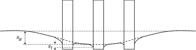
Equilibrium scour hole depth around vertical cylindrical structures for steady flow has been extensively studied through laboratory experiments or numerical experiments, and empirical formulas for prediction have been proposed by many researchers. In study of Sumer and Fredsøe [1], the Keulegan-Carpenter number has proven to be the dominant variable deciding the equilibrium scour depth. Sumer et al. [2] studied scour around vertical pile in wave. In that study, the results of an experimental measuring on scour around piles were presented. Also based on their data, a design equation was established, relating the scour depth to the Keulegan-Carpenter number. When multiple piles are constructed, scour hole depths are affected by the number of the piles as well as the dimensions of the mono pile due to enhanced turbulence generated by many piles. The additional influence of scour depth has been accounted by the ratio between the gap width and the pile diameter (Sumer and Fredsøe [3]). However, it is presumed that the above ratio of the gap width over the pile diameter may not be sufficient for prediction of the overall scour hole depth. The number of piles or the total area of the multiple piles may influence the group-related scour depth, . is the group-related scour depth, and is the local scour depth, see Fig. 1.
Fig. 1Scour depth group-related and local scour depth
It may be meaningful to investigate the effect of the number of piles with the same ratio of the gap over the pile diameter, while keeping all the other parameters identical.
2. Experiment design
In order to distinguish the effect of multiplicity of piles explicitly, experimental cases were carefully designed for the present study. We intend to extract the effect of pile numbers, while keeping all the other variables steady.
Typical three flow conditions were chosen as representative flow environments: wave only, current only, and current and wave coexisting flows. It could be expected that these cases may not cover wide range of flow situation, but reveal the characteristics of the scour with multiple piles.
The two-dimensional flume at Kookmin University, Seoul, Korea was used: 0.8 m wide, 1.0 deep, and 23 m long. The flume includes panel-type wave generator, and reversible current generating pump, see Fig. 2.
The water depth was maintained 0.5m at centre of sandy bed, and the circular vertical pile diameter was 10 cm. the gap width ratio for both 3 and 7 piles were 2, see Fig. 3.
Fig. 2Experimental model and current and wave direction
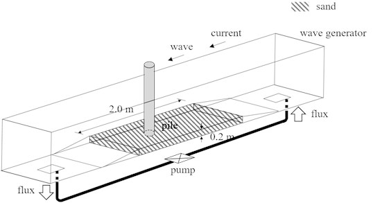
Fig. 3Floor plan of experimental case for the number of piles
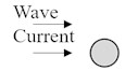
a) Single pile
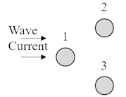
b) 3 piles
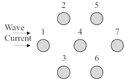
c) 7 pile
Bed material should be chosen to represent field conditions. Considering west coast of Korea, where bed material is mainly sand along main tidal channels, and mixed sand and silt around shaded zones. Median sand diameter is between 100-300 on the west coast of Korea. Applying the length scale of model over prototype of 1/40, and Froude similarity, could be applied to the settling velocity. Then, the adequate sand median diameter should be 80, which was used for the present experiments.
The sandy bed was prepared within 2.0 m length between two transitional steps, see Fig. 2. The sand depth was 20 cm, which may be sufficiently deep for possible scour due to waves and currents.
In order to distinguish the effect of the total pile number on the total scour depth, a typical wave condition needs to be chosen, so that it is applied to most experimental cases.
In study of Sumer and Fredsøe [1], the Keulegan-Carpenter number has proven to be the variable dominating the equilibrium scour depth:
where is the undisturbed linear near-bed orbital velocity amplitude, is the wave period, and is the pile diameter.
Keulegan-Carpenter number is known as a dimensionless quantity describing the relative importance of the drag forces over inertia forces for bluff objects in an oscillatory fluid flow.
We choose a monochromatic wave train of period 1.5 s, and 10 cm amplitude on the water depth of 0.5 m, which results in KC of 2.5, which implies waves are large to produce scour around piles. The fact that the KC number does not reflect information on the bed material like median bed size, implies that the scour hole depths are strongly controlled by the structural dimension, if the flow speed is above a threshold value.
Preliminary experiments demonstrate bedform existence for a range of current speeds. Depth-average current velocity of 50 cm/s produces large bed shear stress, and consequent scour holes. Depth-average current velocity was kept on 0.5 cm/s by adjusting the flow rate meter, for current only cases and current and wave cases.
The experimental cases were designed as combinations of 3 flow cases and 3 pile alignments cases, i.e. current, wave, current/wave flows, multiplied by single, 3, and 7 piles cases; i.e. 9 cases altogether.
3. Results
The experiment results of the scour depths are shown in the following tables.
Table 1Measured scour depth for single pile
Case number | Condition | Scour depth (cm) |
1 | Current only | 7.2 |
2 | Wave only | 0.3 |
3 | Current and Wave | 6.9 |
Table 2Measured scour depth for 3 group piles
Case number | Condition | Pile | Scour depth (cm) |
4 | Current only | 1 | 8.5 |
2 | 9.6 | ||
3 | 10.3 | ||
Average | 9.5 | ||
5 | Wave only | 1 | 1.7 |
2 | 1.9 | ||
3 | 0.9 | ||
Average | 1.5 | ||
6 | Current and Wave | 1 | 7.3 |
2 | 8.7 | ||
3 | 8.9 | ||
Average | 8.3 |
First, the scour depth of Case 1 for current only and single pile was 7.2 cm, which is 0.72 times the pile diameter.
The scour depth of Case 2 for wave only and single pile was 0.3 cm, which is much smaller than that of current only case (Case 1). The wave orbital velocity near bed is 17.7 cm/s, and is thought to be comparable with the depth-average current speed of 0.5 m/s. small scour depth for their case could be understood as periodically reversing flow behaviors.
Table 3Measured scour depth for 7 group piles
Case number | Condition | Pile | Scour depth (cm) |
7 | Current only | 1 | 11.9 |
2 | 12.2 | ||
3 | 10.7 | ||
4 | 12.8 | ||
5 | 11.9 | ||
6 | 13.3 | ||
7 | 13.2 | ||
Average | 12.3 | ||
8 | Wave only | 1 | 2.5 |
2 | 2 | ||
3 | 1.9 | ||
4 | 2.4 | ||
5 | 2.7 | ||
6 | 2.3 | ||
7 | 2.2 | ||
Average | 2.3 | ||
9 | Current and Wave | 1 | 11.7 |
2 | 11.9 | ||
3 | 9.4 | ||
4 | 12.5 | ||
5 | 12.4 | ||
6 | 12.9 | ||
7 | 12.8 | ||
Average | 11.9 |
The scour depth of Case 3 for current and wave flow and single pile was 6.9 cm, which is slightly smaller than that of for current only case. It is thought that the instantaneous friction bed shear stress around scour hole may exceed a limiting value dividing the normal flow and sheet flow.
The scour depth of Case 4 current only flow and 3 piles was 9.5 cm on average, larger than those for single pile case, Case 1. The scour depth of Case 7, current only flow and 7 piles was 12.3 cm on average, larger than those for single pile case, and 3 piles case.
The scour depth of Case 5 wave only and 3 piles was 1.5 cm on average, larger than those for single pile case, Case 1. The scour depth of Case 8 wave only and 7 piles was 2.3 cm on average, larger than those for single pile case, and 3 piles case.
The scour depth of Case 6 current and wave and 3 piles was 8.3 cm on average, larger than those for single pile case, Case 3. The scour depth of Case 9 current and wave and 7piles was 11.9 cm average, larger than those for single pile case and 3 piles case, see Figs. 4-6.
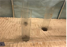
Fig. 4Photo of single pile experiment result
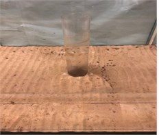
a) Wave
b) Current
c) Current and wave
This paper in case of group pile, the scour depth for each pile was averaged and compared. Sumer et al. [2] and Sumer and Fredsøe’s parameter [4] used for compared experimental scour depth with the theoretical scour depth.
Sumer et al. [2]:
In case of current and wave case, the scour depth is a function of the number and the parameter . Sumer and Fredsøe introduced defined as:
Sumer and Fredsøe’s parameter [4]:
where is the maximum value of orbital velocity of water particles at bed, and is the current velocity at distance of D/2 from bed.
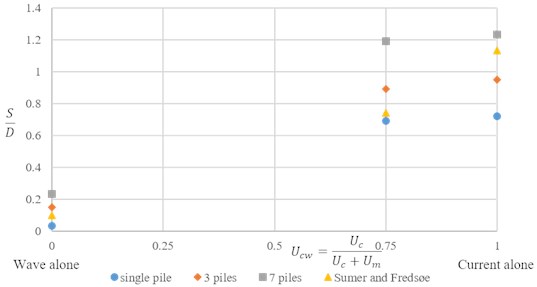
For comparison, the scour depth was non-dimensionalized by . Compare Sumer and Fredsøe formula with experimental result. The results are as follows, see Fig. 4.
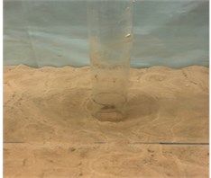
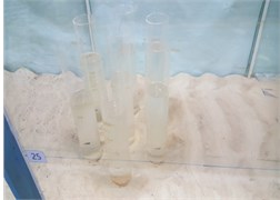
Fig. 5Photo of 3 group piles experiment result
a) Wave
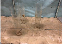
b) Current
c) Current and wave
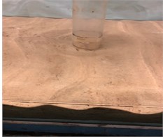
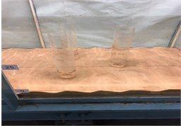
Fig. 6Photo of 7 group piles experiment result
a) Wave
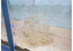
b) Current
c) Current and wave
Fig. 7Experimental scour depth and theoretical scour depth (S/D)
In cases of wave alone, was not much difference compared to result. Therefore, current cases and current and wave cases were compared. The Fig. 8(a), (b) are of Sumer and Fredsøe result and experimental result in current only flow and current and wave, see Fig. 8.
Fig. 8Scour depth of according to number of piles
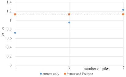
a) Current only
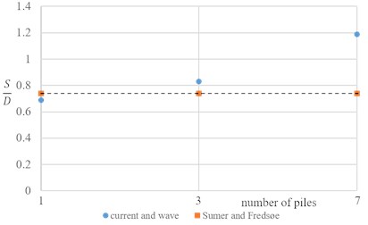
b) Current and wave
4. Conclusions
Experiment exhibited that the pile number increase the total scour depth, for the same gap over diameter ratio.
Experimental results demonstrate that the scour depths were small for wave only flows. Results also demonstrate that the scour depths for current and wave flows are slightly smaller or equal to those for current only flows. These results imply that the experimental conditions adopted include phases which may result in the sheer flow condition due to added reversing wave flows.
The conditions in the present experiments don’t cover all field environment. However, it is hoped that the flow and sediment conditions of their experiment represent a typical environment of the west coast of Korea. Wider range of conditions are recommended for real field design purposes.
For single pile cases, the scour occurred just around pile. However, for group piles cases, scour developed deeper than single pile, and scour was wider. Moreover, the larger the number of piles, the deeper the total depth of scour.
References
-
Sumer B. M., Fredsøe J. Scour below pipelines in waves. Journal of Waterway, Port, Coastal, Ocean Engineering, ASCE, Vol. 116, Issue 3, 1990, p. 307-323.
-
Sumer B. M., Fredsøe J., Christiansen N. Scour around vertical pile in waves. Journal of Waterway, Port, Coastal, Ocean Engineering, ASCE, Vol. 118, Issue 1, 1992, p. 15-31.
-
Sumer B. M., Fredsøe J. Wave scour around group of vertical piles. Journal of Waterway, Port, Coastal, Ocean Engineering, ASCE, Vol. 124, Issue 5, 1998, p. 248-256.
-
Sumer B. M., Fredsøe J. Scour around pile in combined waves and currents. Journal of Hydraulic Engineering, ASCE, Vol. 127, Issue 5, 2001, p. 403-411.
About this article

This work has been funded as a Research Project, “Installation and Corroborative Study for Internal Power Network of Ocean Wind Power Plant”, by Korea institute of Energy Technology Evaluation and Planning (KETEP) since 2015.
