Abstract
The paper presents a mathematical relation to express the effects of a T-shaped crack on beam-like structures. The study is performed by using the finite element method (FEM) and contrived analytical formulas for proving the existing correlation between deflection, strain energy, and natural frequency changes. The damaged beam static and dynamic behaviors are analyzed by means of the FEM. The frequency shift for the first mode of vibration derived directly was compared with the frequency alteration calculated involving the change in the beam deflection for several scenarios of the T-shaped crack. The frequency shift is derived using the relations between deflection and natural frequency. As the final step in the research, we compared the outcomes for the same crack with the results achieved from a beam suffering a loss of stiffness.
1. Introduction
Damages can modify both the physical properties of a structure (mass, stiffness) as well as its dynamic characteristics (natural frequencies, damping ratio, and modal shapes and curvature). The stiffness loss reduces the capacity of a structure to store energy, and it directly depends on the position [1-4], respectively on the shape and depth of the crack [5-8]. The theory was also developed for changing environment [9-11], variable beam cross-section [12] and multiple cracks [13, 14].
In previous studies [15-18], the authors developed a robust method for detecting, locating and evaluating transverse cracks in all types of beams, regardless of the constraining method, based on the natural frequency changes.
This paper presents a numerical study destined to find the dynamic response of beams with T-shaped cracks, in particular, the effect of the depth and position of the transverse crack component, using both analytical and FEM simulation methods.
2. Materials and methods
The research focuses on finding the effect of a branched crack on the natural frequencies of beam-like structures. To this aim, a steel beam, fixed on the left end and free at the other one (i.e. a cantilever beam) is considered in the study. It has the following key dimensions: the length 1000 mm, the width 50 mm and the thickness 5 mm. hence, the intact beam has a cross-sectional area and the moment of inertia 52083.33 mm4.
Table 1Physical-mechanical properties of the structural steel as defined in the ANSYS library
Mass density [kg/m3] | Young modulus [N/m2] | Poisson ratio | Tensile strength [MPa] | Yield strength [MPa] | Min. elongation [%] |
7850 | 2·1011 | 0.3 | 470-630 | 355 | 20 |
The relevant physical-mechanical properties, presented in Table 1, are extracted from the ANSYS library for a structural steel.
For the cantilever beam, the damage geometry is described as a T-shaped crack, resulted from a transverse component followed by a longitudinal branch, with its general dimensions presented in Fig. 1.
Fig. 1The geometry of a branched crack of ,,T” shape
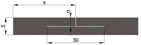
The transverse component extends from the upper surface of the beam to the longitudinal crack. We considered 5 different scenarios, by studying the effects of different depths ,,” of the T-shaped crack, starting from the upper surface of the beam 0.5 mm and further increasing it with a step of 0.5 mm until it reaches 2.5 mm, as illustrated in Fig. 1.
2.1. The finite element model of the test structure
In order to obtain the natural frequency and deflection of the damaged cantilever beam, two types of studies have been carried out, having the boundary conditions for the fixed end at the left extremity of the analyzed beam imposed by applying the fixed support constraint. For the static analysis, we applied a gravitational acceleration of 9.806 m/s2.
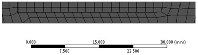
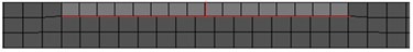
The intact beam was meshed by using hexahedral elements of maximum 2 mm size, resulting in a model containing 39501 elements and 197961 nodes. As illustrated in Fig. 2 for the crack depth 0.5, 1 and 1.5 mm, for the beam with T-shaped crack at the different depth, the resulted mesh is even finer because the elements are deformed in the interface between the intact beam and damage boundary.
Fig. 2a) a zoom on the left beam end for the intact beam, b)-d) the damaged beam, highlighting the prismatic element’s distribution
a)
b)
c)
d)
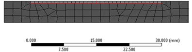
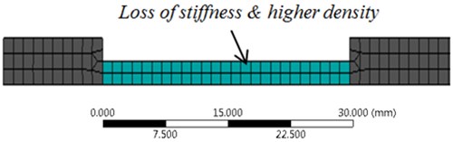
In addition, the defect location, for all damage cases was replaced by a segment of reduced thickness , thus a smaller stiffness (see Fig. 3). To compensate for the loss of mass we increased the mass density of the segment to 15700 kg/m3.
Fig. 3A zoom on the segment with a reduced thickness
2.2. The finite element model of the test structure
The static and dynamic characteristics of the cantilever beam where studied by means of finite element analysis with the ANSYS software, for all damage scenarios positioned at the distance 35 mm and at 500 mm from the fixed end, resulting in a number of 22 studies, including the undamaged beam analysis. Two types of simulations where performed, by using:
• Modal module for determining the natural frequencies for the cantilever beam for the first six weak axis bending modes.
• Static structural for determining the deflection of the beam at the free end.
In this study, we iteratively increase the depth of the crack’s transversal component by a step 0.5 mm, starting from the upper surface of the cantilever and evolving to the beam center. The first location of the damage is at position 35 mm, and further, we analyzed the effect of the damage placed at 500 mm from the fixed end. The beam with the reduced cross-section, nominated herein as the beam with a gap, is also implied in this study. The deflection increase at the cantilever beam’s free end due to damage, for the beam statically loaded with its own mass, and the natural frequencies are acquired.
From paper [15], the beam’s free end deflection for the healthy and damaged state is expressed by the mathematical relations:
The natural frequencies for the undamaged cantilever beam are given in accordance to the Euler-Bernoulli theory [11] with the relation:
From Eq. (1) and (2) we obtain:
After substituting Eq. (4) and (5) in Eq. (3), one obtains:
The natural frequency of the damaged beam results, from Eq. (6) and Eq. (7), as:
where is the correction coefficient.
In consequence, the relation of the normalized frequency shift can be found as:
which is, in fact, the damage severity derived for the crack located at the fixed end of the beam.
Knowing the deflection of the free end for both healthy and damaged beam, we calculated the correction coefficient and afterwards the frequency of the damaged beam in respect to the natural frequency of the intact beam, in accordance to Eq. (8). The results were compared with the frequencies of the damaged beam obtained directly from the FEM analysis, in order to prove that the correction coefficient and the severity can be used also for T-shaped cracks.
3. Results and discussions
To determine the correlation between the dynamic response and the changes in the deflection of cantilever beams, which occur due to different damage depth and positions, we compared the frequency changes obtained through modal analysis and the results calculated with Eq. (8) supported by static analysis for a crack with an inverted T-shape. Afterwards, we compared, the T-shaped crack with the results achieved from a beam having a rectangular gap with the fundamental dimensions as following: depth 0.5, ..., 2.5 mm increased iteratively by a step 0.5 mm and the longitudinal extend 30 mm, equal to that of the crack.
The correction coefficient is calculated from the deflection at the free end of the cantilever beam derived by means of the FEM. The natural frequency changes for the first weak-axis vibration mode are compared to those obtained by employing the Hybrid method, hence by applying the correction coefficient in Eq. (8). The results, as well as the attained errors, are presented in Table 2.
Table 2Comparison of frequencies obtained from FEM and calculated involving the Hybrid method
[mm] | [mm] | [mm] | [mm] | [-] | [Hz] | [Hz] | [Hz] | Error [%] |
35 | 0.5 | 22.948 | 23.864 | 0.9806 | 4.088 | 4.0101 | 4.0088 | 0.03 |
1 | 24.532 | 0.9671 | 3.8914 | 3.8913 | 0.00 | |||
1.5 | 24.031 | 0.9772 | 3.7155 | 3.7174 | 0.05 | |||
2 | 32.031 | 0.8464 | 3.4548 | 3.4602 | 0.16 | |||
2.5 | 40.295 | 0.7546 | 3.0747 | 3.0850 | 0.33 | |||
500 | 0.5 | 23.076 | 0.9972 | 4.0795 | 4.0766 | 0.07 | ||
1 | 23.281 | 0.9928 | 4.0628 | 4.0587 | 0.10 | |||
1.5 | 23.619 | 0.9856 | 4.0357 | 4.0295 | 0.15 | |||
2 | 24.215 | 0.9734 | 3.9889 | 3.9796 | 0.23 | |||
2.5 | 25.368 | 0.9511 | 3.8844 | 3.8881 | 0.10 |
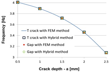
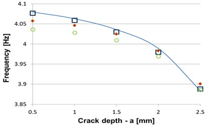
Additionally, we compared the modal FEM analysis and calculated results of the different damage position with that of the gap study. The results are presented in Table 3. The diagram obtained employing both the FEM and the hybrid FEM-analytical methods are presented in Fig. 4 for crack position at 35 mm and for 500 mm, respectively.
From Table 3 and from the Fig. 4 one can observe that comparing the frequencies obtained directly from FEM and calculated involving the hybrid FEM-analytical method for a T-shaped crack positioned near the fixed end and afterwards at the center of the beam, the errors are less that 0.33 %. The extremely small errors proved the precision achieved by using the correction coefficient and qualifies the method for prediction of frequency changes due to T-shaped cracks with known parameters.
Table 3Comparison of frequencies obtained from FEM simulation and Hybrid method for the T-shaped crack and the beam with a gap
[mm] | [mm] | FEM | Hybrid | ||||
[Hz] | [Hz] | Error [%] | [Hz] | [Hz] | Error [%] | ||
35 | 0.5 | 4.0086 | 4.0088 | 0.04 | 4.0072 | 4.009 | 0.04 |
1 | 3.889 | 3.8913 | 0.06 | 3.8888 | 3.891 | 0.06 | |
1.5 | 3.7126 | 3.7174 | 0.08 | 3.7145 | 3.717 | 0.08 | |
2 | 3.4517 | 3.4602 | 0.09 | 3.4570 | 3.460 | 0.09 | |
2.5 | 3.0689 | 3.0850 | 0.19 | 3.0791 | 3.085 | 0.19 | |
500 | 0.5 | 4.057 | 4.0766 | 0.55 | 4.0364 | 4.077 | 1.00 |
1 | 4.046 | 4.0587 | 0.42 | 4.0284 | 4.059 | 0.75 | |
1.5 | 4.0244 | 4.0295 | 0.28 | 4.0093 | 4.030 | 0.50 | |
2 | 3.983 | 3.9796 | 0.15 | 3.9691 | 3.980 | 0.26 | |
2.5 | 3.9006 | 3.8881 | 0.42 | 3.8861 | 3.888 | 0.05 | |
Fig. 4Comparison of frequencies obtained by FEM modal analysis and involving the hybrid method at crack position a) x= 35 mm and b) x= 500 mm
a)
b)
Table 3 shows that the beam with a gap instead of the T-shaped crack can substitute the crack in modeling the dynamic behavior of damaged beams. The error noticed here is less than 0.2 %, if the crack is present near the fixed end of the beam. For the crack positioned at 500 mm from the fixed end the maximum error is 1 %, showing that even if the error is larger than the previous study, the method still qualifies as a reliable damage indicator.
4. Conclusions
This paper presents the correlation between deflection, strain energy and natural frequency changes for beam-like structures by involving original mathematical relations. The methods presented show that the beams diminished capacity to store energy due to a crack through simple static analysis is a precise damage severity indicator. It was also proved that this indicator can be used even if the damage is not located at the position where the bending moment achieves maxima. Following, the effect of damage location was analyzed and it was shown that, if the crack is not located in the slice where the bending moment achieves maxima, its effect on the natural frequency changes is diminished in concordance to the normalized square of the mode shape curvature of the damaged slice in the intact state.
References
-
Sinha J. K., Friswell M. I., Edwards S. Simplified models for the location of cracks in beam structures using measured vibration data. Journal of Sound and Vibration, Vol. 251, Issue 1, 2002, p. 13-38.
-
Sakaris C. S., Sakellariou J. S., Fassois S. D. Vibration-based multi-site damage precise localization via the functional model based method. Procedia Engineering, Vol. 199, 2017, p. 2072-2077.
-
Gillich G. R., Gillich N., Birdeanu E. D., Iancu V. Detection of damages in simple elements. Annals of DAAAM and Proceedings of the International DAAAM Symposium, Vol. 20, 2009, p. 623-624.
-
Song Y. Z., Bowen C. R., Kim A. H., Nassehi A., Padget J., Gathercole N. Virtual visual sensors and their application in structural health monitoring. Structural Health Monitoring, Vol. 13, Issue 3, 2014, p. 251-264.
-
Chondros T. J., Dimarogonas A. D., Yao J. A continuous cracked beam vibration theory. Journal of Sound and Vibration, Vol. 215, Issue 1, 1998, p. 17-34.
-
Ostachowicz W. M., Krawczuk C. Analysis of the effect of cracks on the natural frequencies of a cantilever beam. Journal of Sound and Vibration, Vol. 150, Issue 2, 1991, p. 191-201.
-
Gillich G. R., Tufoi M., Korka Z. I., Stanciu E., Petrica A. The relations between deflection, stored energy and natural frequencies, with application in damage detection. Romanian Journal of Acoustics and Vibration, Vol. 13, Issue 2, 2016, p. 87-93.
-
Rizos P. F., Aspragathos N., Dimarogonas A. D. Identification of crack location and magnitude in a cantilever beam from the vibration modes. Journal of Sound and Vibration, Vol. 138, Issue 3, 1990, p. 381-388.
-
Worden K., Sohn H., Farrar C. R. Novelty detection in a changing environment: regression and interpolation approaches. Journal of Sound and Vibration, Vol. 258, Issue 4, 2002, p. 741-761.
-
Gillich G. R., Furdui H., Wahab M. A., Korka Z. I. A robust damage detection method based on multi-modal analysis in variable temperature conditions. Mechanical Systems and Signal Processing, Vol. 115, 2019, p. 361-379.
-
Hios J. D., Fassois S. D. A global statistical model based approach for vibration response-only damage detection under various temperatures: a proof-of-concept study. Mechanical Systems and Signal Processing, Vol. 49, Issues 1-2, 2014, p. 77-94.
-
Altunışık A. C., Okur F. Y., Kahya V. Modal parameter identification and vibration based damage detection of a multiple cracked cantilever beam. Engineering Failure Analysis, Vol. 79, 2017, p. 154-170.
-
Zhang K., Yan X. Multi-cracks identification method for cantilever beam structure with variable cross-sections based on measured natural frequency changes. Journal of Sound and Vibration, Vol. 387, 2017, p. 53-65.
-
Du Z., Chen X., Zhang H., Zi Y., Yan R. Multiple fault separation and detection by joint subspace learning for the health assessment of wind turbine gearboxes. Frontiers of Mechanical Engineering, Vol. 12, Issue 3, 2017, p. 333-347.
-
Gillich G. R., Maia N. M. M., Mituletu I. C., Tufoi M., Iancu V., Korka Z. I. A new approach for severity estimation of transversal cracks in multi-layered beams. Latin American Journal of Solids and Structures, Vol. 13, Issue 8, 2016, p. 1526-1544.
-
Gillich G. R., Mituletu I. C., Praisach Z. I., Negru I., Tufoi M. Method to enhance the frequency readability for detecting incipient structural damage. Iranian Journal of Science and Technology, Transactions of Mechanical Engineering, Vol. 41, Issue 3, 2017, p. 233-242.
-
Mituletu I. C., Gillich N., Nitescu C. N., Chioncel C. P. A multi-resolution based method to precise identify the natural frequencies of beams with application in damage detection. DAMAS 2015 – Journal of Physics: Conference Series, Vol. 628, Issue 1, 2015, p. 12020.
-
Gillich G. R., Praisach Z. I., Iancu V., Furdui H., Negru I. Natural frequency changes due to severe corrosion in metallic structures. Strojniški vestnik – Journal of Mechanical Engineering, Vol. 61, Issue 12, 2015, p. 721-730.
About this article

