Abstract
The use of automatic balancing devices in unbalanced rotor systems has proven their ability to reduce rotor vibrations in the super resonance zone of velocities. At the same time, the creation of efficient automatic balancing devices with a torus-shaped body and a circular cross-section is associated with the multimodal motion of the compensating masses, which makes the device unsuitable for operation. To ensure the acceleration of the compensating masses from the rest state to the working speed of the rotor, they need to be provided with some initial velocity. The magnitude of this velocity is influenced by the parameters of the elastic suspension of the rotor, the geometric parameters of the automatic balancing device, the rolling friction coefficient between the body and the compensating mass, etc. The work is devoted to the description of the vertical rotor model with an automatic balancer with two compensating masses. It also considers the effect of the rolling friction coefficient on the value of their initial velocity.
1. Introduction
To reduce the unbalance of the rotating unbalanced rotor in the super resonant frequency band, automatic balancing devices (hereinafter ABD) mounted on the rotor can be used. This is especially topical when the magnitude of the imbalance is random, for example, in grinding devices, centrifuges, etc. As noted in [1], the ball-type ABD with a circular cross-section has the greatest sensitivity as the compensating mass (hereinafter CM) in this case has one point of contact with the body of the ABD. At the same time, a reduced resistance force and an increase in the degree of freedom of the CM lead to a multimode of the ABD in the transient mode of accelerating the CM to the working speed of the rotor. In [2, 3], the influence of the damping forces of the rotor system on the acceleration of the CM in the ring of the rectangular cross-section of the ABD is considered, therefore it is of interest to consider the acceleration of the CM in a body with a circular cross-section of an ABD under the action of rolling friction between the CM and the ABD’s body.
It is of interest to determine the dependence of the magnitude of the absolute initial velocity of the CM on the value of the rolling friction coefficient between these masses and the ABD’s body. In the case when the CMs steadily move relative to the ABD’s body, the rotor has increased vibrations [4, 5]. The results of the work can be used in the design and calculation of ball-type ABDs with a torus-shaped body.
The aim of the work is to describe the mathematical model of a vertical rotor with a ball-type ABD and a torus-shaped body and a circular cross-section with two CMs. The work is a continuation of work [1] and is based on experimental tests of a rotor with an ABD [6].
2. Calculation scheme and mathematical model of a rotor with an ABD
The paper deals with a symmetrical vertical rigid rotor on an elastic-dissipative suspension and with an ABD. The ABD’s body is made of a toroidal shape with radius along the middle circumference and R1 in the cross-section, into which two compensating masses in the form of a ball of radius and mass m each are placed. The rolling friction coefficient between the CM and the ABD body is . The rotor with mass has a static eccentricity e. The rotor is mounted on an isotropic elastic dissipative suspension in which in the direction of and axes of the fixed coordinate system stiffness and viscous damping coefficients are and , respectively. In the study, it was assumed that the magnitude of the dissipation coefficients does not depend on the stiffness of the suspension. The ABD’s body is concentrically fixed to the rotor and rotates with it with angular velocity .
The design diagram of the rotor with an ABD is shown in Fig. 1. In the model of the rotor system, it is assumed that the rotor rotates about its axis at constant velocity ( const, ). The compensating masses begin their movement from positions and with velocities set by the initial conditions.
Fig. 1Design diagram of the rotor system with an ABD
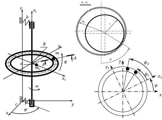
At this stage of the study it is assumed that there are no collisions between the CMs and the masses move as if in parallel planes (when moving, CMs can penetrate through each other). The system of differential equations of motion consists of six equations, and dimensionless in the matrix form are as follows:
Matrix [] presents the following expression:
where:
Matrixes and are recorded as follows:
The elements of matrix are as follows:
where , – dimensionless forces of normal pressure of CMs on the internal surface of the ABD’s body:
3. Study results of the mathematical model
A system of differential equations of motion Eq. (1) for a rotor system with an ABD with two compensating masses was investigated using SPRING software [7].
At this stage of the study, the collision between the CMs was not taken into account and it was assumed that during its motion one compensating mass does not prevent the movement of the other. We consider the influence of the rolling friction coefficient between the CMs and the internal surface of the ABD on its operation.
In this case, the initial velocity of the CM in the circumferential direction was determined and (under the initial conditions CМ: if 0 then 0, , , 0, 0, 0), which ensures its acceleration to the working speed of the rotor. When considering the acceleration of the CM, the initial conditions for the motion of the rotor are as follows: 0, 0, 0, 0, 0, 1. The study was carried out at various fixed values of the relative dissipation coefficient in the elastic suspension of the rotor: 0.145 and 0.1 and with the following parameters of the rotor system: 2,5, 15, 200, 0,5005. The mass of the CM was assumed to depend on its radius.
The results of the calculations are shown in Table 1, based on which the dependence of the initial speed of the CM and in the circumferential direction of the ABD’s body is plotted in Fig. 2, depending on the size of the dimensionless gap between the CM and the internal surface of the ABD in the cross-section. The research was carried out with the ratio of the square of the natural frequency of the elastic suspension of the rotor system to the square of the working speed of the rotor: 0,003, 0,005 and 0,01.
Fig. 2Diagram of the dependence of the initial velocity of CM v_3 and v4 in the circumferential direction of the ABD’s body on the value of the rolling friction coefficient at p= 0,005: a) n= 0,100, b) n= 0,145 1) k= 2·10-5 m; 2) k= 4·10-5 m at various values of rolling friction coefficients of relative dissipation
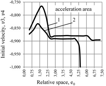
a)
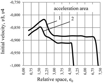
b)
Table 1Calculation results at two values of relative dissipation coefficient n in the elastic suspension of the rotor at p= 0,005
0,100 | Rolling friction coefficient 2·10-5 m | ||||||||
0,5 | 1,1 | 1,9 | 2,7 | 3,5 | 4,3 | 5,1 | 5,7 | ||
, | –0,857 | –0,804 | –0,776 | –0,881 | –0,880 | –0,878 | –0,881 | –0,880 | |
Rolling friction coefficient 4·10-5 m | |||||||||
0,5 | 1,1 | 1,9 | 2,7 | 3,5 | 4,3 | 5,1 | 5,4 | ||
, | –0,874 | –0,876 | –0,873 | –0,890 | –0,892 | –0,900 | –0,901 | –1,000 | |
0,145 | Rolling friction coefficient 2·10-5 m | ||||||||
0,5 | 1,1 | 1,9 | 2,7 | 3,5 | 4,3 | 5,1 | 5,7 | ||
, | –0,861 | –0,846 | –0,824 | –0,879 | –0,884 | –0,882 | –0,881 | –0,880 | |
Rolling friction coefficient 4·10-5 m | |||||||||
0,5 | 1,1 | 1,9 | 2,7 | 3,5 | 4,3 | 4,9 | |||
, | –0,880 | –0,862 | –0,850 | –0,891 | –0,913 | –0,912 | –1,000 | ||
Table 2The results of the calculation at two values of coefficient of relative stiffness p in the elastic suspension of the rotor at rolling friction coefficient k= 4·10-5 m at the coefficient of relative dissipation n= 0,100
0,003 | 0,5 | 1,1 | 1,7 | 2,3 | 2,9 | 3,5 | 3,9 | 4,6 | 5,0 | |
, | –0,888 | –0,868 | –0,892 | –0,929 | –0,927 | –0,912 | –0,920 | –1,000 | ||
0,010 | 0,5 | 1,1 | 1,9 | 2,7 | 3,5 | 4,3 | 5,1 | 5,4 | 5,4 | |
, | –0,388 | –0,428 | –0,565 | –0,639 | –0,701 | –0,750 | –0,868 | –0,977 | –1,000 |
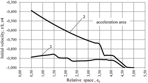
Table 2, which is the basis for diagrams in Fig. 3, shows the dependence of the initial velocity of CM and in the circumferential direction of the ABD’s body depending on the value of the dimensionless gap between the CM and the inner surface of the ADD in the cross-section at different values of dimensionless stiffness of the elastic suspension of the rotor.
Fig. 3Diagram of the dependence of the initial velocity of the CM v3 and v4 in the circumferentialdirection of the ABD’s body with rolling friction k= 4·10-5 m at the coefficient of relative dissipation n= 0,100 and at different values of the coefficients of relative stiffness 1) p= 0,003, 2) p= 0,010
4. Conclusions
The performed calculations of the mathematical model of the vertical rotor with an ABD’s body having a toroidal shape and a circular cross-section with two compensating masses concentrically fixed on it made it possible to state that the acceleration of the CM to the working speed of the rotor essentially depends on the rolling friction coefficient and the stiffness of the elastic suspension of the rotor. Reducing the stiffness of the rotor suspension allows reducing the relative gap between the body of the ABD and the CM for their acceleration to the rotor speed (to increase the size of the CM). The change in the dissipation coefficient in the rotor suspension has little effect on the conditions of CM acceleration. The results of the study do not contradict the previous results of the calculation of the ABD with one CM.
At the same time, the mathematical model of a rotor system with an ABD requires further development to take into account the collision between CMs during their acceleration to the working speed of the rotor.
References
-
Strautmanis G., Mezitis M., Strautmane V. Model of a vertical rotor with a ball-type automatic balancer. Vibroengineering Procedia, Vol. 8, 2016, p. 57-62.
-
Sperling L., Ryzhik B., Linz Ch, Duckstein H. Simulation of two-plane automatic balancing of a rigid rotor. Mathematics and Computers in Simulation, Vol. 58, Issues 4-6, 2002, p. 351-365.
-
Ryzhik B., Duckstein H., Sperling L. Partial compensation of unbalance by one- and two automatic balancing devices. International Journal of Rotating Machinery, Vol. 10, Issue 3, 2004, p. 193-201.
-
Gorbenko A. N. Influence of rotor unbalance increasing on the stability of its autobalancing. Procedia Engineering, Vol. 206, 2017, p. 266-271.
-
Goncharov V. An increase of the balancing capacity of ball or roller-type auto-balancers with reduction of time of achieving auto-balancing. Eastern-European Journal of Enterprise Technologies, Vol. 1, Issue 7, 2017, p. 15-24.
-
Strautmanis G., Jurjevs V., Cokalo V. A Balancing Device for Centrifuges of Washing Machines. LV Patents, LV 14368 B, 2011, (in Latvia).
-
Ščukins I., Zakrževskis M., Ivanov Y., et al. Application of software SPRING and method of complete bifurcation groups for the bifurcation analysis of nonlinear dynamical system. Journal of Vibroengineering, Vol. 10, Issue 4, 2008, p. 510-518.
About this article

