Abstract
This paper addresses the challenge of predictive control of a quarter-car nonlinear suspension and low controller-precision. This is done by designing and implementing an adaptive controller with time-delay compensation. First, a real-time control model is created. Then, time-delay compensation is realized and both frequency-domain and time-domain simulation of the controller performance are conducted. According to the simulation results, the sprung-mass acceleration of the suspension controlled by an adaptive controller with time-delay compensation is superior to that without time-delay compensation. Both the period to settle down and the peak of vibration acceleration are smaller. This means the proposed controller is capable of dealing with problems including variable time delay, nonlinear vibration and predictive control.
Highlights
- The structure of this algorithm can deal with nonlinear problems, so it can solve the nonlinear items of suspension system, such as nonlinear coefficient or nonlinear stiffness.
- For the full frequency band, a satisfactory control effect can be achieved as well as significantly reduced sprung-mass acceleration.
- With the proposed controller, the problem of time delay of the front suspension can be solved by a compensator.
1. Introduction
Much research has been conducted on the time-delay problem in system control processes. Examples include the semi-active control of single-DOF oscillators [1], the tracking control of reference models [2], the stability analysis of systems with time-delay effect [3], and the reduction of time-delay through improved hardware processing [4]. The time-delay of any given system consists of both variable delay and fixed delay.
For a structurally complex system, system delay is usually variable during the control process. Researchers [5] analyzed the effect of time-delay on overall stability for high-order nonlinear systems with feed-forward control. A similar case is the global output feedback control of an uncertain nonlinear system with unknown time-delay [6]. A neural network system is another complex system, and studies of its time-delay include system-state estimation that considers the effect of variable time-delay [7], stability conditions estimation [8], and its improvements [9]. Others have studied the effect of both time-delay and nonlinear perturbation on the finite-time stability of discrete systems [10] as well as the effect of variable time-delay on the master-slave synchronization conditions of Lur’e chaotic systems [11].
When the structure of a system is relatively simple, its time-delay is usually a constant value such as the time-delay of a car suspension with active control. To reduce the effect of time-delay, one research group [12] used Smith compensation. Another group [13] performed a coordinate transformation to convert a time-delay system into a time-delay-free system. Yet another group [14, 15] converted the time-delay into an error of the secondary path and reduced the effect of time-delay using error control. One study [16] conducted in-depth research of time-delay in magneto-rheological dampers. In addition, both controllers [17-19] and sliding mode controllers [20] have been used extensively with linear systems to reduce the effects of time-delay. The above studies aim to improve system-control precision by reducing the effect of time-delay. Another feasible way of achieving this aim is to use predictive control.
Two studies [21, 22] investigated predictive control to optimize linear systems. However, the results are inapplicable with respect to the control of nonlinear car-suspensions. The key for predictive control of nonlinear cars lies in the collection of road information using the front tires, which enables predictive control of the rear tires [23-28]. In this case, there is no predictive control of the front suspension, so the control effect of the entire car is affected. The above studies helped to eliminate the effect of time-delay but there is room for improvement.
Furthermore, the above studies indicate that a high-precision controller like the controller is effective in a linear system but tends to be less effectivein a nonlinear system. With a variable time-delay in a nonlinear system, the controllers without a predictator reported so far are inadequate in decreasing the vibration of car body. The predictive control cannot solve time delay problem of the front suspension. In other words, the time-delay is not completely solved. Inspired by researches done by Wu Deng, et al. [29, 30], this paper introduces an adaptive controller with the aim to improve the active control of quarter-car nonlinear suspensions, while considering the time-delay effect. The proposed method addresses the problems of the inefficient of a controller used in a nonlinear system, the inadequate of a controller used to eliminate the variable time delay and the low precision of a controller used in front suspension.
This paper is organized as follows: Chapter 2 describes a control model for quarter-car nonlinear active suspensions and an adaptive controller with time-delay compensation. Chapter 3 focuses on the simulation of the designed controller. This is followed by an experimental verification in Chapter 4, while Chapter 5 summarizes the conclusions of this paper.
2. Mathematical model for quarter-car nonlinear active suspensions
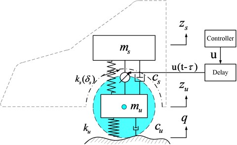
Shown in Fig. 1 is the quarter-car suspension model, where body mass and passenger mass are modeled as a single sprung mass (which varies with the load within a small range, and it has both upper and lower limits). Tire mass, brake system, and other link masses are modeled as unsprung mass . Sprung mass and unsprung mass are connected via a spring and damper . The spring is modeled as linear spring and nonlinear spring . The unsprung mass is supported by the ground via an equivalent linear spring and linear damper . For the active suspension, the actuator generates an active control force to improve comfort. represents the unevenness of the road.
Fig. 1Nonlinear quarter-car suspension with active controller
According to Newton’s second law, the dynamic equation of the quarter-car suspension model is:
where:
After defining the state variables , , and , Eq. (1) can be rewritten as:
where, . is a parameter that varies with load and meets the condition:
Car suspension control is a multi-objective control problem, through which we can not only improve ride comfort but also guarantee a safe performance and to stay within the suspension limits. These conditions can be expressed as:
where, represents the maximum working space of the suspension; represents a finite period of time.
The tracking error is defined as ; represents a reference signal thatis continuous and differentiable, and . Its differential form is:
is selected as the virtual control input of the above formula, and its ideal function is . At the same time, a time-delay is unavoidable in a realistic control system, so the control effect of the controlled suspension is affected. At this point, a compensation is needed. The error is defined as:
After substituting Eq. (6) into Eq. (5), we obtain:
After taking the derivative of Eq. (6), we can write:
We then select the following ideal function:
where, represents a positive constant.
We define:
where, represents the estimate of .
We define the adaptive rate as:
where, is a positive constant.
And set the active control force as:
We then consider the Lyapunov candidate function:
For any 0, a set is always a compact set:
In a compact set , has a maximum value, and, given that is continuous, also has a maximum value. In addition, considering the perfect nature of the square, we can write:
After taking the derivative of and substituting it into Eqs. (6)-(9), (11) and (12), we obtain:
where, . As can be seen from Eq. (16), if:
We can formulate:
to obtain:
According to Eq. (19), when , , , has a boundary.
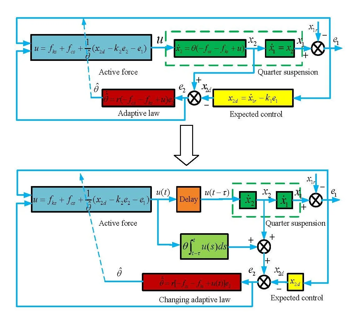
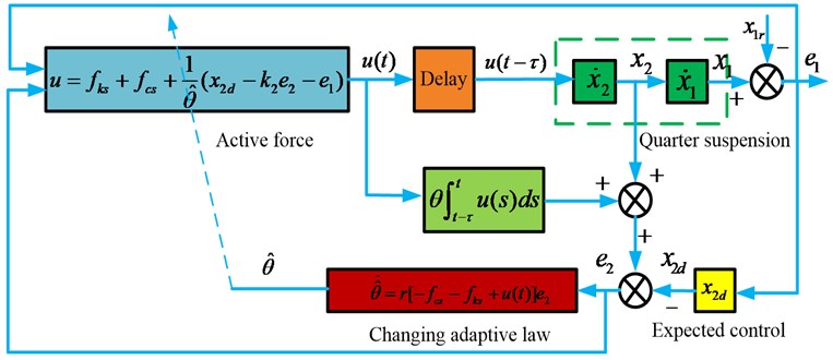
A schematic of the controller with time-delay compensation is shown in Fig. 2.
Fig. 2Adaptive controller with time-delay compensation
3. Numerical simulation
The parameters for the quarter-car suspension model are shown in Table 1.
The controller parameters are shown in Table 2.
Table 1Parameters used in the quarter-car suspension model
Parameter | |||||||
Unit | kg | kg | N/m | N/m | N/m | Ns/m | Ns/m |
Numerical value | 324 | 45 | 20,000 | 2,000 | 180,000 | 1,000 | 500 |
Table 2Controller parameters
Parameter | |||||
Numerical value | 0.01 | 10 | 10 | 1/350 | 1/300 |
A simulation analysis was conducted for the following scenarios:
(a) Adaptive control with time-delay compensation ( 0.01 s),
(b) Adaptive control without time-delay compensation ( 0.01 s),
(c) Passive state.
3.1. Frequency domain analysis
As shown in Fig. 3(a), the new controller can ensure a satisfactory ride comfort. In addition, for the full frequency range and despite delays in the control system, the sprung mass acceleration in the controlled state remains below that of the passive state. This meets the requirements for high-precision system control.
As shown in Fig. 3(b) and Fig. 3(c), within the low-frequency range (< 20 rad/s), both the dynamic movement of the suspension and the dynamic load of the tire with adaptive control are reduced.
Fig. 3Frequency response of: a) sprung mass acceleration, b) suspension space, c) dynamic load of tire
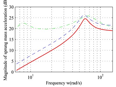
a)
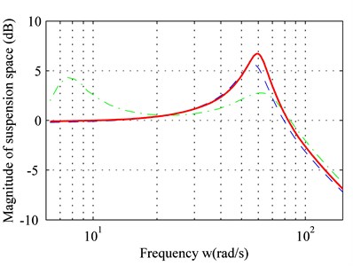
b)
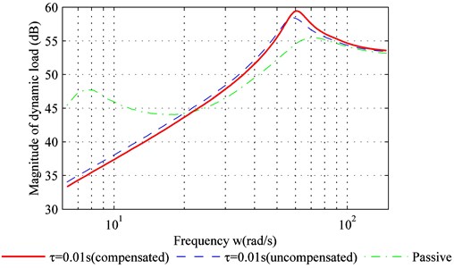
c)
For the medium-frequency range (20 rad/s-80 rad/s) both dynamic movement of the suspension and the dynamic load of the tire have increased due to the adaptive control. They exceed that of the passive suspension, and a peak value is produced within the frequency band.
For the high-frequency range (> 80 rad/s), the dynamic movement of the suspension and the dynamic load of the tire with adaptive controller are similar to the passive suspension. In addition, Fig. 3 suggests that time-delay compensation can increase the controller effect and reduce sprung-mass acceleration.
3.2. Time domain analysis
A simulation was performed fortwo road types: bump road and C level road. The simulation for the bump road was conducted using the following function:
The C-level road is the most common road type for cars, and its frequency band covers the points of resonance for both sprung mass and unsprung mass.
Fig. 4 shows the suspension response for two road types. According to Eq. (20), the duration from zero to peak value point of the bump road is 0.125 s, and the delay-time of the controller is 0.01 s. In other words, the suspension was set to a controlled state 0.01 s after excitation, and a delay of 0.01 s is maintained afterwards. Therefore, given that the delay is less than 0.125 s, the suspension is already in the controlled state before it reaches the peak value for the bump road. However, if the delay-time exceeds 0.125 s, the maximum sprung-mass acceleration of the controlled suspension is equal to that of the passive suspension. In other words, controller delay should be minimized.
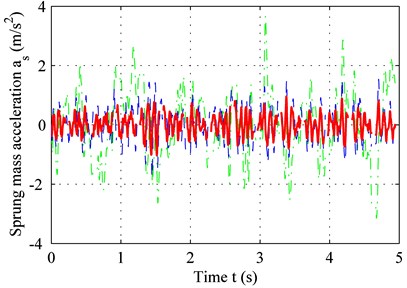
As seen in Fig. 4(a) and 4(c), the adaptive controller with time-delay compensation performs better thanks to a smaller error and reduced sprung-mass acceleration for bump road. The same result can be obtained in C level road from Fig. 4(b) and 4(d).
Fig. 4Sprung-mass acceleration of: a) bump road, b) C-level road; tracking error of, c) bump road, d) C-level road
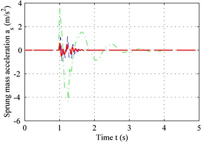
a)
b)
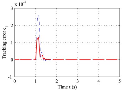
c)
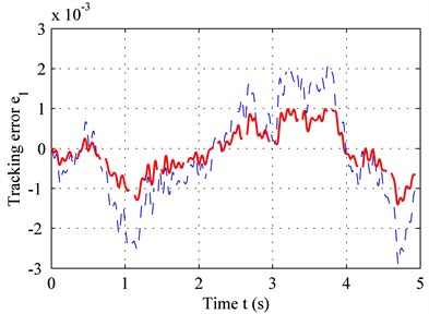
d)
As shown in Fig. 5, due to the time-delay, the adaptive controller without time-delay compensation may even deteriorate ride comfort and increase sprung-mass acceleration near the point of resonance (60 rad/s). The adaptive controller with time-delay compensation, on the other hand, can reduce sprung-mass acceleration. For a realistic random road type, the higher the frequency, the lower is the power spectrum, and the lower the frequency, the higher is the power spectrum. For large-amplitude vibrations, the sprung-mass acceleration of the controlled suspension is lower because of the low frequency – see Fig. 4(b). For small-amplitude vibrations, the sprung-mass acceleration of the controlled suspension shows no significant decline because of the high frequency – see Fig. 5. Overall, time-delay is unavoidable and may even reduce sprung-mass acceleration for high frequencies. However, the controller with time-delay compensation can reduce the effect of time-delay and improve ride comfort.
An overview of the RMS values for sprung-mass acceleration for the two road types is shown in Table 3.
According to Table 3, the controller with time-delay compensation performs better than the controller without time-delay compensation. Compared to the passive suspension, the sprung-mass acceleration declined by 89.15 % (with time-delay compensation), by 78.55 % (without time-delay compensation) for the bump road, and by 69.06 % (with time-delay compensation), and 54.04 % (without time-delay compensation) for the C-level road.
Fig. 5PSD of sprung-mass acceleration in frequency domain
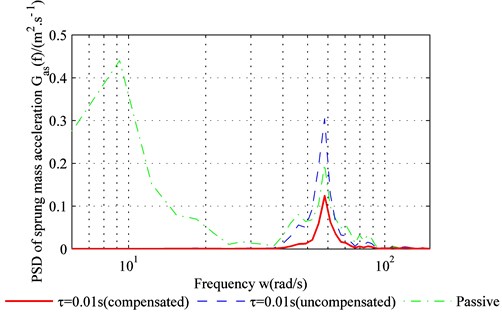
Table 3RMS values for sprung-mass acceleration
Road type | Bump road | C level road |
Passive (m/s2) | 0.7868 | 1.1139 |
Adaptive active (with time-delay compensation) (m/s2) | 0.0854 | 0.3446 |
Adaptive active (without time-delay compensation) (m/s2) | 0.1688 | 0.512 |
4. Experimental verification
To better understand the effectiveness of the controller with time-delay compensation, a bench test was carried out – see Fig. 6. The actuator used in the test consists of a rack and a pinion.
Fig. 6Experimental setup for the bench test
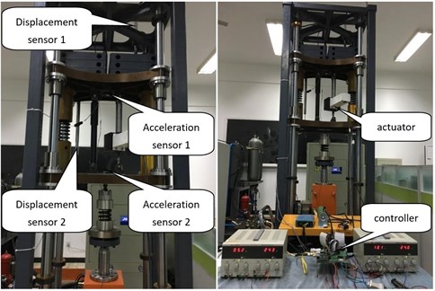
The base excitation is provided by a hydraulic cylinder. A spring, which functions as a tire, is placed between the hydraulic cylinder and the unsprung mass. The sprung mass and the unsprung mass are connected via a damper and an actuator. The parameters of the system are shown in Table 1. The controller proposed in this work runs on an embedded system.
Because four different sensors were installed for the test, we can measure the sprung-mass displacement, the sprung-mass acceleration, the unsprung-mass acceleration, and the relative displacement between sprung mass and unsprung mass, respectively. After differentiating the displacement, we can derive the velocity. These signals are used as inputs of the control system. The actuator represents the output of the system.
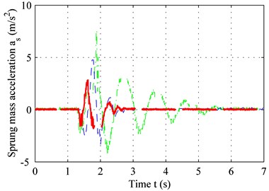
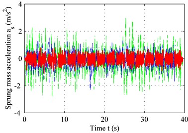
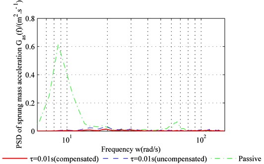
Fig. 7 shows the sprung mass acceleration results for both the bump road and the C level road. The delay-time 0.01 s and other parameters are identical to those shown in Table 1 and Table 2. According to Fig. 7(a) and Fig. 7(b), the performance of the adaptive controller with time-delay compensation is clearly superior to that of the adaptive controller without time-delay compensation. Both the period to settle down and the peak of vibration acceleration are the least for controller with compensation, shown in Fig. 7(a). The performance remains the same in regardless of the road type. This can be concluded from the result depicted in Fig. 7(b), in which the average acceleration under the controller with compensation is the smallest. The power spectrum chart in Fig. 7(c) confirms this result. Both the time domain result and the frequency domain result demonstrate that the proposed method can solve the problems mentioned above.
Fig. 7Sprung-mass acceleration for: a) bump road, b) C level road, c) PSD of sprung mass acceleration
a)
b)
c)
5. Conclusions
It is challenging to realize effective predictive control for a quarter-car nonlinear suspension system. One approach this challenge is to transform the problem into a problem of control with time-delay. This paper proposes an adaptive controller with improved precision for nonlinear systems and time-delay compensation. The results are compared with a controller without time-delay compensation:
1) With the proposed controller, the problem of time delay of the front suspension can be solved. This is done by a compensator. Unlike the linear algorithm, this algorithm does not need to establish the state equation of the linear system. The structure of this algorithm can deal with nonlinear problems, so it can solve the nonlinear items of suspension system, such as nonlinear coefficient or nonlinear stiffness.
2) Using the controller designed in this study, both dynamic travel and dynamic load of the tire with the suspension increased within the medium-frequency band. However, for the full frequency band, a satisfactory control effect can be achieved as well as significantly reduced sprung-mass acceleration. The bench test results are consistent with the results of the theoretical analysis, which confirms the improved effectiveness of the new controller.
References
-
Shen Y. J., Yang S. P., Xing H. J., Pan C. Z. Analytical research on a single degree-of-freedom semi-active oscillator with time delay. Journal of Vibration and Control, Vol. 19, Issue 12, 2012, p. 1895-1905.
-
Wang D., Wu S., Zhang W., Wang G., Wu F., Okubo S. Model following control system with time delay. Kybernetika, Vol. 52, Issue 3, 2016, p. 478-495.
-
Jin Y., Chang P. H., Jin M., Gweon D. G. Stability guaranteed time-delay control of manipulators using nonlinear damping and terminal sliding mode. IEEE Transactions on Industrial Electronics, Vol. 60, Issue 8, 2013, p. 3304-3317.
-
Shoukry Y., El Kharashi M.-W., Hammad S. An embedded implementation of the generalized predictive control algorithm applied to automotive active suspension systems. Computers and Electrical Engineering, Vol. 39, 2013, p. 512-529.
-
Zhao C. R., Xie X. J. Global stabilization of stochastic high-order feedforward nonlinear systems with time-varying delay. Automatic, Vol. 50, Issue 1, 2014, p. 203-210.
-
Yu W., Liu S., Zhang F. Global output feedback regulation of uncertain nonlinear systems with unknown time delay. International Journal of Control, Automation and Systems, Vol. 13, Issue 2, 2015, p. 327-335.
-
Ren J., Zhu H., Zhong S., Ding Y., Shi K. State estimation for neural networks with multiple time delays. Neurocomputing, Vol. 151, 2015, p. 201-210.
-
Shi K., Zhong S., Zhu H., Liu X., Zeng Y. New delay-dependent stability criteria for neutral-type neural networks with mixed random time-varying delays. Neurocomputing, Vol. 168, 2015, p. 896-907.
-
Shi K., Zhu H., Zhong S., Zeng Y., Zhang Y. Improved delay-dependent stability criteria for neural networks with discrete and distributed time-varying delays using a delay-partitioning approach. Nonlinear Dynamics, Vol. 79, 2015, p. 575-592.
-
Kang W., Zhong S., Shi K. Finite-time stability for discrete-time system with time-varying delay and nonlinear perturbations. ISA Transactions, Vol. 60, 2016, p. 67-73.
-
Yao J., Zhang J., Zhao M., Peng H. Analysis of dynamic stability of nonlinear suspension concerning slowly varying sprung mass. Shock and Vibration, Vol. 2017, 2017, p. 5341929.
-
Shi K., Liu X., Zhu H., Zhong S., Zeng Y., Yin C. Novel delay-dependent master-slave synchronization criteria of chaotic Lur’s systems with time-varying-delay feedback control. Applied Mathematics and Computation, Vol. 282, 2016, p. 137-154.
-
Pang H., Fu W. Q., Liu K. Stability analysis and fuzzy smith compensation control for semi-active suspension systems with time delay. Journal of Intelligent and Fuzzy Systems, Vol. 29, 2015, p. 2513-2525.
-
Alves U. N. L. T., Garcia J. P. F., Teixeira M. C. M., Garcia C. S., Rodrigues F. B. Sliding mode control for active suspension system with data acquisition delay. Mathematical Problems in Engineering, Vol. 2014, 2014, p. 529293.
-
Yuxue P., Fang Z., Jinhui J. A new online secondary path modeling method for adaptive active structure vibratino control. Smart Materials and Structures, Vol. 23, Issue 6, 2014, p. 065015.
-
Chen Z., Huang S., Yu D. Mechanical-delay dynamic model of magnetoriological damper. Journal of Donghua University, Vol. 31, Issue 4, 2014, p. 401-405.
-
Sakthivel R., Arunkumar A., Mathiyalagan K., Selvi S. Robust reliable control for uncertain vehicle suspension systems with input delays. Journal of Dynamic Systems, Measurement, and Control, Vol. 137, 2015, p. 041013.
-
Li H., Jing X., Karimi H. R. Output-feedback-based H∞ control for vehicle suspension systems with control delay. IEEE Transactions on Industrial Electronics, Vol. 61, Issue 1, 2014, p. 436-446.
-
Kong Y., Zhao D., Yang B., Han C., Han K. Robust non-fragile H/L2-L control of uncertain linear system with time-delay and application to vehicle active suspension. International Journal of Robust and Nonlinear Control, Vol. 25, 2015, p. 2122-2141.
-
Gupta S., Ginoya D., Shendge P. D., Phadke S. B. An inertial delay observer-based sliding mode control for active suspension systems. Journal of Automobile Engineering, Vol. 230, Issue 3, 2016, p. 352-370.
-
Wu J., Liao F., Tomizuka M. Optimal preview control for a linear continous-time stochastic control system in finite-time horizon. International Journal of Systems Science, Vol. 48, Issue 1, 2017, p. 129-137.
-
Wu J., Liao F., Tang Y. Y. Applications of the preview control method to the optimal problem for linear continuous-time stochastics systems with time-delay. International Journal of Wavelets, Multiresolution and Information Processing, Vol. 14, Issue 6, 2016, p. 1650045.
-
Kong Y., Zhao D., et al. Non-fragile multiobjective static output feedback control of vehicle active suspension with time-delay. International Journal of Vehicle Mechanics and Mobility, Vol. 52, Issue 7, 2014, p. 909942.
-
Li P., Lam J., Cheung K. C. Velocity-dependent multi-objective control of vehicle suspension with preview measurements. Mechatronics, Vol. 24, 2014, p. 464-475.
-
Xie Z., Wong P. K., Zhao J., Xu T., Wong K. I., Wong H. C. A noise-insensitive semi-active air suspension for heavy-duty vehicles with an integrated fuzzy-wheelbase preview control. Mathematical Problems in Engineering, Vol. 2013, 2013, p. 121953.
-
Göhrle C., Schindler A., Wagner A., Sawodny O. Design and vehicle implementation of preview active suspension controllers. IEEE Transactions on Control Systems Technology, Vol. 22, Issue 3, 2014, p. 1135-1142.
-
Youn, Tchamna R., Lee S. H., Uddin N., Lyu S. K., Tomizuka M. Preview suspension control for a full tracked vehicle. International Journal of Automotive Technology, Vol. 15, Issue 3, 2014, p. 399-410.
-
Li P., Lam J., Cheung K. C. Multi-objective control for active vehicle suspension with wheelbase preview. Journal of Sound and Vibration, Vol. 333, 2014, p. 5269-5282.
-
Deng W., Zhao H., Yang X., Xiong J., Sun M., Li B. Study on an improved adaptive PSO algorithm for solving multi-objective gate assignment. Soft Computing, Vol. 59, 2017, p. 288-302.
-
Deng W., Zhao H., Liu J., Xiaolinyan, Li Y., Yin L., Ding C. An improved CACO algorithm based on adaptive method and multi-variant strategies. Soft Computing, Vol. 19, Issue 3, 2015, p. 701-713.
Cited by
About this article

