Abstract
The robotic arm carrying a moving end effector can be modeled as a rotating beam with moving mass. Active vibration control of rotating beam with moving mass using piezoelectric actuator is presented. Simply supported beam and cantilevered beam are considered in this studying. The equations of the system are derived by Lagrange’s equation with the assumed mode method. The linear classical optimal control algorithm with displacement-velocity feedback is used to determine the control voltage. The numerical simulations reveal that the transverse displacements of the beam can be effectively reduced by the actuators. The effect of rotational speed and acceleration to the dynamic responses of the beam are also investigated.
Highlights
- The vibration control of rotating beam with moving mass is studied.
- Using piezoelectric materials as the actuator.
- The equations of the system are derived by Lagrange’s equation.
- The displacement-velocity feedback is used to determine the control voltage.
- The simulation results show that the vibration of the structure is effectively suppressed.
1. Introduction
Piezoelectric materials have been more and more often applied to improve structural behavior. Such materials can actuate forces by electrical excitation, making them suitable as actuators for vibration control. Besides, they can sense deformation and generate a real-time voltage signal. Therefore, they can be used as sensor as well. Many researchers applied the piezoelectric actuator/sensor pairs to control the vibration of structures [1-6]. While other researchers used the piezoelectric actuators only to suppress the dynamic vibration of structures [7-12]. And some control algorithm is used to determine the control voltage.
The problem of the structures under the influence of moving loads or moving mass are of technological importance and has attracted the attention of many researchers in the last few decades. There are a lot of works can be found in the published literature [9-19]. And we can find some studies in the literature about active vibration control of dynamic response of such structures using piezoelectric actuator. Sung [9] and Nikkhoo et al. [10] studied the active control of a simply supported Euler-Bernoulli beam under a moving mass using piezoelectric actuator, respectively. And latter, Nikkhoo et al. [11] investigated the vibration control of a single span Euler-Bernoulli beam with geometrically nonlinear behavior under an arbitrary dynamic loading. Rofooei and Nikkhoo [12] investigated a thin rectangular plate with a number of piezoelectric patches bonded on its surface under the excitation of a moving mass. The moving mass is assumed to travel along linear and orbiting path over the plate respectively. In these studies, a linear classical optimal control algorithm with displacement-velocity feedback is used to determine the control voltage.
The problem becomes more difficult if the beam rotates around one end of it. For example, the robotic arm carrying a moving end effector rotates in the vertical plane. For a rotating beam with moving mass, the interaction between rigid and flexible body motions is highly demanded. To the author’s knowledge, active vibration control of beam with a moving mass that rotates in the vertical plane using piezoelectric actuator has not been reported. The author of this paper has studied this problem. Simply supported beam as well as cantilevered beam are considered. Lagrange’s equation with the assumed mode method is employed to derive the equations of motion. The linear classical optimal control algorithm with displacement-velocity feedback is used to determine the control voltage. Finally, a number of examples are presented to evaluate the control effect.
2. Formulation of the equations of motion
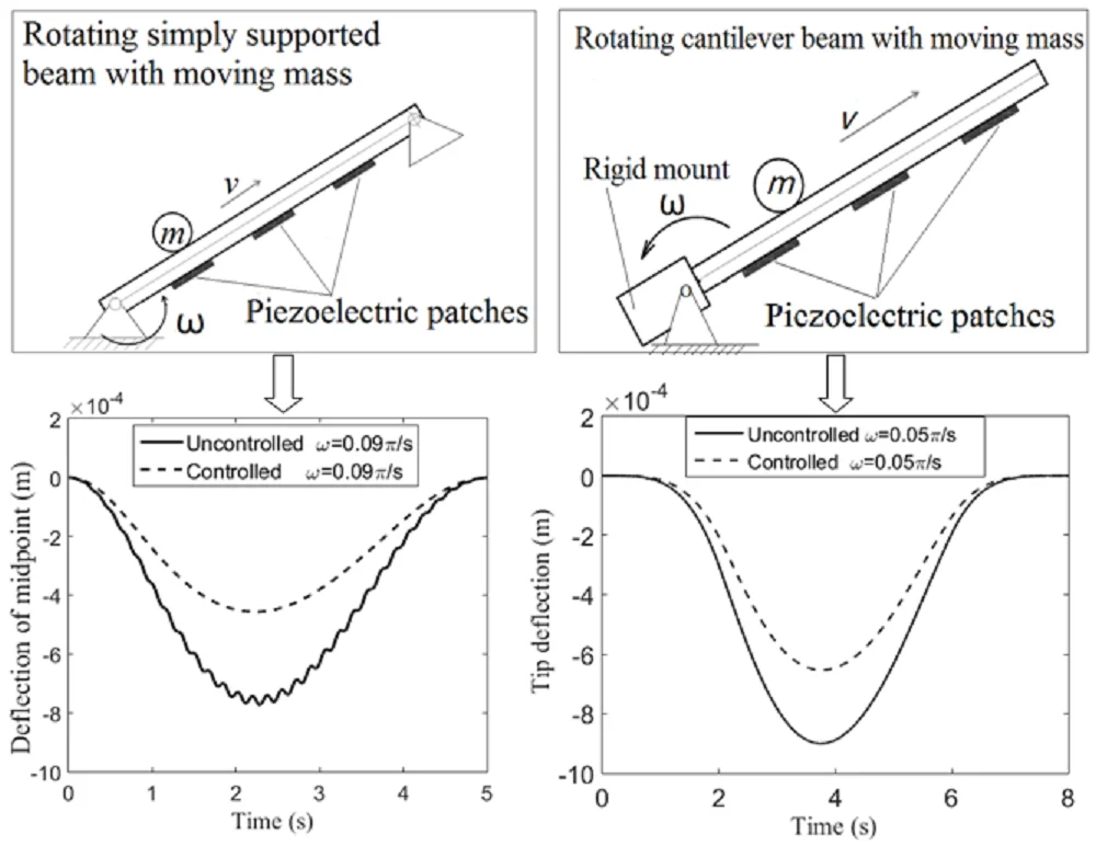
A uniform simply supported beam with moving mass is displayed in Fig. 1. One support base of the beam is fixed, and the other one can rotates around the fixed one. is the global reference frame, while is the rotating reference frame. Angle between the rotating reference frame and the global reference frame is denoted as . In this studying, 0 ≤ < /2 is considered.
Fig. 1A rotating simply supported beam with moving mass
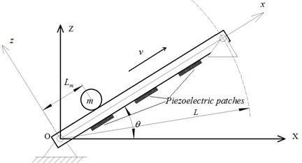
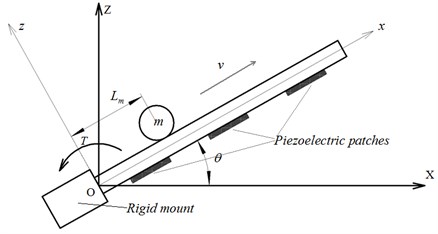
The moving mass moves along the beam. and are the mass and traveling speed of the moving mass respectively. is the displacement of the moving mass in the direction. The moving mass experiences a combination of rotational and linear motion. The transverse and axial vibration deformation of the beam in the reference frame is denoted as and respectively. There are piezoelectric patches as the actuators are bonded on the bottom surface of the beam and positioned by the coordinates and + 1, 2, …, in the reference frame . is the length of the piezoelectric patches. and are the thicknesses of the beam and piezoelectric patches, respectively. The width of the beam and the piezoelectric patches are both . Fig. 2 shows a cantilevered beam with moving mass. One end of the beam is fixed to a rigid mount and the other end is free. Torque rotates the rigid mount about axis.
Fig. 2A rotating cantilever beam with moving mass
Euler-Bernoulli beam theory is employed to analyze the beam. The normal stress and strain of the beam in the axial direction are expressed as:
where is the elastic modulus, and are the axial and vertical displacements, respectively. Let the piezoelectric patches be polarized along the direction. The axial stress, strain and the electrical displacement of the piezoelectric patches can be expressed as:
where is the elastic stiffness, is the electrical displacement, is the electrical field in the direction [6] and is the external applied voltage. is the dielectric constant, and is the piezoelectric constant.
The global position of an arbitrary material point p on the beam can be expressed as:
where is the rotational transformation matrix from the moving coordinate system to the fixed reference frame and is the location of the point in the rotating coordinate system , they can be written as:
The velocity of an arbitrary material point is:
where is the angular velocity of the beam, and:
Substituting Eq. (4) and Eq. (6) into Eq. (5), we will arrive at:
The kinetic energy of the beam can be written as:
where and are the mass density, and and are the cross-sectional area of the beam and the piezoelectric patches respectively. and are the rotational inertia of the beam and the piezoelectric patches respectively. By substituting for the value of from Eq. (7) and making use of some trigonometric properties, the kinetic energy of the beam can be expressed as:
where:
The strain energy of the beam, and the strain energy and electric potential energy of the piezoelectric patches can be written as:
Substituting Eq. (1) and Eq. (2) into Eq. (11), we can obtain:
where:
and is the control voltage of the th piezoelectric patch. The gravitational potential energy of the beam can be written as:
Now, let us consider the kinetic energy and potential energy of the moving mass. For a concentrated moving mass, the kinetic energy is:
where:
and:
Substituting Eq. (15) into Eq. (14), we will get:
The gravitational potential energy of the concentrated moving mass can be written as:
The total kinetic energy and potential energy of the system can be expressed as:
Lagrange’s equation with the assumed mode method is used to determine the equation of motion of the structural system. To use the assumed mode method, the flexible displacements of the beam can be expressed in terms of the generalized coordinates and displacement shape functions:
where , , and . For simply supported beam, the shape functions can be written as:
while for cantilevered beam, the shape functions are:
where is obtained from the following characteristic equation:
Lagrange’s equation is written as:
Substituting the energy expressions into Eq. (25), the equation of motion of the whole structural system is gotten:
where:
The expressions of these matrices are listed in the Appendix. Eq. (26) characterizes the piezoelectric actuators driven under the external applied voltages. The state-space formulation of Eq. (26) is given as:
where:
3. Active vibration control
A linear classical optimal control algorithm with displacement-velocity feedback is used to determine the control voltage. The cost function to be minimized is given by:
where:
is the output equation and is the output matrix. and are the semi-positive-definite and positive-definite weighting matrices on the outputs and control inputs respectively. Assuming full state feedback, the control law is given by:
where is the control gain given by:
satisfies the Riccati equation [12]:
Substituting Eq. (30) into Eq. (27) leads to:
The controlled response of the system can be gotten by solving Eq. (33).
4. Numerical simulation
In this section, several numerical examples are presented to evaluate the active control of rotating beam with moving mass. The material of the beam is steel, which 209 GPa, 7800 kg/m3. The piezoelectric material is PZT-5H, which 49 GPa, 7500 kg/m3, –6.5 C/ m2, and 1.3×10⁻⁸ F/m.
First, the concentrated mass travelling on the rotating simply supported beam is considered. The dimensions of the system are 2 m, 0.1 m, 0.03 m, 0.01 m, 0.005 m. The moving mass is 0.4 kg. Six piezoelectric patches have been considered to be attached on the bottom surface of the beam. Their locations are 0.4 m, 0.6 m, 0.85 m, 1.05 m, 1.3 m, 1.5 m. The initial conditions are: 0, 0. The rotational speed of the beam is 0.09 rad/s, and the travelling speed of the moving mass is 0.4 m/s. The matrix and are given as follows:
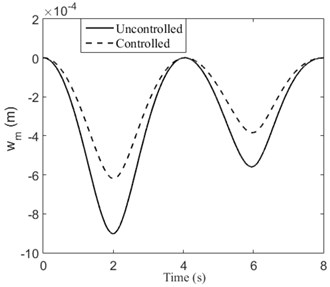
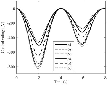
where , , and is diagonal matrix. Fig. 3 shows the transverse displacement of midpoint () of the rotating simply supported beam. For comparison, the responses when the beam does not rotate ( 0) are also given. It can be observed from Fig. 3 that the transverse displacements of the beam are reduced significantly by the actuators. When the beam rotates, the transverse component of gravity of the moving mass decreases. Thereby, it can be seen clearly from Fig. 3 that the deflection of the beam is smaller when it rotates than it does not. The required control voltages for the piezoelectric patches (p1-p6) under different rotational speed are shown in Fig. 4. We can find that larger rotational speed results in smaller control voltage.
Fig. 3Transverse displacements of the rotating simply supported beam
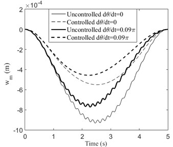
Fig. 4Control voltage of each piezoelectric patch for the rotating simply supported beam
a)
b)
The moving mass moves with variable speed is also considered. The movement rule of the system is given as follows:
At the beginning, 0, 0, 0;
When 0 2, , 0.5m/s2, 0.05 rad/s;
When 2 4, , –0.5 m/s2, 0.05 rad/s;
When 4 6, , –0.5 m/s2, 0.05 rad/s;
When 6 8, , 0.5 m/s2, 0.05 rad/s.
The numerical simulation results are given in Fig. 5. As we expected, the vibration of the beam is suppressed.
Fig. 5When the moving mass moves with variable speed: a) transverse displacement of midpoint of beam, b) control voltage, c) trajectory of the moving mass
a)
b)
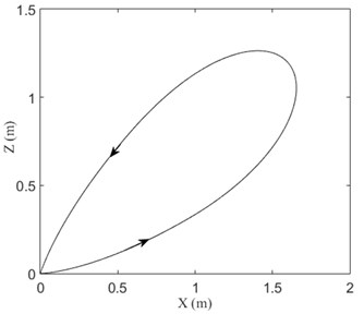
c)
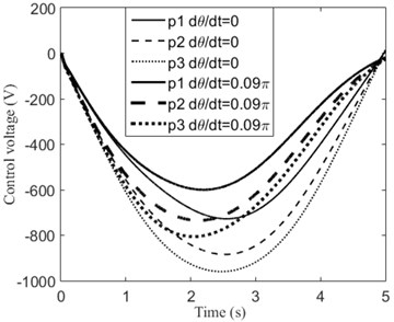
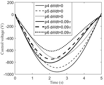
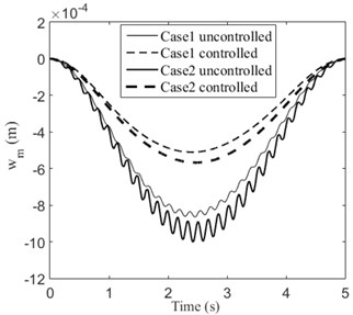
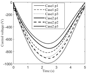
In order to investigate the effect of angular acceleration to the system, two cases are considered: Case 1, 0.4 m/s, 0.05 rad/s, 0; Case 2, 0, 0.02 rad/s2. The initial conditions are: 0, 0. At the end of time (5 s), the beam has the same angular displacement (0.25) in the two cases. The simulation results are displayed in Fig. 6. It is observed that the beam has larger transverse displacement in Case 2. This is caused by inertial force due to angular acceleration. Obviously, the transverse displacements of the beam are significantly reduced in both cases. The required control voltages for the piezoelectric patches of the two cases are displayed in Fig. 7. We can see that larger control voltages are required in Case 2.
Finally, the concentrated mass travelling on the rotating cantilevered beam is investigated. The length of the beam is 1 m. Other dimensions of the system are the same as the rotating simply supported beam. Three piezoelectric patches are used in this studying and their locations are 0, 0.2 m, 0.4 m. The movement rule of the system is given as follows:
At the beginning, 0, 0, 0;
When 0 2, , 0.25 m/s2, 0.05 rad/s;
When 2 4, , –0.25 m/s2, 0.05 rad/s;
When 4 6, , –0.25 m/s2, 0.05 rad/s;
When 6 8, , 0.25 m/s2, 0.05 rad/s.
Fig. 6Transverse displacements of Case 1 and Case 2
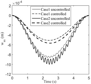
Fig. 7Control voltage of each piezoelectric patch of Case 1 and Case 2
a)
b)
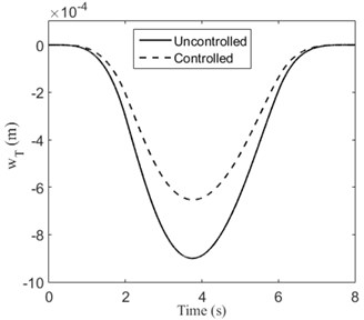
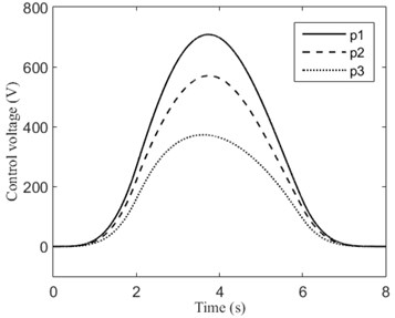
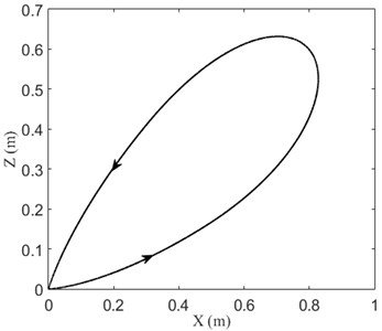
The matrix and are the same as in the previous examples. We can observe from Fig. 8 that the transverse displacements are reduced significantly, where denotes the tip deflection of the beam. The trajectory of the moving mass is shown in Fig. 9.
Fig. 8Tip displacements and control voltages of the rotating cantilevered beam
a)
b)
Fig. 9Trajectory of the moving mass when v= 0.2 m/s, θ˙= 0.05π rad/s
5. Conclusions
In present paper, active vibration control of rotating beam with moving mass using piezoelectric actuator is investigated. Rotating simply supported beam and cantilevered beam are considered in our studying. The equations of the system are derived by Lagrange’s equation with the assumed mode method. The linear classical optimal control algorithm with displacement-velocity feedback is used to determine the control voltage.
Some numerical examples are employed to evaluate the control performances. It is found that the vibration of the beam can be effectively reduced by the actuators both for rotating simply supported beam and cantilevered beam. Moreover, larger rotational speed results in smaller deflection and control voltage. When there is a uniform angular acceleration, larger vibration amplitudes are gotten. This is caused by inertial force due to angular acceleration.
References
-
Sun B., Huang D. Vibration suppression of laminated composite beams with a piezoelectric damping layer. Composite Structures, Vol. 53, Issue 4, 2001, p. 437-447.
-
Chen L. W., Lin C. Y., Wang C. C. Dynamic stability analysis and control of a composite beam with piezoelectric layers. Composite Structures, Vol. 56, Issue 1, 2002, p. 97-109.
-
Lin J. C., Nien M. H. Adaptive control of a composite cantilever beam with piezoelectric damping-modal actuators/sensors. Composite Structures, Vol. 70, Issue 2, 2005, p. 170-176.
-
Qiu Z. C., Zhang X. M., Wu H. X., Zhang H. H. Optimal placement and active vibration control for piezoelectric smart flexible cantilever plate. Journal of Sound and Vibration, Vol. 301, Issues 3-5, 2007, p. 521-543.
-
Kumar K. R., Narayanan S. Active vibration control of beams with optimal placement of piezoelectric sensor/actuator pairs. Smart Materials and Structures, Vol. 17, Issue 5, 2008, p. 055008.
-
Song Z. G., Li F. M. Active aeroelastic flutter analysis and vibration control of supersonic beams using the piezoelectric actuator/sensor pairs. Smart Materials and Structures, Vol. 20, 2011, p. 055013.
-
Raja S., Prathap G., Sinha, P. K. Active vibration control of composite sandwich beams with piezoelectric extension-bending and shear actuators. Smart Materials and Structures, Vol. 11, Issue 1, 2002, p. 63-71.
-
Hu Y. R., Ng A. Active robust vibration control of flexible structures. Journal of Sound and Vibration, Vol. 288, Issues 1-2, 2005, p. 43-56.
-
Sung Y. G. Modelling and control with Piezo-Actuators for a simply supported beam under a moving mass. Journal of Sound and vibration, Vol. 250, Issue 4, 2002, p. 617-626.
-
Nikkhoo A., Rofooeia F. R., Shadnam M. R. Dynamic behavior and modal control of beams under moving mass. Journal of Sound and Vibration, Vol. 306, Issues 3-5, 2007, p. 712-724.
-
Nikkhoo A., Amankhani M., Ghafari H. Vibration suppression in smart thin beams with piezoelectric actuators under a moving load/mass accounting for large deflections of the base structure. Indian Journal of Science and Technology, Vol. 7, Issue 2, 2014, p. 211-220.
-
Rofooei F. R., Nikkhoo A. Application of active piezoelectric patches in controlling the dynamic response of a thin rectangular plate under a moving mass. International Journal of Solids and Structures, Vol. 46, Issues 11-12, 2009, p. 2429-2443.
-
Lin Y. H., Trethewey W. M. Active vibration suppresion of beam structures subjected to moving loads: A feasibility study using finite elements. Journal of Sound and Vibration, Vol. 166, Issue 3, 1993, p. 383-395.
-
Ryu B. J., Kong Y. S. Dynamic Responses and Active Vibration Control of Beam Structures under a Travelling Mass. Intech Publisher, 2012.
-
Esmailzadeh E., Ghorashi M. Vibration analysis of beams traversed by uniform partially distributed moving masses. Journal of Sound and Vibration, Vol. 184, Issue 1, 1995, p. 9-17.
-
Michaltsos G., Sophianopoulos D., Kounadis A. N. The effect of a moving mass and other parameters on the dynamic response of a simply supported beam. Journal of Sound and Vibration, Vol. 191, Issue 3, 1996, p. 357-362.
-
Esmailzadeh E., Ghorashi M. Vibration analysis of a Timoshenko beam subjected to a travelling mass. Journal of Sound and Vibration, Vol. 199, Issue 4, 1997, p. 615-628.
-
Mofid M., Shadnam M. On the response of beams with internal hinges, under moving mass. Advances in Engineering Software, Vol. 31, Issue 5, 2000, p. 323-328.
-
Wu J. J. Dynamic analysis of an inclined beam due to moving loads. Journal of Sound and Vibration, Vol. 288, Issues 1-2, 2005, p. 107-131.
About this article

This work was funded by the Shanghai Education Commission Project for Academic Degree Construction and Research on Industrial Robot Applications under Project No. 230001-17-13.
