Abstract
The working environment of mine dump truck is relatively harsh, thus the suspension system with poor performance will directly affect driver's driving comfort and physical and mental health. An oil cylinder is one of the key components of the hydro-pneumatic suspension system, however, the high friction levels between cylinder and piston would lead to ‘friction locking’ phenomenon in the practical application. In order to improve the vibration damping performance of hydro-pneumatic suspension system and enhance the comfortability of whole vehicle, a 110 t mine dump truck was studied by theoretical and experimental method. The results of this study show that increasing the length of cylinder guide can effectively decrease the cylinder vibration transmission rate and improve the driving comfortability of vehicle.
1. Introduction
Hydro-pneumatic suspension is more and more popular for its nonlinearity of stiffness and damping, which improved the ride comfortability of the vehicle significantly. However, the frictional resistance between the cylinder and the piston affect the vibration damping of the cylinder. When the frictional force is too large, the ‘friction locking’ phenomenon may be occure between the cylinder and the piston, and then the cylinder lost vibration capability. The friction between cylinder and piston is affected by the pressure at the seal, the precision of the joint surface and the viscosity of the lubricant. During the operation of the hydro-pneumatic suspension system, the pressure in the air chamber and the oil chamber will constantly change, so the positive pressure at the seal will also change, and the friction will inevitably be affected. Here, the tightness of the seal is related to the temperature. When the load of the hydro-pneumatic suspension system changes frequently, the temperature will inevitably change to some extent. It will also affect the positive pressure at the seal and affect the frictional resistance. The length of the guide portion of the cylinder also has some influence on the performance of the cylinder.
Kyuhyun Sim et al. [1] adopted a semi-active suspension method to improve the comfort of agricultural tractors. It is verified by MATLAB/Simulink simulation software and experiment. Lalitkumar et al. [2] analyzed the stiffness and damping of the suspension system to improve the suspension performance by using simulation software MATLAB /Simulink and verified by the experiment. Xuemei Sun et al. [3] used the vehicle mathematical model and simulation method to analyze the influence of damping size on vehicle performance. Heng Du and Jianhua Wei et al. [4, 5] analyzed the influence of initial pressure, total volume, damping aperture and pipe diameter on vehicle ride comfort by using the ADAMS/Simulink/AMESim co-simulation method. And the different variables are optimized by genetic algorithm to improve the ride comfortability of the vehicle. Linlin Cao et al. [6] established the simulation model of the connected hydro-pneumatic suspension using the simulation software AMESim and analyzed the change of the connected hydro-pneumatic suspension by the impact load when the suspension of internal flow and pressure, studied the influence of damping hole size on suspension performance. Longxin Zhen et al. [7] considered the effect of dense friction on the analysis of the hydro-pneumatic suspension performance and established the nonlinear mathematical model of the single-chamber hydro-pneumatic suspension. The simulation results, respectively considering the sealing friction and without considering the sealing friction, are compared with the test results. The results show that the mathematical model of the hydro-pneumatic suspension considering seal friction is more accurate. Daolin Xu et al. [8], referring to traditional vehicle dynamics model, considering tire damping and nonlinear characteristics of hydro-pneumatic suspension, a mine dump truck with five degrees of freedom mathematical model, analyzed the influence factors of front and rear hydro-pneumatic suspension stiffness and damping properties of the body and the body vibration response, and optimized design the main parameters of hydro-pneumatic suspension using the genetic algorithm. Most of the above studies have analyzed the influence of cylinder parameters [9, 10]: initial pressure and volume of cylinder, damping hole size on the performance of hydro-pneumatic suspension and vehicle comfort by simulation software. In the research, the influence of the friction between the piston rod and the cylinder tube is often neglected, which will make the analysis result and the actual situation has a certain error, in particular, the influence of the length of the guide part on the vibration damping of the cylinder is still blank at present.
In this paper, based on the research results of the above scholars, taking a 110 t mine dump truck front suspension as the research object, the influence of the guide part length of the front suspension on the vibration and the comfort of the vehicle was studied by theoretical and experiment.
2. Structure of the front suspension
The front suspension structure of the mine dump truck is shown in Fig. 1: Both sides have adopted a single cylinder, and the inclination angle of the cylinder is . According to the vehicle load and suspension structure, the angle of the cylinder is slightly different, generally between 2 degrees to 7 degrees.
Fig. 1Mine dump truck front suspension structure
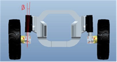
Fig. 2Front suspension cylinder internal structure
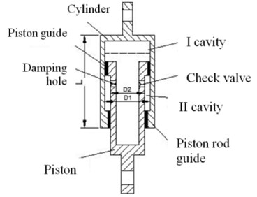
The internal structure of front suspension cylinder is shown in Fig. 2, which is mainly composed of two parts: cylinder and piston rod. The whole cylinder is divided into I cavity and II cavity, the upper part of I cavity is inert gas , the lower part is oil, and the II cavity (annular cavity) is filled with oil. The inert gas acts as an elastic element, and the oil acts as attenuating vibration and absorbing energy when it flows through the damping orifice and the check valve. The piston rod moves up and down along the road surface, so that the gas inside of the hydro-pneumatic spring is in a state of constant compression and expansion.
The piston guide and the piston rod guide play the role of guiding and sealing. The longer the guide portion is, the better its guiding property is. It can avoid the bending force of between the piston and the cylinder tube, decrease the cylinder vibration transmission rate and improve the riding comfortability of vehicles.
3. Experiment
In order to measure the influence of the guide part length of the front suspension on the vibration and the comfort of the vehicle, three cylinders with the guide part length of 0.2 m, 0.3 m and 0.5 m were prepared in this experiment. Test conditions are: no-load operating phase and loading phase.
The pressure sensor and the displacement sensor are respectively installed on the front suspension cylinder, to observe whether appear the pressure step beating phenomenon or “friction locking” phenomenon.
Fig. 3 is no-load operating phase, the pressure and the displacement of the cylinders was measure.
Fig. 4 is loading phase, in this phase we can find the pressure change during the loading phase.
Fig. 3No-load operating phase
Fig. 4Loading phase
The acceleration sensor is installed on the top and bottom of the cylinder. Fig. 5 is installation location of the acceleration sensor. The vibration transmissibility of the cylinder can be evaluated by vibration transmission rate of the cylinder, and the vibration transmissibility of the cylinder is the ratio of the RMS value of the response vibration acceleration to the RMS value of the excitation acceleration. The smaller the value of the vibration transmissibility show that the more the energy absorbed by the damper, the stronger the vibration attenuation and the better the damping capacity of the cylinder.
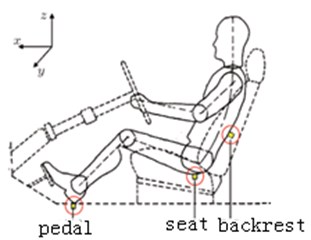
In order to obtain the influence of different guide length of front suspension cylinder on vehicle ride comfort, acceleration sensors are installed on the pedal, seat and backrest respectively, is shown in Fig. 6. Through the data analysis, the total weighted acceleration RMS value can be obtained. By comparing with the ISO 2631-1:1997 (E) standard [11], the vehicle ride comfortability can be obtained according to the different length of the cylinder.
Fig. 5Installation location of the acceleration sensor
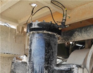
Fig. 6Installation location of the three axis acceleration sensor
4. Result and discussion
4.1. Tables
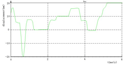
Due to the uneven surface of the road, pressure and displacement are changing during the truck driving process. Fig. 7 is the pressure changes during truck driving, and Fig. 8 is the displacement changes during truck during this process, it can be seen that there is a step-jump phenomenon in front cylinder pressure changes during truck driving, and there is a short time ‘friction locking’ phenomenon between cylinder and piston.
Fig. 7The pressure changes during truck driving
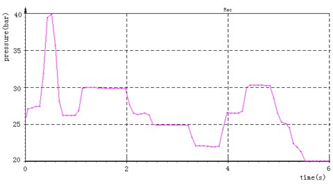
Fig. 8The displacement changes during truck driving
In order to more accurately analyze the vibration damping performance of the cylinder, the loading process was select to study. Because in the loading process, the upper end of the cylinder is the input, and the lower part is the output, which is a single input and multi output vibration, can greatly reduce the influence of the coupling effect.
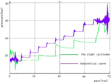
The load of the truck is 72 tons. An 8 tons of shovel was used for loading in this experiment, each vehicle need 9 shovels. During the loading process, the pressure of the cylinder is changed as shown in Fig. 9 and Fig. 10, the length of the guide part of the cylinder in Fig. 9 is 0.3 m, and pressure changes every three shovels, and the pressure changes twice during loading. Fig. 10 corresponds to the front suspension cylinder guide length is 0.5 m, pressure changes every two shovels, and the pressure changes four times during the whole loading process.
It can be seen that lengthening the length of the guide part can improve the ‘friction locking’ phenomenon, can better play the role of vibration absorber and can better protect the frame and tires.
Fig. 9The guide length of the cylinder is 0.3 m pressure changes during loading process
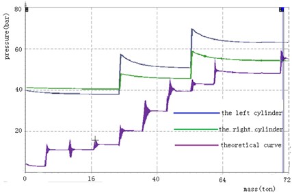
Fig. 10The guide length of the cylinder is 0.5 m pressure changes during loading process
4.2. The vibration transmission rate of the cylinder with different length
The vibration transmission rate is used to measure the vibration reduction capability of the cylinder. During the loading process, the excitation is transmitted from top to bottom, therefore the vibration transmission ratio is the ratio of the RMS value of the acceleration of the lower cylinder to the RMS of the acceleration of the upper cylinder.
The RMS value of vibration response acceleration:
where is the analysis time, is the time-domain signal of vibration response acceleration.
The RMS value of vibration excitation acceleration:
where is the analysis time, is the time-domain signal of vibration excitation acceleration:
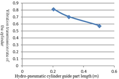
The is vibration transmission rate, and it is a dimensionless value. The smaller value of indicates that the more energy absorbed by the damper, the more vibration attenuation. The vibration transmission rates corresponding to different guide lengths are shown in Fig. 11.
As can be seen from Fig. 11, under the condition of other parameters are fixed, the length of the guide increases from 0.2 m to 0.5 m, the vibration transmissibility of the cylinder changes from 0.82 to 0.58 and the vibration damping of the cylinder increases by 29.3 %.
Fig. 11Different guide part length of the corresponding cylinder vibration transmission rate
4.3. The riding comfortability of the vehicle with different cylinder
In order to analyze the influence of the different guide lengths of the cylinder on the vehicle comfort. In this paper, according to the standard of ISO 2631-1: 1997 (E), the RMS of the total weighted acceleration of vehicle pedals, seats and backrest, and it is used to evaluate the ride comfort of truck:
where for the acceleration spectral density function, for the axial frequency weighting function.
It can be seen from Fig. 12 that the value corresponding to the different guide lengths of the front suspension cylinder.
Fig. 12The total weighted acceleration RMS curve with the length of the cylinder guide
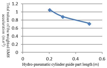
As can be seen from Fig. 12, as the length of the cylinder guide increases, the total of the weighted value RMS acceleration of vehicle decreases. When the length of the guide is 0.2 m, is 1.06 m/s². When the length of the guide at 0.5 m, the value of aw dropped to 0.72 m/s² and the value of decreased by 32.1 %. The riding comfort of the vehicle has been greatly improved. From the trend of curve, the change curve becomes more and more flat, which shows that as the guide part of the total acceleration of the RMS rate is getting smaller.
5. Conclusions
When the structure is fixed, the length of the guide increases from 0.2 m to 0.5 m, the vibration transmission rate of the cylinder changes from 0.82 to 0.58, and vibration reduction capability of the cylinder increases by 29.3 %.
Adopting the method of lengthening the guide part of the cylinder can improve the cylinder pressure “friction locking” phenomenon and improve the ride comfortability of the vehicle. When the length of the guide part is increased from 0.2 m to 0.5 m, the RMS value is reduced by 32 %, and the riding comfortability of the vehicle is obviously improved. From the curve trend, the curve is more and more flat, indicating that as the guide part of the total acceleration of the value change is getting more and more smaller, so there is an optimal guide length according to the specific circumstances of the vehicle.
References
-
Sim Kyuhyun A., Lee Hwayoung A., Yoon Ji Won B., Choi Chanho B., Hwang Sung Ho Effectiveness evaluation of hydro-pneumatic and semi-active cab suspension for the improvement of ride comfort of agricultural tractors. Journal of Terramechanics, Vol. 69, 2017, p. 23-32.
-
Lalitkumar Maikulal Jugulkar, Shankar Singh, Suresh Maruti Sawant Analysis of suspension with variable stiffness and variable damping force for automotive applications. Advances in Mechanical Engineering, Vol. 8, Issue 5, 2016, p. 1-19.
-
Suna Xuemei, Chub Yaxu, Fana Jiuchen, Yanga Qiuxiao Research of simulation on the effect of suspension damping on vehicle ride. International Conference on Future Electrical Power and Energy Systems, Vol. 17, 2012, p. 145-151.
-
Du Heng, Wei Jianhua. Optimization of ride comfort and road friendliness parameters of a hydropower suspension system based on genetic algorithm. Journal of Vibration and Shock, Vol. 8, 2011, p. 133-138.
-
Wei Jianhua, Du Heng, Fang Xiang, Guo Kun Analysis of road friendlyness of hydro-pneumatic suspension based on ADAMS/Simulink/AMESim. Journal of Agricultural Mechanization, Vol. 10, 2010, p. 11-17.
-
Cao Xuyang, Li Zhiyong, Wang Dianlong Simulation analysis of the influence of damping hole size on the performance of connected-type hydro-pneumatic suspension. Construction Machinery, Vol. 6, 2015, p. 63-67+73.
-
Zhen Longxin, Zhang Wenming Simulation and experimental research on single chamber hydrocarbon suspension. Journal of Mechanical Engineering, Vol. 5, 2009, p. 290-294.
-
Xu Daolin, Zhang Lin, Zhou Jiaxi Optimization of hydro-pneumatic suspension parameters for heavy MineDump truck. Journal of Vibration and Shock, Vol. 24, 2012, p. 98-101+107.
-
Yan Fugang Nonlinear modeling of hydro-pneumatic suspension based on ADAMS and Simulink engineering vehicles. Machine Tool and Hydraulics, Vol. 3, Issue 3, 2017, p. 172-176+180.
-
Fang Ying, Li Bo Analysis on the Influence of Independent hydro-pneumatic suspension based on AMESim parameters variation. Machine Tool and Hydraulics, Vol. 4, 2017, p. 133-138.
-
ISO 2631-1: Mechanical Vibration and Shock – Evaluation of Human Exposure to Whole-Body Vibration – Part 1 – General Requirements, 1997.
About this article

The authors would like to thank the guidance from the Professors in Chang’ an University. This paper was supported by Fundamental Research Funds for the Central Universities of China (Nos. 300102258110 and 310825171004).
