Abstract
Reducing of frictional losses between moving parts of drivelines is a permanently current topic for both conventional internal combustion engines and modern hybrid or electric drives. The application of low viscosity oils leads to the reduction of friction losses of moving engine components and thus to low fuel consumption. Further measures to increase efficiency, such as reducing the oil flow rate, must also be taken into account in their effect on functional behavior. All in all, these measures place increased demands on the functionality and durability of engine components such as piston rings and plain bearings. The effects of low viscosity engine oils on piston rings and plain bearings can be evaluated using specific computational tools and newly developed test methods. Another option to reduce the power dissipation in drive units is to use a suitable torsional vibration damper type.
1. Introduction
When designing a torsional vibration damper, it is necessary to carefully check, in addition to the mechanical parameters, the effects of the dissipated power in the damper. The transfer of this power in the form of heat must be ensured. The power dissipation in the torsional vibration damper is a part of the total mechanical losses in the drive unit. Careful selection of an appropriate type of torsional damper can yield a comparable reduction of mechanical losses, as mentioned above in the most recent modification of the piston and sliding bearings.
The modern approach to the optimal design of a driveline with internal combustion engines requires a complex design of the cranktrain, i.e. the organic coupling of the crankshaft, including its classical components, with the damper of torsional vibrations not only as an accessory or supplement, but as an integral part of the whole system.
The solutions used so far are based on the classical idea of using the dynamic damper as a simple additional system connected to the basic system by an elastic and damping element. In the present time the viscous damper is undisputedly the most widely used type of dynamic damper of crankshaft torsional vibrations used on engines of different size and purpose, as shown in Fig. 1. When designing the silicone damper very good accordance between the results of modern computational methods and subsequent experimental verification while respecting the viscoelastic properties of silicone oils can be achieved [1].
In the field of internal combustion engines, no suitable and universally applicable design solution of the dynamic torsional damper with the coupling by the rheological parallel two-parameter model has been developed, which would allow optimal and stable parameters of the viscoelastic coupling and thus a favorable damping effect in accordance with the theoretical analysis and the possibilities of this damper type [2, 3].
One known shortcoming of the rubber damper of torsional vibrations is the substantially lower damping of the rubber element with respect to the optimum value. Difficulties in the design and fears of some engine manufacturers prior to the application of rubber dampers also result from the instability of the mechanical rubber properties caused by manufacturing tolerances, the operating temperature range and the aging of the rubber. Rubber dampers can still be successfully applied to engines of passenger and commercial vehicles, with their perspective also in the replacement of the rubber by another suitable viscoelastic material.
Economic considerations lead in the present time in some cases to replace the silicone damper by the previously applied centrifugal pendulum [3] because of their much lower dissipated power. By integrating a centrifugal pendulum, the damping capacity in the dual-mass flywheel can also be increased by a speed-adaptive component. The centrifugal pendulum is mounted on the flange of the dual-mass flywheel, as shown in Fig. 1.
Fig. 1a) viscous torsional damper [4], b) four centrifugal pendulums (AUDI)
![a) viscous torsional damper [4], b) four centrifugal pendulums (AUDI)](https://static-01.extrica.com/articles/19921/19921-img1.jpg)
a)
![a) viscous torsional damper [4], b) four centrifugal pendulums (AUDI)](https://static-01.extrica.com/articles/19921/19921-img2.jpg)
b)
The above-mentioned conventional designs of the dynamic torsional vibration dampers are unquestionably applied, and they also retain their importance in the future. However, the further development of powertrains, which is characterized both by the increase in operating parameters and by the application of some previously unusual configurations of multi-cylinder engines, also calls for new approaches to the issue of engine dynamics, e.g. the design of principle new systems of vibration damping based on other configurations of masses and elastic and damping couplings of the dynamic vibration dampers.
2. Comparison of vibration dampers in terms of dissipated power
The characteristic features of simple dynamic vibration dampers (see Fig. 2) and their dimensionless parameters are found in the literature [2, 3, 5, 8-11].
Fig. 2Schematic arrangement of the simple torsional vibration dampers
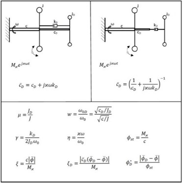
Apart from basic mechanical parameters of the systems shown in Fig. 2, one important factor in comparison is the magnitude of the dissipated energy in the case of an oscillatory movement in the damping element of the viscoelastic coupling of the damper. If one starts from the basic relationship for the energy dissipated per period in a viscous damping element:
Then follows for the energy dissipated per time unit, i.e. the dissipated power:
By using dimensionless quantities according to Fig. 2 in the relationship (2) is obtained after forming for the dimensionless dissipated power:
By substituting the relationship for the magnification function of the angular deformation of the damping element into the Eq. (3) follow the relationship for the dimensionless relative dissipated power [1], as shown in Fig. 3. For different relative damper sizes , the curves of the relative dissipated power are shown in the diagrams in Fig. 3, which correspond to the optimum values of the damper tuning and the damping ratio .
Fig. 3Relative dimensionless dissipated power in damping elements for different relative damper sizes μ at optimal values of the tuning wopt and the damping ratio γopt: a) ΠD=μγη64γ2η2[1-1+μη2]2+μw2η2-η2-1η2-ω22, b) ΠD=μγw4η44γ2μw2η2-η2-1η2-w22+η2w4η2-12, c) ΠD=μγη44γ21-1+μη22+η2η2-12
![Relative dimensionless dissipated power in damping elements for different relative damper sizes μ at optimal values of the tuning wopt and the damping ratio γopt: a) ΠD=μγη64γ2η2[1-1+μη2]2+μw2η2-η2-1η2-ω22, b) ΠD=μγw4η44γ2μw2η2-η2-1η2-w22+η2w4η2-12, c) ΠD=μγη44γ21-1+μη22+η2η2-12](https://static-01.extrica.com/articles/19921/19921-img4.jpg)
a) Damper with two-parameter model in parallel arrangement
![Relative dimensionless dissipated power in damping elements for different relative damper sizes μ at optimal values of the tuning wopt and the damping ratio γopt: a) ΠD=μγη64γ2η2[1-1+μη2]2+μw2η2-η2-1η2-ω22, b) ΠD=μγw4η44γ2μw2η2-η2-1η2-w22+η2w4η2-12, c) ΠD=μγη44γ21-1+μη22+η2η2-12](https://static-01.extrica.com/articles/19921/19921-img5.jpg)
b) Damper with two-parameter model in series arrangement
![Relative dimensionless dissipated power in damping elements for different relative damper sizes μ at optimal values of the tuning wopt and the damping ratio γopt: a) ΠD=μγη64γ2η2[1-1+μη2]2+μw2η2-η2-1η2-ω22, b) ΠD=μγw4η44γ2μw2η2-η2-1η2-w22+η2w4η2-12, c) ΠD=μγη44γ21-1+μη22+η2η2-12](https://static-01.extrica.com/articles/19921/19921-img6.jpg)
c) Viscous damper
From Fig. 3, it is evident that the dissipated power in the viscous damper is considerably larger than that of the dampers whose coupling comprises an elastic component.
It is therefore advisable to look for technical solutions of torsional vibration dampers, which will be more advantageous in terms of their damping effect and power dissipation compared to a viscous torsional damper. To find the structure and parameters of such unconventional solutions, optimization software is an effective tool.
3. Comparison of viscous damper versus rubber twin-damper
A viscous damper and a rubber twin-damper have been developed and experimentally validated for a six-cylinder inline diesel engine [9-13].
Fig. 4Comparison of the damping effect of the viscous damper and rubber twin-damper
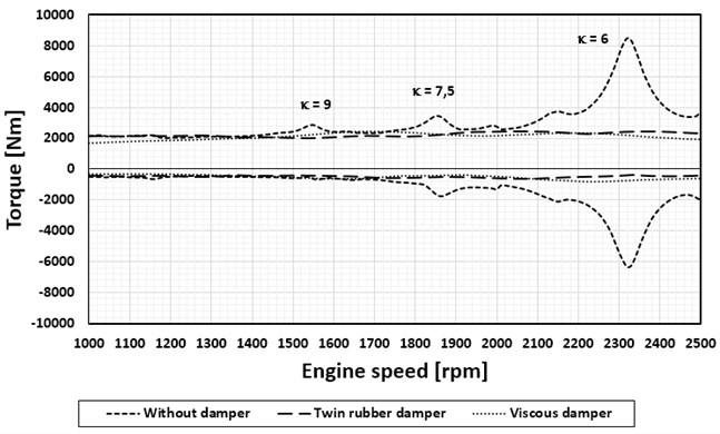
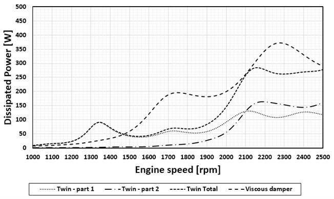
Fig. 5Dissipated power in the viscous damper and rubber twin-damper
In order to find optimal parameters of both types of torsional dampers, dynamic computational models [1] and optimization software were used.
The damping effects of the optimized viscous damper and the torsional rubber twin-damper are illustrated in Fig. 4 for maximum torque values at the crankpin on the flywheel side.
Dissipated power in the viscous damper and in the both parts of the rubber twin-damper is shown in Fig. 5.
4. Conclusions
The application of viscous torsional dampers in larger motors is in terms of their damping effects possible but the dissipated power values are relatively considerable. A better solution in these cases can be a rubber twin-damper which has a significantly lower total dissipated power with a comparable torsional vibration damping effect.
References
-
Píštěk V., Klimeš L., Mauder T., Kučera P. Optimal design of structure in rheological models: an automotive application to dampers with high viscosity silicone fluids. Journal of Vibroengineering, Vol. 19, Issue 6, 2017, p. 4459-4470.
-
Genta G. Vibration of Structures and Machines. Springer-Verlag, New York, 1993.
-
Nestorides E. J. A Handbook on Torsional Vibration. Cambridge University Press, Cambridge, 1958.
-
How Does A Viscous Damper Work? Vibratech TVD Blog, 2018, http://blog.vibratechtvd.com/blog/how-does-a-viscous-damper-work
-
Lewis F. M. The extended theory of the viscous vibration damper. Journal of Applied Mechanics, Vol. 22, 1955, p. 515-552.
-
Tůma J. Vehicle Gearbox Noise and Vibration: Measurement, Signal Analysis, Signal Processing and Noise Reduction Measures. John Wiley, Chichester, 2014.
-
Gupta, A. Numerical Methods using MATLAB. Springer-Verlag, New York, 2014.
-
Porteš P., Kučera P., Píštěk V., Fojtášek J., Zháňal L. Modern tools for vehicle development. Engineering Mechanics, Vol. 2017, 2017, p. 54-57.
-
Kučera P., Píštěk V. Testing of the mechatronic robotic system of the differential lock control on a truck. International Journal of Advanced Robotic Systems, Vol. 14, Issue 5, 2017, p. 1-7.
-
Prokop A., Řehák K. Virtual prototype application to heavy-duty vehicle gearbox concept. Engineering Mechanics, Vol. 1, Issue 2017, 2017, p. 810-813.
-
Drápal L., Šopík L., Vopařil J. Investigation of torsional vibration of unconventional crank train. Vibroengineering Procedia, Vol. 7, 2016, p. 31-36.
-
Medeiros H. S., Pilatau A., Nozhenko O., et al. Microwave air plasma applied to naphthalene thermal conversion. Energy Fuels, Vol. 30, Issue 2, 2016, p. 1510-1516.
-
Mogila V., Vasyliev I., Nozhenko E. The use of biofuel on the railway transport. Transport Problems, Vol. 7, Issue 1, 2012, p. 21-26.
About this article

This work was prepared in the frame of the internal Brno University of Technology Research Project Reg. No. FSI-S-17-4104
