Abstract
Numerous studies have established that the damage to the lower surface of hot-rolled strips is mainly due to their friction against rollers of mill rollers. In this case, the probability of scoring, scrapes and other mechanical damage increases otherwise severe wear on the surface of the rollers, improper installation and jamming. This also applies fully to the pulling and forming rollers of the coilers. On modern broadband mills the following measures are used to prevent damage to the surface of hot-rolled strips: reduce the distance between the axes of adjacent rollers; Increase the accuracy installation of rollers in the horizontal plane; apply the individual drive of each roller; provide a smooth increase in the speed rotation of the rollers along the length of the withdrawing roller table; increase the wear resistance of rollers. A prerequisite for preventing damage to the surface of hot-rolled strips is also the maintenance of a high level technical condition of the mill equipment, which includes inspections of wiring armature bars, roller conveyor rollers and other units for each transshipment, timely replacement and repair of individual parts and assemblies (primarily roller conveyors, interroller plates, etc.).
1. Introduction
In the conditions of sharp and often unpredictable changes in prices for rolled metal and energy resources, the use of innovative technologies in rolling production makes it possible to significantly improve the efficiency of production and consequently the competitiveness of manufactured sheet products [1]. Researching by scientists from the far and near abroad have shown that the temperature conditions for rolling on continuous wide-band hot rolling mills (CWBHRM) and cooling on a retractable roller table are the determining factors for obtaining high-quality rolled products in terms of structure, mechanical properties, and flatness in a variety of thicknesses [2]. In this way, it is paramount to create efficient equipment and technologies that allow to reduce energy and labor costs for rolled products, reduce the consumption coefficients of metal and tools, improve the quality and improve the accuracy of rolled sheets [3]. The solution of these issues depends to a large extent on the reliability of the running roller table. Retractable roller tables are included in the complex of rolling equipment and are quite complex aggregates, consisting a large number of rollers with individual drive [4]. As practice shows, it is their work that causes the greatest number of emergency shutdowns of the mill. This leads to a decrease in rolling capacity, deterioration of the quality parameters of the sheet. In this way, the improvement design of the escaping roller table, aimed at improving the quality of sheet metal, is an urgent task. Numerous studies have established that the damage to the lower surface of hot-rolled strips is mainly due to their friction against rollers of mill rollers. In this case, the probability of scoring, scrapes and other mechanical damage increases in cases of severe wear on the surface of the rollers, improper installation and jamming [5]. This also applies fully to the pulling and forming rollers of the coilers. On modern broadband mills the following measures are used to prevent damage to the surface of hot-rolled strips: reduce the distance between the axes of adjacent rollers; Increase the accuracy of installation rollers in the horizontal plane; apply the individual drive of each roller; provide a smooth increase in the speed rotation of the rollers along the length of the withdrawing roller table; increase the wear resistance of rollers [6]. A prerequisite for preventing damage to the surface of hot-rolled strips is also the maintenance of a high level of technical condition of the mill equipment, which includes inspections of wiring armature bars, roller conveyor rollers and other units for each transshipment, timely replacement and repair of individual parts and assemblies (primarily roller conveyors, interroller plates, etc.) [7]. It should be noted that the rollers of the roller conveyor, is one of the massive elements, is subject to heavy wear and frequent breakages, which leads to significant roller conveyor failures. Only because of the wear and tear of the barrels of the rollers of the CBM-1700 off-road roller conveyor of JSC “Arcelor Mittal Temirtau”, about 280-330 rollers are out of order during the year, which makes up 80 % of the annual roller consumption for the CBM-1700 roller table [8].
Intensification of transportation speeds, ensuring a high quality of the surface strips require a roller of increased performance indicators, the main of which are:
– minimum axial moment of inertia;
– minimization of imbalance due to temperature deformations at one-sided heating;
– ability to resist wear well in friction.
An analysis of numerous literatures shows that the existing approaches to improving the work of the diverting roller tables do not allow for a sharp increase in their performance. In our opinion, a qualitative improvement in the movement of hot-rolled strips can be achieved only with the use of roller conveyors of a fundamentally new design, for example, using the air cushion principle in rolling production. Consequently, ensuring the reduction of roller wear by applying a fundamentally new design of the take-off roller table is an urgent task.
2. Materials and methods
Rollers are the most important details of a leading roller table. The pressure that occurs during transportation of the sheet by the outgoing roller conveyor is perceived by the rollers. Therefore, in the design and manufacture of rollers, special attention is paid to their strength and rigidity [1]. The initial data for the calculation are the solid-state geometric shape of the section of the withdrawing roller table, the fixing conditions and the forces applied to the transported sheet and the rollers of the take-off roller table. In the calculation, the geometrical and finite element model of the calculated section, the fixing conditions, the application of forces to the transported sheet and the calculation of the stressed-deformed state rollers and the strength rollers of the guide roller are constructed. The calculation method is implemented using the Autodesk Inventor finite element analysis program. The system of computer modeling Autodesk Inventor allows you to explore the kinematics, the dynamics of mechanisms with the ability to calculate the stress-strain, both individual elements and the design as a whole [2].
The assembling three-dimensional geometric model of a retractable roller table was built in the CAD program of Inventor. For the possibility of automatic correction geometry of the escaping roller table the method of parameterization of the geometric dimensions of the structure was used. This method allows, based on the strength calculation results, to make appropriate changes to the design of the take-off roller table [3]. Thus, in the course of the preliminary analysis work of the outrigger roller table, the most loaded power element of the outgoing roller table was taken into account, like a roller. From the lower part of the outgoing roller conveyor to the transported strip, air with high pressure directed from the fan acts. This allows you to reduce the amount of vertical forces that occur on the rollers when the strip moves along the outgoing roller table. As a material for the commercials, the Autodesk Inventor steel of the grade-35c was selected from the Autodesk Inventor steel database of mechanical properties: the Young’s modulus of 200 GPa, the strength of 420 MPa, and the Poison coefficient of 0.3.
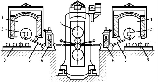
Fig. 1Scheme of the Steckel mill with coilers in the furnace: 1 – bell-furnace; 2 – oven-winder; 3 – roller table; 4 – quarto stand; 5 – postings; 6 – pulling rollers
3. Results and discussion
The results of the study distribution of stress-strain state during the transportation of a strip 12 mm thick on a discharge roller table with lower air pressure and without air pressure are presented in Figs. 2-6 and Figs. 7-12 respectively.
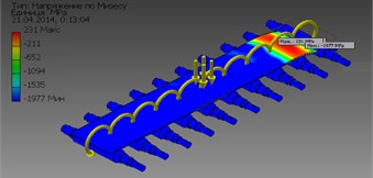
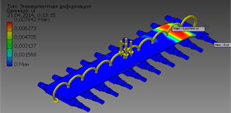
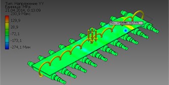
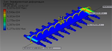
Fig. 2The pattern of the distribution of equivalent stresses a) and deformations b) in rollers during the transportation of strips in a roller table without lower air pressure
a)
b)
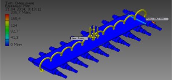
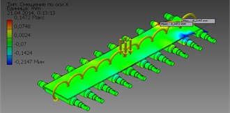
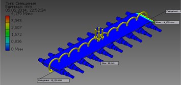
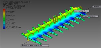
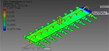
Fig. 3The pattern of the distribution of the total displacement a) and the displacement along the X b) axis in the rollers during the transportation of the strips in the roller table without lower air pressure
a)
b)
The performed calculations showed that:
– Equivalent stresses and deformations, total displacements, stress tensor and deformation components during the transportation of the strip in the outgoing roller conveyor with the lower air pressure significantly decreases [4]. Decrease in the value of equivalent stresses and deformations leads to a significant decrease in wear and breakage of rollers, while the failure of roller tables will be very rare.
– When the belts are transported in a roller with lower air pressure, the maximum values of the equivalent stresses 153.771 MPa, (see Fig. 7(a)) and the deformation 0.000693656, (see Fig. 7(b)) do not exceed the maximum permissible value for the given material of the strength of 640 MPa. In this case, the values of equivalent stresses and deformations are considerably less than the equivalent stresses 231.1 MPa, (see Fig. 2(a)) and deformations 0.00784182, (see Fig. 2(b)), obtained by transporting strips without lower air pressure.
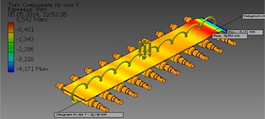
– When transporting strips in a roller with lower air pressure, the maximum value of the displacement along the axis (0,0395345 mm), along the axis (0,541817 mm) and along the axis (0,194713 mm) is much smaller (see Figs. 11-12), in comparison with the -axis offsets (0,147172 mm), along the -axis (8,49907 mm) and along the -axis (3,8522 mm) obtained during the transportation of the strips without lower air pressure (see Figs. 4-5).
Fig. 4The distribution pattern is the displacement along the Y a) and Z b) axes in the rollers during the transportation of the strips in the roller table without lower air pressure
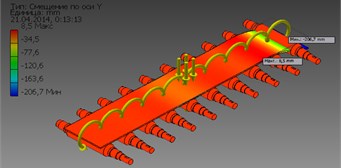
a)
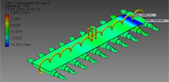
b)
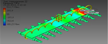
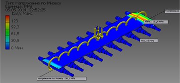
Fig. 5A pattern of the distribution of the components of the stress tensor σxx, σyy, and σzz in rollers during the transportation of strips in a roller table without lower air pressure
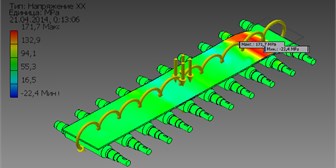
a)
b)
c)
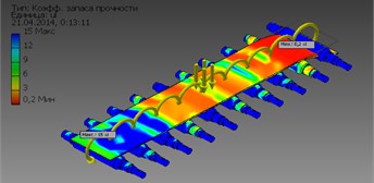
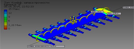
Fig. 6The distribution pattern of the safety factor in rollers during the transportation of strips in a roller table without lower air pressure
– The maximum values of the stress tensor components obtained 67,4703 MPa, 30,2311 MPa, 171,48 MPa, 5,2 MPa, 5,2 MPa, 2,52 MPa, deformation ( 0,000300224, 0,000276757, 0,000798972, 0,000197073, 0,000133513, 0,0000738653, Do not exceed the maximum permissible value for this material strength value 640 MPa. In this case, these values of stresses and deformations have a value much less in comparison with the stresses 132,9 MPa, 129,9 MPa, 293,9 MPa, 15,1 MPa, 17,7 MPa, 4,09 MPa, (see Fig. 5), deformations 0,000955311, 0,00360929, 0,000798972, 0,000721088, 0,000510976, 0,000340595 when transporting lanes without lower air pressure.
Fig. 7The pattern of the distribution of equivalent stresses a) and deformations b) in rollers during the transportation of strips in a roller conveyor with lower air pressure
a)
b)
Fig. 8The pattern of the distribution of the total displacement a) and the displacement along the X b) axis in the rollers during the transportation of the strips in the roller conveyor with the lower air pressure
a)
b)
Fig. 9The distribution pattern is the displacement along the Y a) and Z b) axes in the rollers during the transportation of the strips in the roller conveyor with the lower air pressure
a)
b)
Fig. 10The distribution pattern of the safety factor in rollers during the transportation of strips in a roller conveyor with lower air pressure
Calculations carried out on finite-element models showed that:
– The maximum equivalent voltage in the roll barrel is 27.5 Pa, and for the neck of the rollers –24.4 Pa of the proposed roller conveyor. And the maximum equivalent voltage occurs in the roll barrel. The resulting maximum values of equivalent stresses (27.5 Pa) do not exceed the maximum allowable value for the material of rollers 420 MPa.
– Under the influence of applied vertical forces, the rollers elastically bend in the direction of the force, and the neck of the rollers elastically deforms in the same direction [5, 6], the maximum value of the equivalent deformation being for the roll of rollers 8,217Е-011, and for the neck of the rollers –7,061Е-011 of the proposed outgoing roller conveyor.
– The largest values of total displacements are concentrated in the non-drive side of the rollers of the outgoing roller conveyor. The maximum value of the movement is 1.49159Е-006 mm.
– As a whole, the value elastic deformation of the elements of the rollers is small, which indicates a decrease in the effort of the proposed outgoing roller table produced on the rollers [7, 8]. This guarantees the possibility of reducing wear and breakage, as well as the failure rollers of the proposed roller conveyor.
4. Conclusions
1) The distribution safety factor pressing mechanisms of the first three stands of the new mill satisfies the strength condition (the calculated margin of safety does not exceed the accepted safety factor of safety).
2) The projected cushions, gear wheels of the first three stands of the multifunctional mill have sufficient safety factor.
3) The results of calculations using the analytical method and using the program COMPAS 3D, Autodesk Inventor are quite consistent. The discrepancy between the values of the determined values does not exceed 5-7 %.
4) A new design of a continuous roller conveyor for continuous mills was proposed and constructed.
5) It is shown that the maximum values of effective stress and strain do not exceed the maximum permissible value for the material of rollers.
6) It is proved that the maximum stress and strain concentrations are observed in the barrels and neck of the rollers and the maximum value of displacement is observed in the non-drive side of the rollers of the outgoing roller conveyor.
7) It is proved that when the belts are transported on a new retractable roller table due to a significant reduction in the metal pressure on the rollers, the value of its elastic deformation decreases. This guarantees the possibility of reducing wear and breakage, as well as the failure rollers of the proposed roller conveyor.
References
-
Tang Yadong, Yu Yongchang, Shi Jingzhao, Zhang Shuaijun Modal and harmonic response analysis of key components of robotic arm based on ANSYS. Vibroengineering Procedia, Vol. 12, 2017, p. 109-114.
-
Shahin Hasanov G., Vagif Mirsalimov M. Modeling of stress-strain state of road covering with cracks. Acta Polytechnic Hongarica, Vol. 11, Issue 8, 2014, p. 215-234.
-
Rybak L. A., Getman Y. A., Shipilov I. P. Research model robot-hexapod under static and dynamic loads. Vibroengineering Procedia, Vol. 8, 2016, p. 527-530.
-
Hasanov Sh G. Modelling of stress-strain state in road covering. Azerbaijan Architecture and Building University, Baku, Vol. 2, 2007, p. 151-159.
-
Dipali Waghulade G., Kolhe S. I. Optimization of work roll chock and backup roll chock in cold rolling mill. International Journal of Advanced Technology in Engineering Science, Vol. 4, Issue 7, 2016, p. 40-49.
-
Portman N. Application of neural networks in rolling mill automation. Iron and Steel Engineer, Vol. 72, Issue 2, 1995, p. 33-36.
-
Asch A., Hohn W. Monitoring system for roll stand drives using strain gage technology. Automation in Mining Mineral and Metal Processing, 1999, p. 159-164.
-
Dragomir S. Monitoring of iron sheet deformation in the rolling mill process by using CVC system. Proceedings of XII International Metallurgy Materials Congress, Istanbul, Turkey, 2005, p. 843-847.
-
Radu T., Potecasu F., Vlad M. Research on obtaining and characterization of zinc micro-alloyed with bismuth coatings. Metalurgia International, Vol. 1, 2011, p. 44-48.
About this article

