Abstract
The purpose of this study is to develop a stent motor for medical blood vessel treatment. The stent motor is a movable stent. It has functions of removing plaque and expanding blood vessels. It consists of two parts; ultrasonic receivers and vibration transmitting coil (stator). In this study, the authors have focused to the vibration analysis of the receiver. In the first design stage, the authors have evaluated resonant phenomenon using finite element method. When driving it in water, the resonant frequency of the air use is shifted due to mass effect of water around the receiver. The frequency analysis of the receiver shows that extremely high precision of dimensions is required because the resonant frequency in water depends not only the size but also the amplitude of the vibration. It is very difficult to design an optimal receiver resonating in water. In order to solve this problem, the authors have tried a new receiver with wide plate receiving ultrasound effectively and requiring no resonant. The authors have succeeded in driving this type of motor in water.
1. Drive principle of stent motor
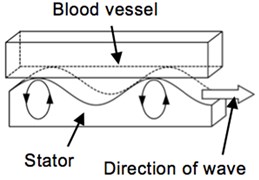
The stent motor consists of a receiver and a coil (stator). The receiver receives energy of the ultrasonic wave vibration in water generated from the outside vibration source. The stator is a coil shape and transmitting the energy in the form of travelling wave. At the top of amplitude of travelling wave, frictional force (driving force) is generated between stator and blood vessel to drive itself. The authors have two models; one is based on resonant phenomenon and the other is based on ultrasonic impact.
The motor mechanism is as follows; a vibration source generates ultrasonic to a human body from outside. The vibration wave is propagating through the body to the motor receiver. The motor receiver starts vibrating with principal vibration mode and inducing traveling wave along the coil (stator). The coil and blood vessel is pressed each other with proper force. The travelling wave generates frictional force at the top of the wave amplitude. It works as driving force to rotate the stent (blood vessel is stationary) [1-4].
Fig. 1Over view of stent motor
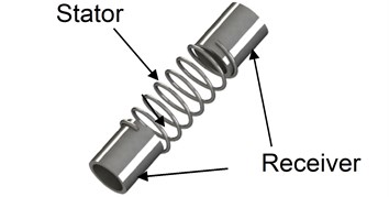
Fig. 2Ultrasonic motor
2. Resonant type of stent motor
2.1. Characteristics of Langevin transducer
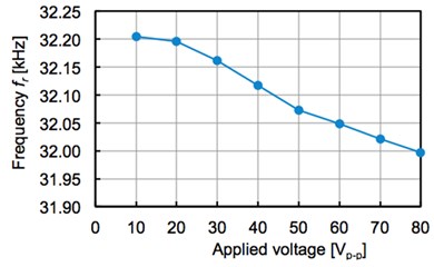
The authors have used bolted Langevin transducer as the vibration source. When applying alternating voltage at the resonant frequency to the Langevin transducer, it generates the large amplitude of vibration. However, the resonant frequency is not constant and changing with applied voltage.
The horn top part of Langevin transducer is set to the 5 mm under the surface of water and the applied voltage is set as 80 Vp-p. The relationship between drive time and a resonant frequency is shown in Fig. 3. A resonant frequency keeps falling from starting to the static state in about 56 minutes. At the static state, the power consumption is 10.32 W and the resonant frequency is 31,997 Hz. When increasing applied voltage, the resonant frequency is changing as shown in Fig. 3. The resonant frequency is falling with rise of voltage.
Fig. 3Frequency and applied voltage
The authors have measured vibration by an impedance analyzer to find that resonant frequency is 32.08 kHz and anti-resonance frequency is 33.21 kHz. Based on it, the electromechanical coupling coefficient is derived to be 0.2849; the maximum mechanical energy transmitted from input electric power is 2.94 W.
2.2. Additional mass effect of water
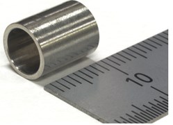
Generally speaking, when an object vibrates in the liquid, the resonant frequency is different from that in the air because it vibrates with near-area water. When installing a receiver in water and applying the supersonic of the 32 kHz, the authors have known the exact size of the receiver is necessary to make resonant from former study. The receiver resonating in the water in this case, is shown in Fig. 4 and Table 1.
Fig. 4Cylindrical type receiver
The authors have made finite element model of the receiver and set mass density from 10 g/cm3 to 12 g/cm3, and simulated vibration eigenvalue. When mass density is set be 11.24 g/cm3, the natural frequency is coincidence with the frequency of the 32 kHz. It indicates that the mass density should be added by 3.21 g/cm3 (mass density of SUS304 is 8.03 g/cm3). In this research, 11.24 g/cm3 is applied to finite element model as the mass density in water.
Table 1Dimensions of receiver resonated in water
Length [mm] | Outside diameter [mm] | Inside diameter [mm] |
10.00 | 8.00 | 6.41 |
2.3. Frequency response analysis of the cylinder type receiver
The authors have made a dynamic model of the cylinder type receiver [5, 6]. The pressure load is added on the surface as acoustic pressure of finite element method. Mass density is 11.24 g/cm3. The wavelength of the supersonic is longer enough than the size of the receiver, so the unit load (1.0 N/mm2) is added to a cylinder receiver. A frequency response is analyzed by a frequency bandwidth of the surrounding 3 % about 99 points in the center of resonant frequency 31997.15 Hz (median). The response is shown in Fig. 5. It shows that the maximum amplitude of vibration (2.57x is 10-7 mm) is obtained in the resonant frequency 31997.15 Hz. On the other hand, the amplitude of vibration (1.39×10⁻⁸ mm) is observed in frequency 31037.23 Hz at a negative side edge of the measuring range. So, the gain of the amplitude in non-resonance and resonant is 18.5. This is the effect of resonant phenomena.
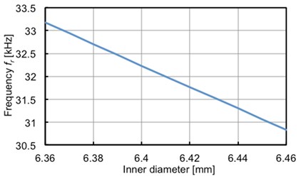
Fig. 6 shows the relationship between the inside diameter of the receiver and resonant frequency simulated by finite element method. As the diameter is larger, resonant frequency is decreasing linearly.
It is very difficult to coincide the frequencies of the vibrator and the receiver because of water effect and processing accuracy.
Fig. 5Frequency response analysis
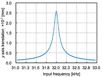
Fig. 6Relationship of resonant frequency and inner diameter
3. Impact type stent motor
The authors have also designed a stent motor with a discus type receiver. Compering with the cylindrical type, this is easier to receive ultrasonic. The discus type receiver’s thickness is 0.1 mm and the diameter is 11.0 mm. The stator has coil shape; the diameter of the coil wire is 0.4 mm, pitch 1.57 mm, 7 turns, the outside diameter 11 mm. The receiver is bent vertically and connected to the coil. It uses no resonant phenomenon. The finite element model is shown in Fig. 7 and 8.
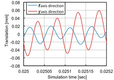
The sine wave pressure of 20 kHz and 1.0 N/mm2 modeled on acoustic pressure is applied to this model’s receiver surface. The finite element model simulates time domain response. The interesting node point is Node S in Fig. 7 (Node S = (0.0630684, 5.499638, –7.199356)). This point is located on the surface where it makes contacts with blood vessel. An analysis results are shown in Fig. 9 with respect to the displacement of Node’s and direction.
The wave along -axis and -axis draws sinusoidal curve with 129.8 degree phase difference. It indicates that the Node draws elliptical motion and this motor may work as an ultrasonic actuator.
Fig. 7FEM model
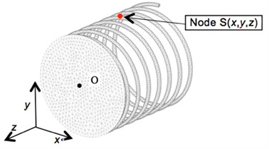
Fig. 8Discus type stent motor
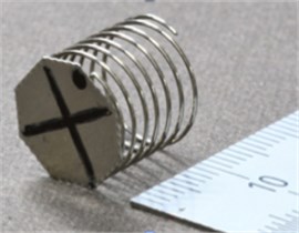
Fig. 9Vibration in x-axis and y-axis
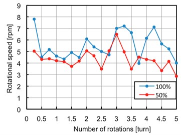
The authors have made experiments of it in water (Fig. 10). The motor is made of SUS304 and the receiver (diameter 4.8 mm) and the coil (20.0 mm length) are connected by solder. As a blood vessel model, MC nylon block with nut shape through hole in the center is adopted. The overview is shown in Fig. 10. The authors have controlled the wattage of Langevin vibrator to drive it in water. The rotational speed at every turn is shown in Fig. 11. It is rotating with rate of 5.28 rpm and 4.19 rpm in the case of irradiating 70 W (100 %) and 35 W (50 %), respectively.
Fig. 10Experimental apparatus
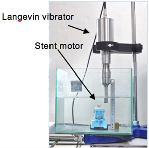
Fig. 11Rotational speed in water
4. Conclusions
The authors have concluded as follows.
1) The stent motor using resonant frequency requires high accuracy in design and processing. The accurate stent motor has good resonant characteristics in water. It shows high potential about use in water.
2) The stent motor using impact is easy to use in water. It shows good maneuverability in water.
References
-
Mashimo T., Toyama S. Development of the translational and rotational piezoelectric actuator using a single stator (1st report)-design of the stator by finite element method analysis. Journal of the Japan Society for Precision Engineering, Vol. 74, Issue 3, 2008, p. 292-297.
-
Hoshina M., Mashimo T., Fukaya N., Matsubara O., Toyama S. Spherical ultrasonic motor drive system for pipe inspection. Advanced Robotics, Vol. 27, Issue 3, 2013, p. 199-209.
-
Mashimo T., Toyama S. Vibration analysis of cubic rotary-linear piezoelectric actuator. IEEE Transactions on Ultrasonics, Ferroelectrics, and Frequency Control, Vol. 58, 2011, p. 844-847.
-
Mashimo T., Toyama S., Ishida H. Design and implementation of a spherical ultrasonic motor. IEEE Transactions on Ultrasonics, Ferroelectrics, and Frequency Control, Vol. 56, 2009, p. 2514-2521.
-
Chen S., Mulgrew B., Grant P. M. A clustering technique for digital communications channel equalization using radial basis function networks. IEEE Transactions on Neural Networks, Vol. 4, 1993, p. 570-578.
-
Ferreira P. A. M. High-performance load-adaptive speed control for ultrasonic motors. Control Engineering Practice, Vol. 6, Issues 1, 1998, p. 1-13.
About this article

