Abstract
In order to improve the signal natural frequency of dynamic vibration absorber and eliminate the influence of nonlinear output force to the adaptive vibration absorption system. A new type of electromagnetic active vibration absorber is designed in this article. The internal magnetic circuit structure is changed through the electromagnet placed on the upper and lower, produce the electromagnetic force in two directions. Reaction force of upper mass is used to eliminate the target vibration. The effective frequency range of the vibration absorption increases, output force is basically linear. Aimed at multiple-point adaptive control strategy, a distributed multi-channel adaptive control algorithm is proposed, in which coupling between channels can be compensated on each control loop. Influence of secondary path on active control is analyzed, put forward the improved least mean square algorithm to identify the secondary. Active vibration control experiment platform is structured to verify the output force of absorber, and engineering application of the distributed multi-channel adaptive control algorithm. The results show that the distributed multi-channel adaptive control algorithm system has about 15 dB noise reduction, effect is obvious; new type of electromagnetic active vibration absorber is not limited to the natural frequency, output force can adaptive keep pace with the excitation frequency.
1. Introduction
Vibration absorption is an important branch in the field of vibration engineering. According to the realization method, it can be divided into passive vibration absorption, semi-active vibration absorption and active vibration absorption. Power absorber is easy to be implemented and has obvious effect, so it’s widely used in the transportation, industrial machinery and bridge construction [1-6]. Absorption of vibration is a widely used decreasing vibration technology. It has been more than one hundred years since the first DVA (Dynamic Vibration Absorber) was invented in 1902. The principle of vibration absorber is energy transfer, in other words, the vibration of the target structure is canceled by the resonance of the absorber vibrator. Because its structure is simple, and it also can effectively control the vibration of the structures and the equipment which frequency changes in a small range effectively, the DVA has become the effectively control instruments for the vibration control. But a passive dynamic vibration absorber has a great limitation to the effective frequency of passive absorber is signal only the inherent frequency [7]. Besides, the small power absorber may not be adaptive to smooth operation because of large amplitude. The active dynamic vibration absorber can overcome above problems efficiently. The principle is to change the feature of elastic component or inertia components included in the absorber through special algorithm. Then the output of the absorber is to be changed as a certain algorithm through actuators contained in the absorber [8]. According to the principle of work and design criterion of DVA, there are two types of the active dynamic vibration absorbers: frequency-nonadjustable DVA and frequency-adjustable DVA.
At present, the urgent problem to be solved is the nonlinear compensation for the active vibration absorber [9, 10]. The regular control method is the linear approach algorithm that highly depends on the accurate model of the absorber. However, the accurate model is difficult to be identified, which will result in the negative impact on control, because the non-linear effect cannot be compensated completely in the actual control system [11-14]. Many related researches had been carried out before. The semi-active series TMD (Tuned Mass Damper) implemented by Prof. Lei Zuo in Virginia Tech, through replacing the viscous damping element between the two auxiliary masses with an electromagnetic transducer [15]. The electromagnetic shunt damping vibration isolators (EMSD-VLs) were designed for the first-order and third-order vibration, by Dr. Bo Yan, Zhejiang Sci-Tech University [16]. The influence between Tuned mass absorbers and damped structures et al. [17].
In order to reduce the influence of the nonlinear error, a new electromagnetic active vibration absorber is designed by optimizing the magnetic circuit structure. The output force of electromagnetic active vibration absorber can change with the input current linearly. Many vibration absorbers and error sensors are needed to expand the damping range in the actual control system. The increase in quantity brings complicated calculation and impact of channel coupling on control system. So, distributed multi-channel adaptive control algorithm is designed to solve above problems, and has achieved good vibration absorption effect in the experiment.
2. Design of electromagnetic active vibration absorber and characteristic analysis
2.1. Design of structure
Electromagnetic active vibration absorber is a typical active inertial actuator, the structure is as shown in Fig. 1.
In the mechanical structure, electromagnetic actuators are used to change the output force, including passive device consisted of springs, weights and actuating elements [15]. The coil is used as stator and the soft iron with permanent magnets on the upper and lower end is used as mover that clearance fit with middle pillar. The spring is multifunctional part in the absorber. First, it can provide sufficient axial elasticity for the mover of vibration absorber; second it can ensure sufficient radial stiffness when the mover is reciprocating. The resonant frequency of the electromagnetic actuator is determined by the weight of counterweight and the mover mass of actuating element [16], which in turn makes influence on the peak output and operating frequency of electromagnetic actuator.
Fig. 1Electromagnetic active vibration absorber
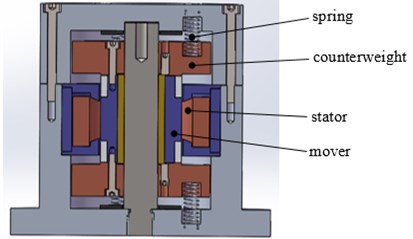
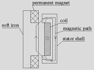
Fig. 2Model of magnetic circuit
2.2. Magnetic circuit analysis and calculation of output force
Model of magnetic circuit is as shown in Fig. 2.
In the model of magnetic circuit, the magnetic potential of upper permanent magnet increases, but decreases in the end permanent magnet. Thus. the soft iron will be in upward force on the support column along the vertical direction, the force in horizontal is canceled by each other. The meanings and symbols of related parameters are shown in Table 1.
Table 1Magnetic circuit parameters and symbols
Parameter | Symbol | Parameter | Symbol |
Winding | current | ||
Length of permanent magnet | Sectional area | ||
Upper coercive force | Upper error magnet | ||
Lower coercive force | Lower error magnet | ||
Air gap of armature | Magnetic resistance of air gap |
Equivalent magnetic circuit method is used to analyze the magnetic circuit model, as shown in Fig. 3.
Fig. 3Equivalent magnetic circuit
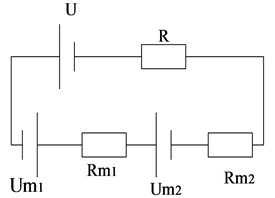
The magnetic potential and magnetic resistance are the equivalent magnetic circuit of permanent magnet on the upper end of the soft iron. The magnetic potential and magnetic resistance are the equivalent magnetic circuit of permanent magnet on the lower end of the soft iron. The magnetic potential of control coil is , here , magnetic resistance of air gap is . Permanent magnet’s materials are NdFeB (neodymium iron boron), so the demagnetized curve is basically a straight line. The formula is as follows [17]:
Magnetic resistance of air gap can be expressed as , is used as the magnetic area of a permanent magnet, is used as air permeanility. If the magnetic resistance, leakage of the magnetic yoke and iron core are ignored, the magnetic fulx of iron core magnetic route can be calculated as [18]:
The electromagnetic force on iron core is:
The electromagnetic active vibration absorber designed in this article can provide electromagnetic force in both directions through the electromagnets in upper and lower of soft iron, without applying the bias current. Because of this unique design, the relationship between input current and nonlinear electromagnetic actuator output can be approximately linear.
3. Distributed multi-channel adaptive control algorithm
3.1. Influence of identification error on control
The error signal will be influenced by secondary path, which in turn affects the convergence criterion. The adjustment of control vector according to control algorithm may not be in the steepest direction of the gradient. The adaptive control process is affected or even failed. So, the accurate identification model is the basis of control. Parameter identification is essential to get the transfer function of secondary path. Considered by the vibration absorption platform and good performance of actuator’s output force, the transversal filter is acted as identification model. The transfer function of secondary path is approached by updating the weight coefficients of identification filter.
Fig. 4Schematic diagram of secondary path identification
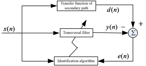
There is always be the identification error between the estimated model and the actual transfer function . S. Snyder and C. Hansen found that when the reference signal is sinusoidal signal, the LMS (Least Mean Square) algorithm converges with a sufficiently small step size, so long as the phase difference between the secondary path identification model and actual transfer function is not more than 90 degrees. The following is the analysis of identification error from the control effect, stability of algorithm and convergence.
The objective function can be expressed as [19]:
where is the autocorrelation matrix of the filtered reference signal, . is the correlation matrix of the desired signal and the filtered reference signal, .
Filtered reference signal is . In order to get the minimum value of the objective function, take the derivative of the objective function:
The optimal coefficients of adaptive control filter can be calculated as follows, substituted into objective function to get the minimum value:
The optimal coefficients are substituted into objective function, the minimum value is:
where is positive definite quadratic matrix, so 0. It shows that the total power of error signal after convergence is lower than that of desired signal.
However, the actual transfer function of secondary path is unknown and difficult to be calculated. So, in the actual control system, the estimation model acted as actual transfer function is used to update the weight coefficients of control filter. At this time, the optimal coefficients is:
The new optimal coefficients are substituted into objective function and the minimum value of it is:
In the Eq. (9), if the identification error is big, it can be inferred that even if the algorithm converges, the total power of error signal may still be higher than that of desired signal. The control fail.
Because of the identification error, the convergence step of LMS algorithm is as follows:
The error signal is directly influenced by estimation model, and the range of iteration step is also affected. Above all, it can be concluded that the accurate estimation model of secondary model is the prerequisite for the convergence of control algorithm. The inaccurate estimation model will lead to the control system in the risk of divergence.
3.2. Identification algorithm of secondary path
The vibration absorption platform is the research object in this paper. The characteristic frequency of platform is not changed greatly, and the output force of absorber is nearly linear, so transversal filter is selected as the estimation model to approach the actual transfer function of secondary path. The transversal filter is a finite impulse response filter, which does not need feedback and past related output. It is non-recursive and commonly used. The nest is the design of identification algorithm, which is expected to improve the identification accuracy as much as possible and reduce the influence of identification error on control system.
The least squares algorithm is introduced in this paper. Convergence speed and steady-state error are influenced by iterative step to some extent in the algorithm. But these two indexes requirements for iterative step is contradictory. When the iterative step is large, the convergence speed is fast, but the steady-state error is large, and vice versa. Variable step method is introduced in this paper. In the beginning of identification, large step is used to ensure fast convergence speed. After the algorithm tends to stabilize, small step is changed to obtain small steady-state error. Update of weight coefficients are as follows:
The key of this algorithm is the step-change mechanism, this to say, the selection of . According to the existing research, the step-change mechanism is roughly divided into two directions: First, Build the relationship between iterative step and error signal of transversal filter. Second, build the relationship between iterative step and gradient vector. In this paper, the change of iterative step is based on identification error.
The frequently-used normalized variable step algorithm is as follows:
where, is initial step, is the tiny positive, which prevents the system diverging. Because the denominator may become zero without the tiny positive. While, the influence of identification error on algorithm is not reflected in Eq. (12). So, a new improved variable step identification algorithm is proposed in this paper. Combined with the above requirements, the change mechanism is changed as:
In the Eq. (13), is the power of identification error, . It can be seen from the Eq. (13) that identification error is large at the beginning of the identification, so the value of variable step is large to get the fast convergence speed. But there is a necessary condition, the initial step must meet the requirement for convergence. And then, the identification error is getting smaller with the updating of weight coefficients, small variable step is changed into identification to obtain small steady-state error. The improved variable step identification algorithm not only ensures the convergence speed of identification, but solves the problem of identification accuracy. The variable step may be too large duo to the pulse impulsion in the process of identification, it should be limited in the convergence range. If , then . Here, is the upper limit of convergence step.
The force diagram of vibration absorption platform is as shown in Fig. 5.
The normalized variable step algorithm and improved variable step identification algorithm are respectively used in the identification of secondary path. The length of transversal filter is 300. The estimation models are as shown in Fig. 6, each line represents an iterative process of a particular filter coefficient.
Fig. 5Force diagram of vibration absorption platform
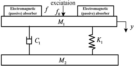
Fig. 6Identification of secondary path with different algorithm
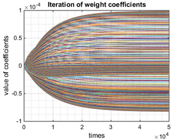
a) Identification with normalized variable step
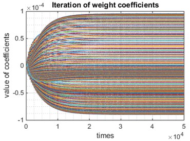
b) Identification with improved algorithm
In Fig. 6, the convergence speed with improved algorithm is faster than that with normalized variable step. It is shown that the improved variable step algorithm could be well applied in the identification of secondary path.
3.3. Multi-channel control algorithm
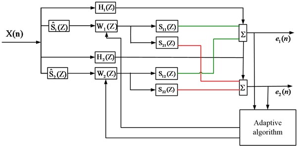
In addition to implement of control system, multi-channel vibration absorber algorithm has no essential difference compared with single-channel algorithm. First, the calculation is greatly complicated with the increase in the quantity of error sensors and vibration absorbers in the multi-channel control system. Second, each error signal collected by sensors is the effect of all vibration absorbers not a single one. So serious coupling between different channels will decrease the stability of control algorithm in the actual control system. The multi-channel control system discussed in this article includes one reference sensor, electromagnetic active absorbers and error sensors. FIR filters with length work as response function of error channel, the quantity of filters is . In order to expound the principle of control system clearly, one reference sensor, two electromagnetic active absorbers and two error sensors are included in the algorithm flow graph.
Fig. 7Multi-channel algorithm flow graph
The reference signal becomes a diagonal matrix:
Here, every vector .
Desired signals work as transfer function of primary path.
Weight coefficients matrix of control filter shown as follow:
where the single weight coefficients .
The output matrix of controllers is:
The output of a single controller at a certain moment work as , and each output signal is in the form of vector, in other word .
acted as transfer function matrix of secondary path, its dimension is :
where represents the transfer function from the control signal to the error sensor. Then the error signal is supposed to be:
The objective function here can be expressed as:
According to convergence rule, calculate the gradient-descent direction:
The weight coefficients of multi-channel controller update as follow formula:
In the Eq. (11), is the result of filtering where the reference signals are filtrated by secondary path matrix, the details are as follows:
The estimation model of secondary path can be expressed as:
The secondary path estimation model matrix must be spilt for the realization of the distributed multi-channel adaptive control algorithm. For example, the secondary path estimation model of dual-channel control system is as follows:
Estimation model matrix must be put into respective channel for the realization of algorithm, so the estimation model of each channel can be expressed as follows:
and are compensation for channel 1 and channel 2 in the actual control system. At the same time, excessive output of some controllers will result in damage to the vibration absorber, So the leakage factor is introduced to limit the output of the controllers in the actual control system.
4. Test of output force and control experiment
4.1. Output force characteristics of electromagnetic active vibration absorber
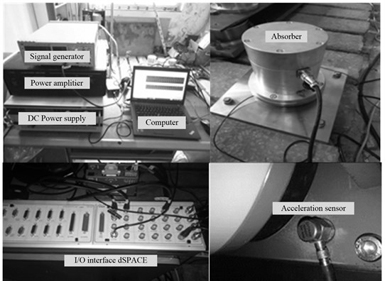
In this article, electromagnetic active vibration absorber is designed, simulated and experimental analyzed. Specific implementation method is included. The force sensors are used to collect vibration signals, the excitation current with different frequency and amplitude. The output force can be calculated according to the signals. The main experimental equipment are as follows in Fig. 8.
EM1643V function signal generator, adjustable frequency range is 0.2 Hz to 2000 Hz, JiangSu JiuNeng Electronic Technology limited company. LA-200 Power Amplifier, drive the vibration exciter, manufacturer is JiangSu LianNeng Electronic Technology limited company. WYK-20040K DC Power supply, output voltage: 0-200V; Current: 0-40A., JiangSu LianNeng Electronic Technology limited company. dSPACE controller, 20 input channels and 8 output channels, manufacturer is Germany dSPACE Company. PCB acceleration sensor, manufacturer is PCB Piezoelectric Sensor Technology (BeiJing) limited company. T460 Thinkpad, Lenovo, used for calculation. The absorbers used in experiment are self-developed and designed.
The frequency of exciting current is respectively 30 Hz, 80 Hz, 100 Hz, 150 Hz and 200 Hz. Variable control method is applied in the experiment. The current is limited in some certain frequency, then change the amplitude to get the output force. The details are given in Fig. 9.
Fig. 8Experimental equipment
As shown in Fig. 9(a), no matter the frequency is 30 Hz around the natural frequency or 200 Hz away from the natural frequency, the output force of absorber changes with the coil current approximate linearly. That is to say, the absorber is driven by a signal frequency current, output force will be a primary frequency, without too much other frequency caused by absorber. Fig. 9(b) shows that output force decreases with the increase of the frequency under same amplitude current. It is consistent with the simulation. In conclusion, linear output characteristic eliminate the influence of nonlinear output force to the adaptive vibration absorption system, basically meet the design requirements.
Fig. 9Characteristic analysis of output force
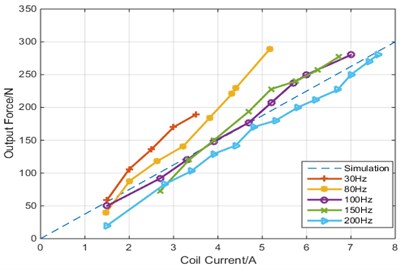
a) Output force characteristic of different coil current
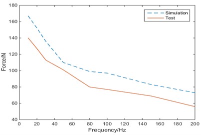
b) Output force characteristic of different frequency
4.2. Multi-channel vibration absorption control with fixed frequency excitation
The experiment bench and installation of vibration absorbers are as shown in Fig. 10.
The sinusoidal signal send out by signal generator is seemed as the initial vibration, with frequency of 37 Hz and amplitude of 2. Nest the experimental plan is designed to verify the validity of the multi-channel control algorithm. The details are as follows: No. 1 and No. 2 vibration absorbers used as passive vibration absorber are installed in the experiment bench without active vibration absorber, as shown in Fig. 10. Error vibration signal collected by error sensor is seemed as the vibration evaluation index. Because the fixed structure of passive absorbers is different from that of active absorbers, No. 1 and No. 2 passive absorbers are replace by active vibration absorbers in the diagonal position. White noise sent out by controller is used to identify the model of secondary path, the order of FIR is 500. Identification of secondary path are fed back to the control system to carry out the adaptive vibration absorption experiment, in which, the orders of two control filter are 128 and the initial value is zero. Identification of secondary path are as shown in Fig. 11.
Error vibration signals before and after control collected by error sensors are shown in Fig. 12.
Fig. 10Experiment bench and installation of vibration absorbers
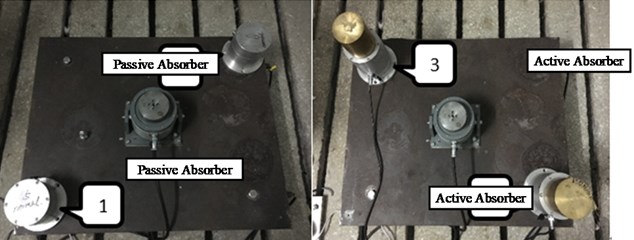
In Fig. 12, the absorption effect is not obvious when the 1 and 2 passive vibration absorbers are used in control system, because the excitation frequency is far from resonant frequency. While the 3 and 4 electromagnetic active vibration absorbers are totally different, the absorption effect is obvious. The output force can be changed to the excitation signal adaptively, ignoring the difference between excitation frequency and resonant frequency. The details of damping effect are as shown in Table 2.
Fig. 11Identification of secondary path
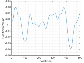
a) Identification of
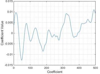
b) Identification of
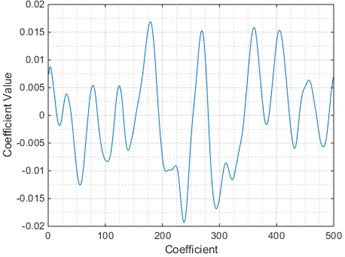
c) Identification of
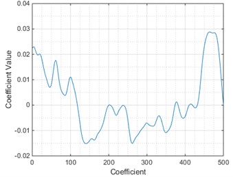
d) Identification of
Fig. 12Error signals and spectrum before and after control
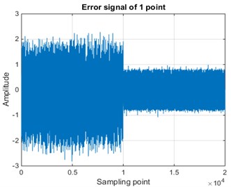
a) Error signal of 1 point
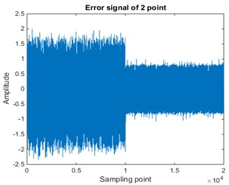
b) Error signal of 2 point
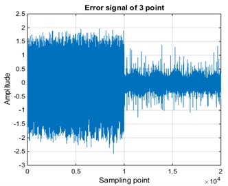
c) Error signal of 3 point
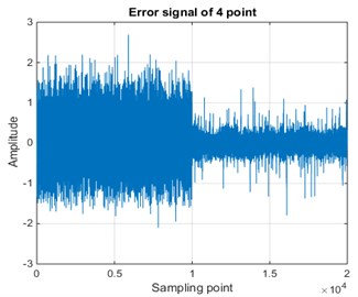
d) Error signal of 4 point
The phase-space reconstruction is used in the analysis of error vibration signals, the attractor has obviously changed after control, as shown in Fig. 13. The change of attractor indicates the validity of multi-channel control algorithm, and also indicates the error influence of nonlinear in the multi-channel control system. because the attractor does not have the characteristics of limit cycle. So, in the nest optimization algorithms, the nonlinear influence needs to be further compensated.
Table 2Damping effect of each vibration absorber
Vibration absorber | No control (spectrum) | Control (spectrum) | Noise reduction performance |
1 | 0.7545 | 0.5601 | 2.6 (dB) |
2 | 0.7602 | 0.5705 | 2.5 (dB) |
3 | 0.7563 | 0.1771 | 12.6 (dB) |
4 | 0.7846 | 0.1435 | 14.8 (dB) |
Fig. 13Phase-space reconstruction of error signals before and after control
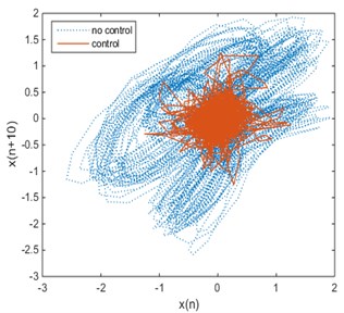
a) Phase-space reconstruction of 3 error signal
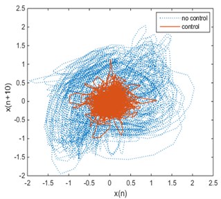
b) Phase-space reconstruction of 4 error signal
5. Conclusions
In the distributed multi-channel adaptive vibration absorption control system with electromagnetic active vibration absorber, the key lies in the nonlinear compensation for the active vibration absorption and the influence of coupling between channels. A New type electromagnetic active vibration absorber and distributed multi-channel adaptive control algorithm are designed to solve the above problems. The conclusions are as follows:
1) The electromagnetic active vibration absorber designed in this article can provide electromagnetic force in both directions through the electromagnets in upper and lower of soft iron, without applying the bias current. The relationship between input current and output force can be approximately linear. The nonlinear influence on control is reduced significantly.
2) In the distributed multi-channel adaptive control algorithm system, the first step is to identify the secondary path. And then, coupling between channels can be compensated on each control loop through matrix approximation. Each control loop can be seemed as basically independent. This algorithm improves the stability of control system and reduces the calculation at the same time.
3) The traditional passive vibration absorber is limited to the resonant frequency of vibration absorber itself, and it means that the effect is not obvious when the excitation frequency is far away from resonant frequency. The output force of active vibration absorber can adjust to the excitation current adaptively, ignoring the difference between excitation frequency and resonant frequency. The absorption range is expanded, and the damping effect of electromagnetic active vibration absorber is obvious, which can reach 15 dB.
The attractor of phase-space reconstruction indicates the error influence of nonlinear in the control system, because the attractor does not have the characteristics of limit cycle. So, in the optimization algorithm, the nonlinear influence needs to be further compensated.
1) The magnetic circuit structure of electromagnetic active vibration absorber can be further optimized to reduce the nonlinear influence.
2) Application of Neural network in identification of secondary path can reduce the nonlinear error between simulation model and actual transfer function.
3) The output of electromagnetic absorbers may make great influence on the collection of reference signal, this need to be considered in the actual control system.
References
-
Trumper D. L., Olson S. M., Suberahmanyan P. K. Linearizing control of magnetic suspension system. IEEE Transactions on Control System Technology, Vol. 5, Issue 5, 1977, p. 427-438.
-
Lindlau J., Knospe C. Feedback linearization of an active magnetic bearing with voltage control. IEEE Transactions on Control System Technology, Vol. 10, Issue 1, 2002, p. 21-31.
-
Jiang Weikang, Wang Quan, Yan Li, et al. Constrained damping dynamic absorber stuck on a rail of urban transits. Journal of Vibration Engineering, Vol. 12, Issue 4, 1999, p. 584-589, (in Chinese).
-
Chung Jintai Vibration absorber for reduction of the in-plane vibration in an optical disk drive. IEEE Transactions on Consumer Electronics, Vol. 50, Issue 2, 2004, p. 552-557.
-
Wu Chongjian, Ruo Dongping, Yang Shuzi, et al. Design and application of multiple tuned mass damper for ships. Journal of Vibration Engineering, Vol. 12, Issue 4, 1999, p. 584-589, (in Chinese).
-
Wu Tianxing On the railway track dynamics with rail vibration absorber for noise reduction. Journal of Sound and Vibration, Vol. 309, Issues 3-5, 2008, p. 739-755.
-
Sun H. L., Zhang P. Q., Gong X. L., et al. A novel kind of active resonator absorber and the simulation on its control effect. Journal of Sound and Vibration, Vol. 300, Issues 1-2, 2007, p. 117-125.
-
Ren Bolin, Liu Lilan, Zhang Xiaojing, et al. Dynamic characteristics and parametric influences of nonlinear vibration absorbers based on bi-stable power generation. Journal of Vibration and Shock, Vol. 36, Issue 17, 2017, p. 220-230, (in Chinese).
-
Yang Fei, Yang Zhichun, Wang Wei Frequency design of dynamic vibration absorber for flutter suppression of a sandwich panel. Journal of Vibration and Shock, Vol. 28, Issue 7, 2009, p. 65-68, (in Chinese).
-
Sun Hongling, Zhang Kun, Zhang Pengqiang, et al. Application of dynamic vibration absorbers in floating raft system. Applied Acoustics, Vol. 71, Issue 3, 2010, p. 250-257.
-
Zhou D., Debrunner V. Efficient adaptive nonlinear filters for nonlinear active noise control. IEEE Transactions on Circuits and System I: Regular Papers, Vol. 54, Issue 3, 2007, p. 669-681.
-
Sayed M., Kamel M. 1:2 and 1:3 internal resonance active absorber for non-linear vibrating system. Applied Mathematical Modelling, Vol. 36, Issue 1, 2012, p. 310-332.
-
Yong Chen, Zimcik David G., Wickramasinghe Viresh K., Nitzsche Fred Research of an active tunable vibration absorber for helicopter vibration control. Chinese Journal of Aeronautics, Vol. 16, Issue 4, 2003, p. 203-211, (in Chinese).
-
Alision Flatau B., Marcelo Dapino J., Frederick Calkins T. High bandwidth tunability in a smart vibration absorber. Journal of Intelligent Material System and Structures, Vol. 24, Issue 18, 2013, p. 923-929.
-
Li Zhongjie, Zuo Lei, Luhrs George, Lin Liangjun, Qin Yixian Electromagnetic energy-harvesting shock absorber: design, modeling, and road tests. IEEE Transactions on Vehicular technology, Vol. 62, Issue 3, 2013, p. 1065-1075.
-
Yan Bo, Zhong Xinong, Niu Hongpan Vibration isolation of a beam via negative resistance electromagnetic shunt dampers. Journal of Intelligent Material System and Structures, Vol. 23, Issue 6, 2012, p. 665-673.
-
Steen Krenk, Jan Hogsberg Tuned mass absorbers on damped structures under random load. Probabilistic Engineering Mechanics, Vol. 23, 2008, p. 408-415.
-
Deng Huaxia, Gong Xinglong Adaptive tuned vibration absorber based on magnetorheological elastomer. Journal of Intelligent Material Systems and Structures, Vol. 18, Issue 12, 2007, p. 1205-1210.
-
Kela L., Vahaoja P. Recent studies of adaptive tuned vibration absorbers/neutralizers. Applied Mechanics Review, Vol. 62, Issue 6, 2009, p. 060801.
-
Wen Yongpeng, Li Qiong, Shang Huilin, Xu Xiaojun Performances of dynamic absorbers for urban rail vehicle body considering effects of vehicle-track coupling. Journal of Vibration and Shock, Vol. 35, Issue 21, 2016, p. 53-62.
-
Lu Zeqi, Yang Tiejun, Chen Liqun, Brennan Michael J., Liu Zhigang Dynamic behavior and optimization of a nonlinear vibration absorber. Journal of Vibration Engineering, Vol. 29, Issue 5, 2016, p. 765-771.
-
Luo Lei, Sun Jinwei, Huang Boyan A novel feedback active noise control for broadband chaotic noise and random noise. Applied Acoustics, Vol. 116, 2017, p. 229-237, (in Chinese).
About this article

The research leading to these results has received funding from the National Natural Science foundation of China (NSFC) under the grants No. 51579242, No. 51509253 and No. 51679245. All the supports mentioned above are gratefully acknowledged.
