Abstract
In this paper, the studies on an influence of the parameters of the loading heads on the stability and free vibrations as well as on loading capacity of the cracked column subjected to a specific load are presented. The defect of the host structure has a form of a crack and is simulated by means of the rotational spring. The boundary problem is formulated by use of Hamilton’s principle on the basis of which the differential equations of motion as well as natural boundary conditions are obtained. The main scope of this study is to estimate an influence of the parameters of the loading heads on stability and free vibrations as well as on loading capacity of the cracked column. Finally, the numerical simulations are compared to the experimental ones.
1. Introduction
In the scientific books and papers, one can find many studies which were dedicated to the slender structures in the form of columns. The presented systems were subjected to the different types of external and/or internal loads. The most popular one is the load introduced into mechanics by the Euler – load with a constant line of action [1-3]. Euler’s load load as well as the generalized load [4-6] and the specific load [7-9] are known as conservative ones. Non-conservative loads such as: Beck’s load, the generalized Beck’s load, Reut’s load and the generalized Reut’s load [10-13] are the separate group. The specific load, considered in this paper, was introduced into literature by L. Tomski [7]. The load can be realized by means of the loading heads with the outline in the shape of: circular elements [6, 14, 15], parabolic elements [16] or linear elements [7, 16]. The specific load can be induced by the generalized load with a force directed towards a negative or positive pole [7] or by a follower force directed towards a negative or positive pole [6]. The pole is a point located below the loaded end of the column on its undeformed axis. The connection of the pole point and the loaded end of the column creates a line of action of an external load.
In the produced, installed and used structures or devices, the appearance of the crack is highly undesirable. The crack presence affects not only visual aspects but moreover changes the static and dynamic parameters of the object that can significantly differ from the designed ones. Regardless of the discussed object, the crack growth finally leads to great damage or total destruction which creates very dangerous phenomena in some specific situations. Early identification of a crack and the repair or improvement of the structure is a basic task for engineers. In scientific literature, cracks are divided into two types. Depending on the type of the investigated problem, the linear simulations can be computed in which the crack remains always open or the non-linear ones can be studied where the crack opens and closes in time.
Based on the analysis of the mathematical models proposed in the literature, the cracks can be simulated as a reduced cross-section area, complex mathematical functions or rotational springs. As shown by Chondros [17] and Arif Gurel [18], the rotational springs can be used as elements that simulate cracks despite their simplicity. Authors have shown that the results obtained during experiments and numerical simulations have great convergence. Ostachowicz and Krawczuk [19] have presented the method of estimation of the rotational spring stiffness on the basis of the crack parameters. Sokół [20, 21] used rotational springs in the studies on the crack presence in the multi-member columns. The presented results allowed one find the crack on the basis of the analysis of the characteristic curves, vibration and buckling modes, amplitude – vibration frequency relationship. The rotational springs were also used in the studies carried out by Binici [22] where the multi-cracked beams were considered. Dimarogonas et. al. [23, 24] proposed the use of the flexibility matrix and Rayleigh principle in the studies on the change of natural vibration modes and frequency changes as a result of the crack presence. Kukla [25] has used rotational springs in the studies on the cracked column with a stepped cross-section area.
In the scientific manuscripts, a reduction of the loading capacity of the system due to crack presence is mostly presented. The external loads are restricted to Euler’s load. In this study the specific load is introduced as a load of a cracked supporting system. The main scope of this study is to find such a combination of the parameters of the loading heads at which an influence of the crack presence on loading capacity, free vibrations and vibration modes will be reduced.
2. The boundary problem formulation
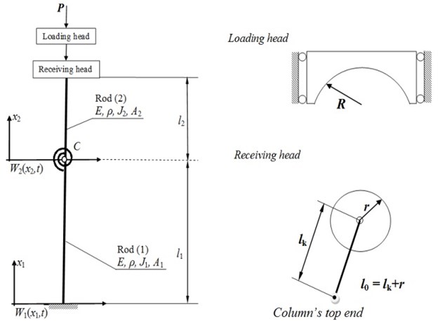
In Fig. 1, the investigated damaged column is presented. The external load is realized with the use of the loading heads with circular outlines. The defect of the column has a form of a one-sided open crack that divides a system into two elements. The crack in this study is simulated by means of the rotational spring of stiffness . Spring stiffness can be calculated with consideration of the studies done by Ostachowich and Krawczuk [19]. In the point of the crack presence, the continuity of transversal and longitudinal displacements as well as bending moments and deflection angles are satisfied by natural boundary conditions. As the crack divides the column into two elements, the total length of the structure is expressed as . Additionally, the mass is placed on the loaded end which allows one to simulate the mass of the loading heads. In the specific load, two loading heads are present. The first one of radius is mounted on the bearings which guarantees smooth motion of the head in the vertical direction; radius has a center in the pole point placed below the loaded end of the column on its undeformed axis. The line of action of force passes through the pole. The second head has radius and is a load receiving head. The distance between the end of the column and the contact point of both heads is – transom length.
The mathematical model is created on the basis of the following assumptions: the material of the host structure is homogeneous, the column has a rectilinear form of static equilibrium, the column is classified as a slender system that allows one to use the Bernoulli-Euler theory [26], the construction of heads generates the generalized load with a force directed towards a positive pole. The boundary problem has been formulated on the basis of Hamilton’s principle:
According to which the kinetic and potential energies are described as follows:
here:
The designations in Eqs. (2-5) are as follows: – Young’s modulus [GPa], – moment of inertia [m4], – cross-sectional area [m2], – material density [kg/m3], – rotational spring stiffness [Nm], – external load [N], – transversal displacement [m], – radius of the loading head [m], – radius of the load receiving head [m], – mass of heads [kg], – transom length [m].
Fig. 1The investigated system
After performing variation and integration operations, one obtains equations of motion:
The investigated structure can be described by the following geometrical boundary conditions in the form:
The natural boundary conditions are obtained from the variational formula with the use of geometrical boundary conditions Eq. (7) and take a form:
The further investigations are done in the non-dimensional form, where:
which, after separation of time and space variables, allows one to write the differential equation of motion in a transversal direction in a form:
The general solution of Eq. (10) is taken as follows:
where:
Substitution of Eq. (11) into boundary conditions leads to the system of homogenous equations with unknowns , , , ( 1, 2). When the matrix determinant is equated to zero, one obtains the transcendental equation on the basis of which the vibration frequency at the rectilinear form of static equilibrium is found.
3. The results of numerical simulations
The results of numerical simulations are divided into three sections and are presented in the non-dimensional form. In each of the results, an influence of one parameter (, , ) is discussed. Additionally, in all presented figures: the crack is placed in the middle of the total length of the column – 0.5; bending rigidity relationship is equal to 1. The investigated ranges of , , are determined on the basis of the real life structure. The non-dimensional parameters are as follows:
The non-dimensional parameters , , describe the relation between radiuses of heads in relation to the transom and column length.
3.1. An influence of
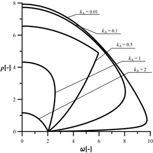
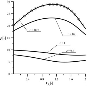
The investigated range of is . In the Figs. 2-5 an influence of the radius on the stability and vibrations of the column at different crack sizes is presented. Curves plotted in Fig. 2 can be treated as a reference ones (uncracked column – high stiffness of the rotational spring). In this case, an increase in results in reduction of the maximum loading capacity of the column. It must be stated that the investigated system is characterized by two shapes of characteristic curves.
Fig. 2An influence of the kA parameter on the shape of the characteristic curves, c= 106, kB= 0.2, kC= 0.5, d2= 0.5, μ= 1
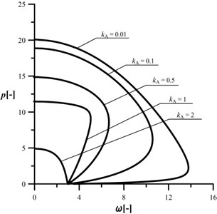
Fig. 3An influence of the kA parameter on the shape of the characteristic curves, c= 10, kB= 0.2, kC= 0.5, d2= 0.5, μ= 1
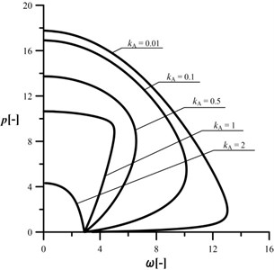
The first one (divergence – pseudoflutter) is present at such ,when the magnitude of the vibration frequency is increasing along with external load and, after reaching the maximum point, the vibration frequency is decreasing up to the point of instability ( 0). The second type is a classic divergence instability at 2. The presence of the crack (Figs. 3-5) results in reduction in the vibration frequency and loading capacity in relation to the reference system. The most important conclusion is that the loading capacity of the cracked system can be controlled by the proper selection of the radius of the loading head. The control of change in the vibration frequency can be done at divergence-pseudoflutter instability. In the case of the divergence instability, an increase in the magnitude of the parameter always causes reduction of the loading capacity and an increase in the negative slope of the characteristic curve.
The size of the reduction of the vibration frequency is relatively small when compared to the reduction of the loading capacity. An analysis of the characteristic curves allows one to also state that an increase in parameter (0.01 to 0.1) results in a “shift” of the curves to the location in which they are overlapping each other (Figs. 4 and 5). Furthermore, at “big” cracks, the characteristic curves can be “sharp” pointed (Fig. 5, 0.5). The combination of the crack located in the middle of the column and 0.5 (the radius of the loading head is equal to half of the length of the column) results in the rapid change of the shape of the characteristic curve (sharp point). In this case, the change in vibration mode is also rapid.
Fig. 4An influence of the kA parameter on the shape of the characteristic curves, c= 1, kB= 0.2, kC= 0.5, d2= 0.5, μ= 1
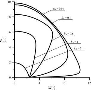
Fig. 5An influence of the kA parameter on the shape of the characteristic curves, c= 0.5, kB= 0.2, kC= 0.5, d2= 0.5, μ= 1
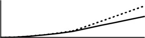
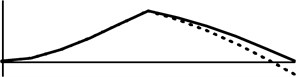
The results of supplementary studies on vibration modes are presented in the figs. below. The dotted line corresponds to 0.5, while the continuous one stands for 0.1.
Fig. 6Shape modes at different kA
a) 1, 0.2, 0.5, 0.5, 0.5, 1
b) 1, 0.2, 0.5, 8, 0.5, 1
The studies on vibration modes are done with normalization in the form 0.1. As shown in the Fig. 6, the vibration mode is changing along with an increasing external load magnitude. At the section of the characteristic curve with a positive slope, the first vibration mode can be observed, while at the negative one the first vibration mode changes into the second one. The change of vibration modes is specific to divergence – pseudoflutter systems (in the divergence ones, vibration modes are constant). An increase in the parameter results in increase of the transversal displacements of the rods (especially the second one) which leads to the reduction of the maximum loading capacity. The presence of the crack can be easily detected after the analysis of the vibration modes (the point of discontinuity of the first derivative). The change of the vibration modes as shown above can also be found at other magnitudes of , and .
In the Figs. 7 and 8, an influence of the parameter on the loading capacity of the column has been presented at different crack sizes. The mathematical model, proposed in this paper, can be verified by a comparison of the results at high spring stiffness with the ones published by Tomski [15] (circle symbols). In Fig. 7, at very small radius of the loading head, the loading capacity of the column is the highest at every considered . An increase in causes the maximum external load magnitude reduction irrespectively to the crack. At higher (Fig. 8) the change of the loading capacity is totally different. An increase in parameter results in an initial increase in the loading capacity and finally a decrease in the critical load can be observed for small cracks. When spring stiffness is lower than 5, the change of parameter causes an initial drop of the critical load magnitude up to the minimum (which depends on the crack size). A further increase in leads to the small increase in the loading capacity of the column. The control of parameter allows one to achieve the control of the loading capacity regardless of the crack size.
Fig. 7An influence of the kA parameter on the maximum loading at different c, kB= 0.2, kC= 0.5, d2= 0.5, μ= 1
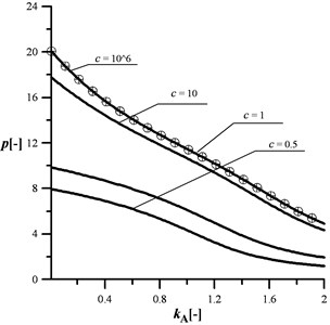
Fig. 8An influence of the kA parameter on the maximum loading at different c, kB= 0.8, kC= 0.5, d2= 0.5, μ= 1
3.2. An influence of on the shape of the characteristic curves
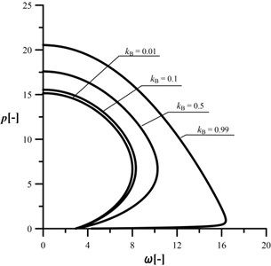
The investigated range of is set to . The Figs. 9-12 contain the curves that show an influence of the radius in relation to on the stability and vibrations of the column at different crack sizes. Data plotted in Fig. 9 are treated as data obtained for a reference system (uncracked). In this case an increase in results in increase in the maximum loading capacity of the column. In the studies into an influence of parameter on the stability, only the divergence-pseudoflutter instability has been obtained. The presence of crack (Figs. 10-12) results in reduction of the vibration frequency and loading capacity in relation to the reference system. As presented, the loading capacity of the cracked system can be still controlled by the proper selection of the relation between radiuses and of the heads. The size of control is decreasing along with reduction in the stiffness of the rotational spring. The greater the crack, the smaller influence of the parameter on the critical load magnitude. Reduction of the spring stiffness also causes the “shift” of the characteristic curves to the location in which they are partially overlapping each other. Based on the presented results, it can be concluded that curves overlapping will be greater at lower spring stiffness.
Fig. 9An influence of the kB parameter on the shape of the characteristic curves, c= 106, kA= 0.2, kC= 0.5, d2= 0.5, μ= 1

Fig. 10An influence of the kB parameter on the shape of the characteristic curves, c= 10, kA= 0.2, kC= 0.5, d2= 0.5, μ= 1
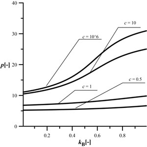
The results of an influence of the on the loading capacity are plotted in Figs. 13 and 14. When the magnitude of is 0.2, an increasing results in increase in the loading capacity at cracks 5. At greater considered cracks, the change in the maximum external load is very small. At a much higher (Fig. 14), the shape of the obtained curves is more interesting. An increase in causes an increase in the loading capacity of the column which highly depends on the crack size – the smaller crack the more rapid the increase in the maximum external load magnitude.
Fig. 11An influence of the kB parameter on the shape of the characteristic curves, c= 1, kA= 0.2, kC= 0.5, d2= 0.5, μ= 1
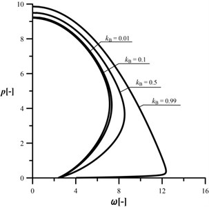
Fig. 12An influence of the kB parameter on the shape of the characteristic curves, c= 0.5, kA= 0.2, kC= 0.5, d2= 0.5, μ= 1
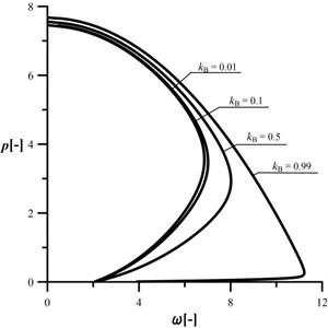
Fig. 13An influence of the kB parameter on the maximum loading at different c, kA= 0.2, kC= 0.5, d2= 0.5, μ= 1
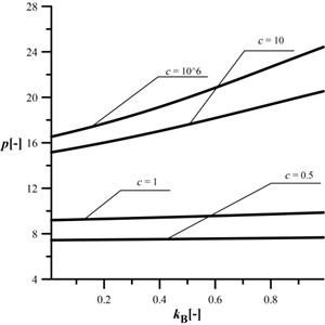
Fig. 14An influence of the kB parameter on the maximum loading at different c, kA= 0.8, kC= 0.5, d2= 0.5, μ= 1
3.3. An influence of on the shape of the characteristic curves
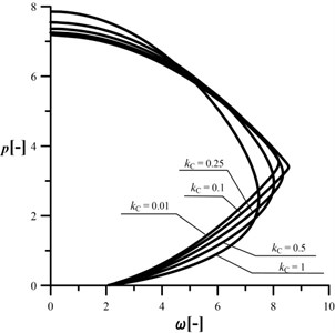
The investigated range of is . In Figs. 15-18 the results of studies on an influence of the transom length in relation to radius on the stability and vibrations of the column at different crack sizes are plotted. Data included in Fig. 15 are computed for a reference structure – uncracked column. In this case, an increase in results in a decrease in the maximum loading capacity of the column. At every considered parameter magnitude, the divergence–pseudoflutter instability has been obtained. The presence of crack (Figs. 16-18) results in reduction in the vibration frequency and loading capacity in relation to the reference system. The loading capacity of the damaged system can be controlled by the proper selection of the transom length . Generally, the shorter the transom the higher loading capacity. The size of the control of the investigated parameters is decreasing along with an increase in the crack size – the greater the crack the smaller influence of the parameter. At 1 (Fig. 18) an increase in the parameter causes an increase in the maximum external load (unlike the small cracks). Despite that, the loading capacity is the lowest.
Fig. 15An influence of the kC parameter on the shape of the characteristic curves, c= 106, kA= 0.2, kB= 0.5, d2= 0.5, μ= 1
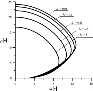
Fig. 16An influence of the kC parameter on the shape of the characteristic curves, c= 10, kA= 0.2, kB= 0.5, d2= 0.5, μ= 1
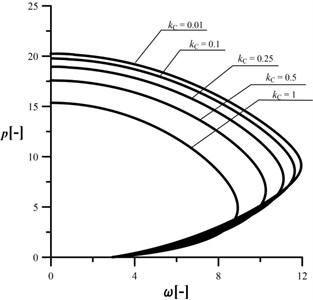
Fig. 17An influence of the kC parameter on the shape of the characteristic curves, c= 1, kA= 0.2, kB= 0.5, d2= 0.5, μ= 1
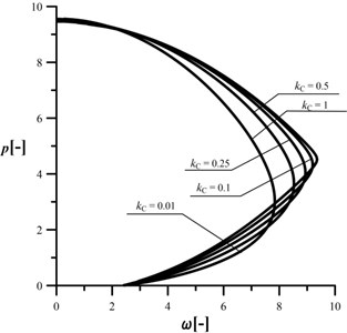
Fig. 18An influence of the kC parameter on the shape of the characteristic curves, c= 0.5, kA= 0.2, kB= 0.5, d2= 0.5, μ= 1
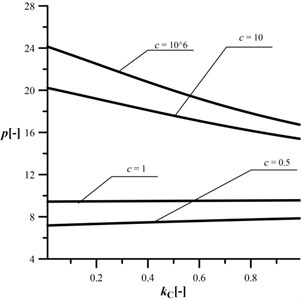
In Fig. 19, an influence of the parameter on critical load magnitude has been plotted. The change in results in a decrease in the loading capacity at small cracks and a very low increase at great cracks. The size of the reduction of maximum external load magnitude is much greater than an increase.
Fig. 19An Influence of the kC parameter on the maximum loading at different c, kA= 0.2, kB= 0.5, d2= 0.5, μ= 1
4. Experimental verification
The experimental studies were performed on the stand designed for slender structures. The photos of the stand and loading heads can be found in Fig. 20.
Fig. 20Experimental stand
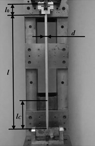
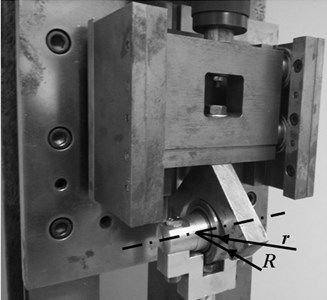
In the studies, the accelerometer Bruel&Kjaer 4508B, the analyzer Bruel&Kjaer 3560C and the PC unit with PULSE software were used. The dimensions of the test sample are as follows: 0.683 [m], 0.015 [m] and it is made of aluminum ( 7.5×10¹⁰[Pa]). The crack is located at 0.17 [m] from the fixed end and has a height of 0.002 [m] and depth of 0.004 [m]. The parameters of the loading structures are as follows: 0.04 [m], 0.0275 [m], 0.083 [m]. A test column was firstly installed at the test stand in such a way that one end was fixed while the load receiving head was mounted to the other. At given magnitude of externa load (realized by the servo-motor), the column was excited with an exciter. After that, the measurement of the acceleration was done at given external load. The signal from the analyzer unit was transmitted to the PULSE software which allows one to obtain the magnitude of the vibration frequency. The studies were performed at a rectilinear form of static equilibrium. Analogous studies were done at undamaged and damaged samples.
Fig. 21Theory vs. experiment – uncracked system (c= 106)
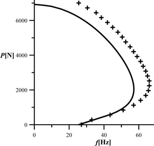
Fig. 22Theory vs. experiment – cracked system (c≈ 10)
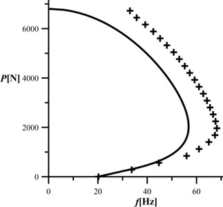
The results of the studies are presented in Figs. 21 and 22. The continuous line corresponds to the numerical studies while cross-marks correspond to the experimental ones. The presented data are obtained as an average of the three measurements . It can be concluded that the good accuracy of the results has been obtained especially at low magnitude of the external load. Furthermore, the shape of the characteristic curve (divergence – pseudoflutter curve) of the cracked and uncracked systems was confirmed in the experimental studies. The percentage error of the proposed mathematical model can be calculated as (th- theory). The smallest differences can be found at small magnitude of the external load; with an increasing load the differences are becoming greater ( 560 N – err. 1,21 %, 1400 N – err. 9,18 %, 3920 N – err. 15,88 %, 6160 N – err. 32,46 %). The error between the theoretical analysis and experiment is increasing at greater magnitude due to simplifications of the mathematical model (no strain in the contact patch, infinite stiffness of the fixed support) and inaccuracy of accelerometer installation.
5. Conclusions
In this paper, the investigations into the loading capacity and vibration frequency of a cracked column subjected to the specific load realized by circular elements of heads were presented. The crack was modeled as a rotational spring of stiffness . The main scope of the study was to estimate the possibility of finding such parameters of the loading heads at which the system will be less sensitive to the crack presence. Additionally, the proposed mathematical model was validated in the experimental studies. Summarizing the results, it can be concluded that:
– the proper selection of the parameters of the loading heads allows one to control the shape of the characteristic curves irrespectively of the crack size,
– the area of control depends not only on parameter of the loading heads but also on other parameters such as the crack size and location or bending rigidity ratio,
– the parameters of the heads allow one to control the type of instability,
– an unwanted effect of the crack presence can be reduced by the change of the parameters of the loading heads.
The differences in the obtained results from the experimental and numerical studies can be caused inter alia by: not considering the strain of the contact patch in the mathematical model, inaccuracy of calculation of material properties, inaccuracy of accelerometer installation, taking into account the mathematical infinite stiffness of the fixed support. The presented results can be applied during the design of the slender supporting structures in which defect in the form of a crack in the host element may appear.
References
-
Leipholz H. H. E. On conservative elastic systems of the first and second kind. Ingenieur Archiv, Vol. 43, 1974, p. 255-271.
-
Tomski L. Prebuckling behaviour of compound column – direct nonlinear analysis. Journal of Applied Mathematics and Mechanics, Vol. 65, Issue 1, 1985, p. 59-61.
-
Tomski L., Szmidla J. Local and global instability and vibration of overbraced Euler’s column. Journal of Theoretical and Applied Mechanics, Vol. 41, Issue 1, 2003, p. 137-154.
-
Gajewski A., Życzkowski M. Optimal shaping of an elastic homogeneous bar compresed by polar force. Biulletyn de L’Academie Polonaise des Sciences, Vol. 17, Issue 13, 1969, p. 479-488.
-
Gajewski A., Życzkowski M. Optimal shaping of a compressed rod by a force towards a pole. Rozprawy Inżynierskie, Vol. 2, Issue 17, 1969, p. 299-329, (in Polish).
-
Tomski L., Przybylski J., Gołębiowska Rozanow M., Szmidla J. Vibration and stability of a cantilever column subject to a follower force passing through a fixed point. Journal of Sound and Vibration, Vol. 21, Issue 1, 1998, p. 67-81.
-
Tomski L., Gołębiowska Rozanow M., Szmidla J. Free vibration of a column loaded by a force and bending moment. Vibrations in Physical Systems, Vol. 16, 1994, p. 317-319.
-
Tomski L., Uzny S. Vibration and stability of geometrically non-linear column subjected to generalized load by a force directed towards the positive pole. International Journal of Structural Stability and Dynamics, Vol. 8, Issue 1, 2008, p. 1-24.
-
Tomski L., Uzny S. Chosen slender systems in aspect of possibility of specific load realization. Journal of Sound and Vibrations in Physical Systems. Vol. 24, 2010, p. 429-434.
-
Beck M. Stability of one-sided clamped tangentially compressed rod. Journal of Applied Mathematics and Physics (ZAMP), Vol. 3, Issue 4, 1952, p. 225-228, (in German).
-
Langthjem M. A., Sugiyama Y. Dynamic stability of columns subjected to follower loads: a survey. Journal of Sound and Vibration, Vol. 238, Issue 6, 2000, p. 809-851.
-
Nemat Nasser S., Herrmann G. Adjoint systems in nonconservative problems of elastic stability. American Institute of Aeronautics and Astronautics, Vol. 4, Issue 15, 1966, p. 2221-2222.
-
Tomski L., Uzny S. The regions of flutter and divergence instability of a column subjected to Beck’s generalized load taking into account the torsional flexibility of the loaded end of the column. Research Mechanics Communications, Vol. 38, 2011, p. 95-100.
-
Tomski L., Szmidl, J. Vibration and stability of column subjected to generalized load by a force directed towards a pole. Journal of Theoretical and Applied Mechanics, Vol. 42, Issue 1, 2004, p. 163-193.
-
Tomski L., Uzny S. Vibrations and stability of a column subjected to the specific load realized by circular elements of heads. Mechanics and Mechanical Engineering, Vol. 17, Issue 2, 2013, p. 197-206.
-
Tomski L., Uzny S. The new realization of the specific load – free vibrations of a column. Dynamical Systems, Analytical/Numerical Methods, Stability, Bifurcation and Chaos, Łódź, 2011, p. 301-306.
-
Chondros T. G., Dimarogonas A., Yao J. A continuous cracked beam vibration theory. Journal of Sound and Vibration, Vol. 215, 1998, p. 17-34.
-
Arif Gurel M. Buckling of slender prismatic circular columns weakened by multiple edge cracks. Acta Mechanica, Vol. 188, 2007, p. 1-19.
-
Ostachowicz W. M., Krawczuk M. Analysis of the effect of cracks on the natural frequencies of a cantilever beam. Journal of Sound and Vibration, Vol. 150, 1991, p. 191-201.
-
Sokół K. Linear and nonlinear vibrations of a column with an internal crack. Journal of Engineering Mechanics, Vol. 140, Issue 5, 2014, https://doi.org/10.1061/(ASCE)EM.1943-7889.0000719.
-
Sokół K., Uzny S. Instability and vibration of multi-member columns subjected to Euler’s load. Archive of Applied Mechanics, Vol. 86, Issue 5, 2016, p. 883-905.
-
Binici B. Vibration of beams with multiple open cracks subjected to axial force. Journal of Sound and Vibration, Vol. 287, 2005, p. 277-295.
-
Dimarogonas A., Anifantis N. Stability of columns with a single crack subjected to follower and axial loads. International Journal of Solids and Structures, Vol. 19, 1999, p. 281-291.
-
Dimarogonas A., Chondros T. G. Dynamic sensitivity of structures to cracks. Journal of Vibration, Acoustics, Stress and Reliability in Design, Vol. 111, 1981, p. 251-256.
-
Kukla S. Free vibrations and stability of stepped columns with cracks. Journal of Sound and Vibration, Vol. 319, Issues 3-5, 2009, p. 1301-1311.
-
Uzny S., Sokół K. The Bernoulli-Euler and Timoshenko theories in the context of research on the characteristic curves of column with different boundary conditions. AIP Conference Proceedings, Vol. 1648, 2015.
About this article

