Abstract
Large inertia load has been widely used in space driving mechanisms, but the research concerning theory is still an unexplored scientific field. Towards the problem of nonlinear disturbance in space driving mechanism with large inertia load, a 14-DOF (Degree of Freedom) nonlinear, time-varying, dynamic model of two-stage spur gear system was established, taking into consideration time-varying stiffness, backlash and transmission error. The dynamic response of the load, under large or small inertia was investigated, basing on the dynamic model. The results indicate that at starting, normal operation and braking, large inertia load system has obvious hysteresis, compared to small inertia. The factors that improve dynamic response speed under large inertia load were studied. The results indicate that improving the stiffness and damping of the output shaft and changing the material of second gear pair to titanium alloy are helpful in improving the dynamic response speed of the system. Some results enrich the research of two-stage spur gear nonlinear model and large inertia load, since they provide important reference for the actual design of the gear system.
1. Introduction
Gear is one of the most widely used key components in mechanical equipment. Gear systems are often used to decelerate, increase available torque and change the direction of energy transmission. With the widespread use of large inertia load in space drive mechanisms, new problems and challenges rise in terms of life, reliability and safety of spacecraft designing, which relate to this parameter.
At present, the study of gear systems needs to establish a nonlinear, time-varying dynamic model, including backlash, time-varying stiffness and transmission error. Litak et al. [1] studied the dynamic response of the torsional model of single stage gear system. The results indicated that the nonlinear dynamic response is affected by external excitation. Junguo Wang et al. [2] investigated the torsional vibration model of single stage spur gear transmission system and analyzed the influence of stiffness on the dynamic behavior of locomotive gear transmission system. Lassâad Walha et al. et al. [3] and Kamel Abboudi et al. [4] established a 12-DOF nonlinear dynamic model for two-stage gear systems, which only considered the gear system itself and did not take the effects of input and output into consideration. Kamel Abboudi et al. [4] conducted a research on wind turbine generator and established the nonlinear dynamic model of two-stage spur gear, with backlash and time-varying stiffness. Furthermore, authors considered and studied the influence of internal and external excitation on the system. However, the backlash of the model was fixed and the influence of the transmission error on the gear system was not taken into consideration. In order to improve the computational efficiency, the finite element model was used, to estimate the influence of the center distance on the time-varying meshing stiffness by Fernandez et al. [5]. However, the backlash and the meshing angle in the dynamic model similar to above were fixed. Chen Siyu et al. [6] proposed a nonlinear dynamic model with dynamic backlash, friction and time-varying stiffness and discussed the differences between constant backlash model and dynamic backlash model. According to the finite element contact mechanics theory’, Parker et al. [7, 8], Vimson et al. [9] and Fernandez et al. [10] established the finite element model of gear transmission. With the finite element analysis software, Wu et al. [11] and Hua et al. [12] created the dynamic meta-model of the gear transmission system.
The dynamic characteristics of a gear system are affected by many parameters and have always been the focus of nonlinear dynamics research. Shen et al. [13] used the incremental harmonic balance method (IHBM) to analyze the nonlinear dynamic model of single-degree-of-freedom spur gear with backlash, time-varying stiffness and static transmission error considered and adopted the numerical simulation method to investigate the chaotic response of the gear system. Qi Chen et al. [14] used the fractal theory to represent the backlash and analyzed the influence of the backlash on the dynamic characteristics of the gear system. Wang Guangjian et al. [15] studied the dynamic transmission error of eccentric spur gear, based on finite element method. The influence of gear speed and stiffness on the dynamic response of gear system was analyzed by means of bifurcation diagram, phase plane diagram, Poincaré, time domain response diagram and amplitude spectrum by Junguo Wang et al. [2]. Regarding the oil squeezing between teeth, the effects of periodic backlash on gear vibration were analyzed by Ernesto Rocca et al. [16]. Z. Rao et al. [17] studied the nonlinear torsional instability of a two-stage gear system with a flexible shaft. Karahman et al. [18] analyzed the coupling between time-varying stiffness, backlash and the bearing gap based on the nonlinear time-varying model. Al-shyyab et al. [19] used IHBM and numerical method to analyze the nonlinear vibration response and amplitude jump characteristic of 2-DOF nonlinear dynamic model respectively. Lingli Cui et al. [20, 21] studied the effect of an angle-changing crack on the gear dynamic response by introducing two affecting lines, the parabolic-affecting line (PA) and the straight-affecting line (SA).
The analysis of the dynamic characteristics of large inertia load, space drive mechanism is less widespread in theoretical research, which mainly adopts simulation technology for analysis and research. Basing on the influence of large reduction ratio, the dynamic characteristics of space manipulator were studied by Tianfu Yang et al. [22]. Unlike the characteristic of large inertia load was not analyzed. Zhigang Xu [23] proposed an equivalent simulation method of large inertia load that simulated the large inertia required by the space station manipulator. Furthermore, authors verified the effectiveness of the method, by numerical simulation under different working conditions. Chen Shiqi et al. [24] demonstrated the bending and torsional coupling nonlinear dynamic model of planetary gears with low speed and heavy load, and studied the influence of friction on the nonlinear dynamic characteristics of low-speed, heavy-load gear drive. In the process of acceleration and deceleration of the gear system, large inertia load would cause great vibration due to the load inertia, which makes the system have poor steady-state characteristics during the speed changing process. Therefore, seriously affects the service life of the drive mechanism and even leads to catastrophic accidents, due to decreased reliability. The space drive mechanism studied in this paper needs to start and stop frequently during the working process, and there is an obvious disturbance phenomenon when starting and stopping. Therefore, the influence of large inertia load on the system is analyzed emphatically. Ahmed Hammami et al. [25] developed a planetary gear torsional focus parameter model with dynamic recirculation and examined the nonlinear behavior under variable load conditions.
A nonlinear, time-varying dynamic model of 14-DOF and two-stage spur gears was demonstrated in this paper, to examine the time-varying and nonlinear disturbance problems caused by a large inertia load-space drive mechanism, considering simultaneously the backlash, time-varying stiffness, transmission error and other factors. The dynamic response of the gear system under different working conditions was investigated and the optimal design scheme was given. Some results of this paper contribute to the research of two-stage spur gear nonlinear model and large inertia load. Furthermore, they offer useful information towards the actual design of the gear system. The application of these findings is not limited at the field of aerospace, but also provides a certain reference value in other scientific fields, such as machine tools, wind power equipment and shipping.
2. Nonlinear time-varying dynamic model
2.1. Establishment of dynamic model
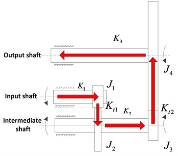
A dynamic modeling of a two-stage spur gear reduction system for a large inertia load space drive mechanism was developed under the following assumptions: the quality, the moment of inertia, the radius and the average meshing stiffness of each gear are evenly distributed along the center wheel. In addition, the system damping is elastic and the engaging force acts on the meshing surface and is perpendicular to the contact line of the tooth surface, ignoring the mutual sliding between the teeth. The two-stage spur gear transmission system was simplified as illustrated in Fig. 1, in which the power transmission process is indicated by the red arrow.
Fig. 1Transmission diagram of two-stage gear system
Using the concentrated mass method and ignoring the axial size, a nonlinear dynamic model of 14-DOF was established, as illustrated in Fig. 2. According to the dynamic model, the dynamic differential equations of the gear system can be represented as follows:
Fig. 2Dynamic model of two-stage gear transmission system
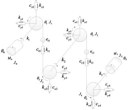
The symbols depicted in the Fig. 2 are: – the moment of inertia of the gears around the rotating shaft, 1, 2, 3, 4; , – the moment of inertia of the motor and load; , – motor input torque and the resistance torque of the load; – torsional stiffness of input shaft, intermediate shaft, output shaft, 1, 2, 3; – the damping coefficient of input shaft, countershaft and output shaft, 1, 2, 3; – the rotational angular displacement of input shaft, 4 gears and output shaft, 0, 1, 2, 3, 4, 5; – the radial stiffness of each bearing in the -axis direction, 1, 2, 3, 4; – the radial stiffness of each bearing in the -axis direction, 1, 2, 3, 4; – the radial damping coefficient of each bearing in the -axis direction, 1, 2, 3, 4; – the radial damping coefficient of each bearing in the -axis direction, 1, 2, 3, 4; – the time-varying meshing stiffness of gear pair , 1, 2; – the time-varying damping coefficient of gear pair , 1, 2; – the transmission error of gear pair , 1, 2.
Considering the time-varying meshing stiffness of the two-stage gear system, the radial displacement of the gears at the bearing, the tooth profile and the pitch error, according to Newton’s second law and related dynamics knowledge, the torsional vibration dynamics equations of two-stage spur gear are as follow:
where: – the gear quality of the two-stage gear system, 1, 2, 3, 4; – the base radius of each gear of the two-stage gear system, 1, 2, 3, 4; – the displacement of each gear in the -axis direction, 1, 2, 3, 4; – the displacement of each gear in the -axis direction, 1, 2, 3, 4.
2.2. Main non-linear factors
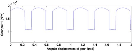
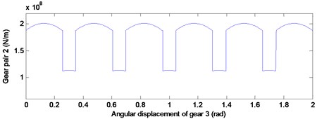
According to a previous study [2], the meshing stiffness of the gear system is approximately parabolic by changing of meshing position. For the determined by the parameter gear pair, the theoretical position of meshing in, meshing out and the joint are fixed. Thus, the time-varying stiffness curve of gear pair 1 and gear pair 2 were obtained by the undetermined coefficient method, as illustrated in Fig. 3. Then the time-varying stiffness data can be substituted into the dynamics model.
Fig. 3Time-varying stiffness curve of gear pair 1 and gear pair 2
a)
b)
Due to the existence of backlash, the two gears engaged with each other cannot always be engaged. Specifically, during the operation of starting procedure, the drive wheel must be rotated by the angle corresponding to the idle path, before engaging with the driven wheel and then the meshing stiffness appears. Therefore, it is necessary to modify the time-varying meshing stiffness in the dynamic equation. The modified time-varying meshing stiffness were:
where: , – actual meshing stiffness of gear pair 1 and gear pair 2; , – the backlash of gear pair 1 and gear pair 2.
Errors can inevitably occur in the production process and installation process of the gear system. Error excitation is an significant factor in the generation of vibration and noise. In this system, the tooth profile error and pitch error were considered in the form of a simple harmonic function, as follows:
where: , – profile error and pitch error, , , – amplitude coefficient of each order harmonic function of profile error, , , – amplitude coefficient of each order harmonic function of pitch error, – meshing angular displacement, – gear rotation angular displacement.
In summary, the gear transmission error can be expressed as:
2.3. Validness verification of model
To simplify the calculation, during solving the dynamic response of the two-stage gear transmission system, it is assumed that the radial stiffness and damping of four bearings are equal. Radial stiffness equals 6.56×10⁷ N/m and damping is 1.8×10⁵ N·s/m. The torsional stiffness of input shaft, intermediate shaft and output shaft torsional stiffness are respectively 1381.6 N·m/rad, 3555.446 N·m/rad and 4824.705 N·m/rad. Other related parameters of the gear system are presented in Table 1. The dynamic response of the gear system is solved by using the ode solver in MATLAB and the angular acceleration response curve of the output shaft is illustrated in Fig. 4(a).
Table 1Main parameters of gear transmission system
Name | Value | Name | Value |
Number of teeth of the first gear pair , | 18, 90 | The moment of inertia of gear 1 | 0.359×10⁻⁶ Kg·m2 |
Number of teeth of the second gear pair , | 18, 360 | The moment of inertia of gear 2 | 9.4365×10⁻⁷Kg·m2 |
The modulus of the first gear pair | 0.25 mm | The moment of inertia of gear 3 | 4.054×10⁻⁸ Kg·m2 |
The modulus of the second gear | 0.5 mm | The moment of inertia of gear 4 | 3.9047×10⁻³ Kg·m2 |
The moment of inertia of the load | 25.8 Kg·m2 | The moment of inertia of motor input | 0.000002 Kg·m2 |
According to Table 1, it is demonstrated that the number of the lower gear of first gear pair is 18, thus the angle between teeth equals 20°. Given the motor output angular velocity 6°/s, then the time interval of the first stage gear meshing was 20°/(6°/s) ≈ 3.33 s. By applying a similar methodology, the time interval of the second stage gear meshing was 16.67 s. , coincide with the meshing impact period in Fig. 4, verifying the accuracy of the dynamic model.
Fig. 4The angular acceleration response curve of the output shaft
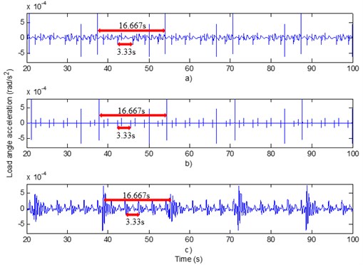
By removing the non-linear factors, such as profile error and pitch error in the dynamic model, the angular acceleration response curve of the output shaft is presented in Fig. 4(b). By comparison of Fig. 4(a) to Fig. 4(b), it is demonstrated that the dynamic response curve within non-linear factors fluctuates more frequently and the dynamic response curve without non-linear factors fluctuated only in the position of “meshing in and meshing out”. It is concluded that the nonlinear factors have a great influence on the dynamic response of the system. To ensure the accuracy of the dynamic model, the influence of the nonlinear factors must be taken into consideration.
To verify the validity of the dynamic model, a motion simulation experiment was performed in Adams. The simulation result is presented in Fig. 4(c). By comparison of Fig. 4(a) to Fig. 4(c), it is established that the dynamic response curves obtained by the two methods have good consistency. The validity of the dynamic model was proved by mutual verification of the two methods.
3. Comparison of dynamic response of load angular velocity under different inertia
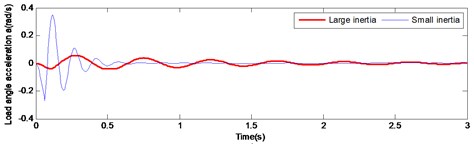
Considering the large inertia load in the dynamic model the drive mechanism was simulated. The input motor drive angular velocity was set 6°/s and a reverse resistance moment –1 N·m was added to the load side. The simulation duration was set to 80 s and the braking was set at 65 s. The blue line in Fig. 5 represents the simulation curve. To study the difference of the dynamic response of the drive mechanism under the large inertia and the small inertia load, the rotational inertia of the load was modified to simulate the dynamic response under the small inertia load. In current research, the load inertia was reduced to one-tenth of the initial case and the rest of the set conditions remained unchanged. The blue line in Fig. 5 represents the simulation result for the small inertia case. The dynamic response curve was divided into three parts of system startup, smooth working and system brake, as illustrated in Fig. 5.
Fig. 5Angular acceleration and angular velocity response curves of load under large and small inertia conditions
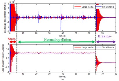
According to Fig. 5, the trend of system response is identical for both cases (large and small inertia). However, compared with the small inertia load system, the load angular velocity response of the drive mechanism under the large inertia load has significant hysteresis. This is due the delay effect of the large inertia load. To demonstrate more precisely the difference between the two systems (under large inertia and small inertia respectively), the system response at starting, normal operation and braking was partially amplified, as illustrated in Fig. 6, 7 and 8.
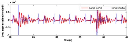
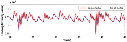
Initially, the load angular velocity and load angular acceleration were analyzed, in the drive mechanism, at normal operation and under different load inertia (Fig. 6). It was concluded that under large inertia, the overshoot the angular velocity and the angular acceleration of the system are lower compared to those under the small inertia in the meshing impact. However, the decay speed is significantly lower than that under the small inertia condition. This is caused by the large load inertia.
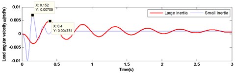
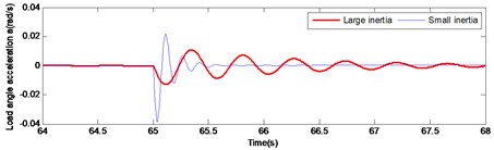
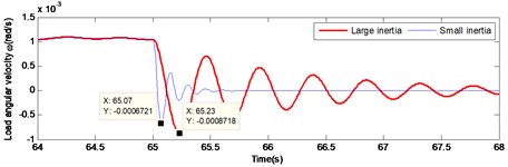
Fig. 7 and Fig. 8 illustrate the comparison of starting and braking load response curve respectively. It is pronounced that under large inertia, the load response is relatively slow, presenting a significant lag. In the start-up curve illustrated in Fig. 7, the load reaches the maximum speed at 0.152 s under the small inertia load, while the load reaches the maximum speed at 0.4 s under the large inertia. Thus, there is a lag of 0.248 s in time. In the braking curve presented in Fig. 8, the load reaches the maximum speed at 65.07 s under the small inertia load, while the load reaches the maximum speed at 65.23 s under the large inertia. Hence, a lag of 0.16 s occurs. Therefore, the lag of the large inertia load in time leads to a decreased accuracy system output. This has a direct negative effect on the stability of the gear system. Thus, maintenance life of the driving mechanism is seriously affected.
Fig. 6Comparison of large and small inertia load in angular velocity and angular acceleration during normal operation
a)
b)
Fig. 7Comparison of large and small inertia load in angular velocity and angular acceleration at start-up
a)
b)
Fig. 8Comparison of large and small inertia load in angular velocity and angular acceleration at braking
a)
b)
According to the previous analysis of the large and small inertia load drive mechanism, it was concluded that there is a significant difference in the load response of the same drive mechanism under two different inertia cases. The advantage of the large inertia load system is that the system has a smooth operation, as presented in Fig. 6, especially for the requirements of the high transmission accuracy. Due to the large inertia of the load, the system contributes in absorbing the disturbance during operation. The greater the inertia of the load is, the larger the anti-disturbance ability of the system becomes. Large inertia load also has some weakness. The running state of the gear system with a large inertia load has no mutation, thus the period to start or to brake will be long, as illustrated in Fig. 7 and Fig. 8.
As the inertia of the system increases, the greater the time constant of the system will be, the slower the response time will be and the worse the sensitivity will be. Thus, this will decrease the natural frequency of the system components, causing the system resonance. Therefore, the large inertia of the load affects the speed and accuracy of the system positioning, especially in the occasion of a fast and accurate positioning demand. The large inertia load leads to the slow response of the system, which inevitably has a significant effect in the motion error of the system. Therefore, it is of great importance to study the drive mechanism system under conditions of large inertia load.
4. Dynamic response of large inertia load system under different influencing factors
The nonlinear time-varying dynamic model of the driving mechanism was established in the first part of this paper. According to the dynamic model, it is concluded that the main parameters affecting the system response are the mass, stiffness and damping matrix of the system and additionally the external input excitation. The analysis of the large inertia load gear system was carried out towards stiffness and damping according to the following:
For the gear reduction system, the main stiffness components consist of the following three parts: a) the gear engagement stiffness and the stiffness of the input shaft, b) intermediate shaft and c) output shaft. At this part of the paper, the effects of the gear pair meshing stiffness and the stiffness of each axis under the large inertia load on the mechanism were investigated. For size-determined gear pair, the main parameter affecting the meshing stiffness is the teeth material and the stiffness of each axis can be modified by changing the material and size of the shaft.
4.1. Effect of the stiffness and damping of shaft on dynamic response
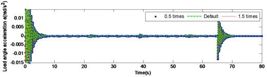
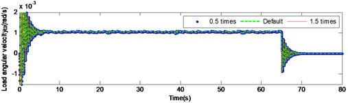
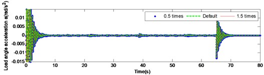
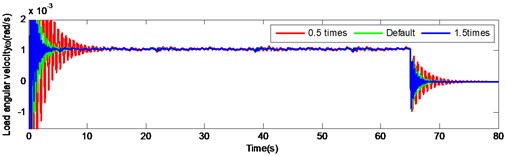
To investigate the influence of the three shafts on the dynamic response of the gear reduction system, the stiffness and damping of input shaft, intermediate shaft and output shaft were respectively modified at 0.5 and 1.5 times from the default value. By adopting this technique, the effect of the stiffness change on the dynamic response of the system by modifying the material or diameter of the shaft was simulated. The simulation results are illustrated in Fig. 9, 10 and 11.
Fig. 9 and Fig. 10 present the load angular velocity and angular acceleration curves by changing the torsional stiffness of the input and the intermediate shaft respectively under high inertia. It is pronounced, that changing the torsional stiffness of the input and the intermediate shaft has insignificant effect on the angular velocity and angular acceleration of the output.
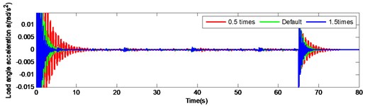
Fig. 11 illustrates the load response by changing the output shaft stiffness. According to the figure, changing the output shaft stiffness has a significant influence on the system and the attenuation is significantly accelerated by increasing the stiffness.
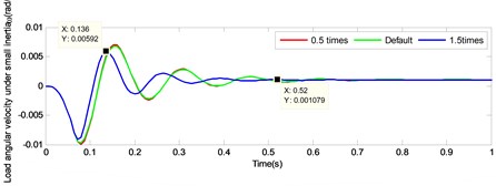
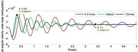
To study the difference between the large and the small inertia by changing the output shaft stiffness, the load response by changing the stiffness of output shaft under small inertia was simulated simultaneously. After adding the small inertia load response, the curve was partially enlarged, as illustrated in Fig. 12. According to the figure, it is pronounced that the attenuation of the load angular velocity under small inertia accelerated, since it was affected by the increasing of shaft torsional stiffness. Subsequently, the velocity was stabilized in a very short period. Considering 1.5 times the output shaft stiffness as an example, under small inertia the load angular velocity from 0.136 s following 3 decay cycles to 0.52 s, attenuated by 81.77 % in 0.384 s, while under large inertia the load angular velocity from 0.336 s following 3 decay cycles to 1.496 s, attenuated by 57.96 % in 1.16 s.
Fig. 9Load angular velocity and angular acceleration response under large inertia by changing the torsional stiffness of input shaft
a)
b)
Fig. 10Load angular velocity and angular acceleration response under large inertia by changing the torsional stiffness of intermediate shaft
a)

b)
Fig. 11Load angular velocity and angular acceleration response under large inertia by changing the torsional stiffness of output shaft
a)
b)
Although the load response under the large inertia tends to be constant, this is not clearly pronounced compared to the small inertia. Thus, it is necessary an additional increase of the axial stiffness, if the output angular velocity of the large inertia load is attenuated at a similar rate over identical time. To a) improve the dynamic response speed of the gear system, b) reduce the time of the load response and c) increase the output accuracy of the system, the stiffness of the output shaft should be appropriately increased, but the ratio compared to the case of the small inertia. In addition, for a particular large inertia load drive system, increasing the shaft stiffness to achieve speed response and output accuracy expansion, is not infinite. The limits are set by the system structure size, space layout and material.
Fig. 12Comparison of load angular velocity response under large inertia and small inertia by changing the torsional stiffness of output shaft
a)
b)
4.2. Effect of gear material on dynamic response
The effect of the stiffness of input shaft, intermediate shaft and output shaft on the vibration system was analyzed in section 4.1, and the meshing stiffness of the gear will be analyzed in following part of the paper. The impact contact stiffness between the teeth of gear constitutes decisive parameter in the transmission process of the gear system.
For the setting of collision contact of gear system, the stiffness coefficient can be determined according to the following formula [26]:
In the formula:
where and are the radius of the two collision objects respectively:
where and are the Poisson’s ratio of the two objects respectively and , are the elastic modulus of the two objects respectively.
Changing the material of the gear can affect the impact contact stiffness of the gear without changing the transmission ratio of gear and the overall geometry. Authors tried to calculate the impact contact stiffness and damping of gears under different gear materials. The damping ranges ordinary from 0.1 % to 1 % of the stiffness value according to experience. 1 % of the stiffness value was adopted in this paper. To study the effect of the gear material on the system, four different gear materials were tested. For any pair of gears there are four kinds of material combination: a) stainless steel / titanium alloy, b) titanium alloy/titanium alloy, c) stainless steel/stainless steel and d) titanium alloy/stainless steel. Table 2 presents the impact contact stiffness of four groups of different materials, where the first and second gear pair was made of stainless steel/titanium alloy under default.
Table 2Impact contact stiffness and damping of gear pairs under different materials
Serial number | Gear pair 1 | Gear pair 2 | ||||||
1 | 2 | 3 | 4 | 1 | 2 | 3 | 4 | |
Material combination | Stainless steel / titanium alloy | Stainless steel / stainless steel | Titanium alloy / titanium alloy | Titanium alloy / stainless steel | Stainless steel / titanium alloy | Stainless steel / stainless steel | Titanium alloy / titanium alloy | Titanium alloy / stainless steel |
Stiffness value (N/m) | 4.7×10⁹ | 6.38×10⁹ | 3.73×10⁹ | 4.7×10⁹ | 7.11×10⁹ | 9.65×10⁹ | 5.63×10⁹ | 7.11×10⁹ |
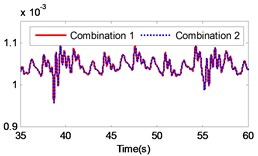
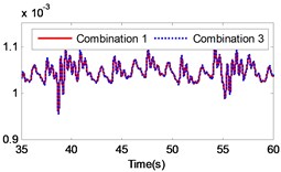
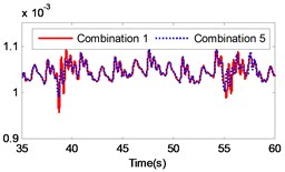
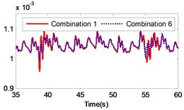
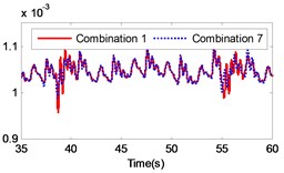
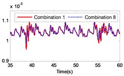
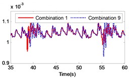
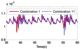
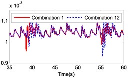
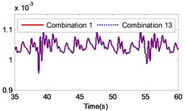
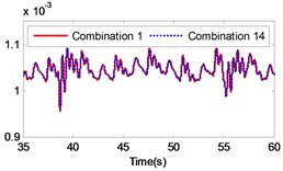
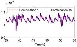
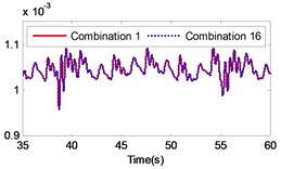
If the combination of the material of the gear pair 2 is constant, four kinds of material combinations are created for the gear pair 1. Similarly, if the combination of the material of the gear pair 1 is constant, four kinds of material combinations are also created for the gear pair 2. Thus, 16 kinds of material combinations totally exist. The specific data of the 16 combinations of materials are presented in Table 3. By setting the collision contact stiffness and the corresponding mass of each gear, the gear system under the 16 different combinations was simulated. The simulation results are illustrated in Fig. 13. The figure includes a comparison of the load response of the different gear combinations and the default material combination at the meshing impact position under large inertia. From the figure it is strongly pronounced that the impact of different material combinations on the gear transmission system varies.
By comparing the load angular velocity response of different material combinations, it is concluded that the stiffness and damping of gear pair 1 have insignificant effect on the dynamic response of the gear system, as illustrated in Fig. 13(a)-(c), (l)-(o) in Fig. 13, which changes the material of gear pair 1 and ensures that the material of gear pair 2 is unchanged, or only exchanges the material of active gear and passive gear of gear pair 2. Changing the material of gear pair 2 has a significant effect on the dynamic response of the gear system. In particular, when the material of the gear pair 2 changed to stainless steel, the angular velocity fluctuates greatly at the meshing impact. In order to investigate the influence of the material variation on the gear system intuitively, the angular velocity fluctuation value on the angular velocity curve was extracted. Additionally, the velocity fluctuation quantity under each material combination was calculated and compared to the angular velocity fluctuation under the combination of the default material. The simulation results are presented in Table 3.
According to Table 3, it is pronounced that, in the case of a constant material composition, by exchanging only the material of active gear and passive gear on the same gear pair has insignificant effect on the gear system. The fluctuation amount is almost unchanged, similar to combination 1 and combination 4, combination 1 and combination 13, combination 2 and combination 14, combination 3 and combination 15, combination 4 and combination 16, combination 5 and combination 8, combination 9 and combination 12, combination 13 and combination 16, as presented in Table 3. The material combinations of 5 to 8 fluctuate between the percentage of –40 % to –30 %, thus effectively reduce the amount of fluctuations. The common point in material combinations of 5 to 8 was that the gear material of gear pair 2 is completely titanium alloy. The material combinations of 9 to 12 fluctuate between the percentages of 30 % to 40 %, which increased the amount of fluctuations. The common point in material combinations of 9 to 12 is that the gear material of gear pair 2 is completely stainless steel.
Fig. 13Comparison of the angular velocity of different combinations at the meshing position under large inertia
a)
b)

c)
d)
e)
f)
g)
h)

i)
j)
k)
l)
m)
n)
o)
The changing of the fluctuation amount of the other combinations is insignificant, hence it can be concluded that the material of the second gear pair has a stronger influence on the dynamic response of the gear system compared to the first gear pair. In the range of 5 to 8, the volatility of the combination 6 equals –39.27 %, which is the greatest change in the fluctuation of the four combinations. In the range of 9 to 12, the volatility of the combination 11 is 35.63 %, which also constitutes the greatest change in the fluctuation of the four combinations. The gears of combination 6 are made of titanium alloy while the gears of combination 11 consist of stainless steel. It can be concluded that changing the gear material to titanium alloy can reduce the fluctuation amount of the load angular velocity and changing the gear material to stainless steel can enlarge the fluctuation amount of the load angular velocity.
Table 3Load angular velocity fluctuation at impact in different combinations of materials
Serial number | Material of gear pair 1 | Material of gear pair 2 | Minimum value of fluctuation (rad/s) | Maximum value of fluctuation (rad/s) | Fluctuation quantity | Percentage of fluctuation |
1 | Stainless steel / titanium alloy | Stainless steel / titanium alloy | 0.0009572 | 0.0010919 | 0.0001347 | – |
2 | Titanium alloy / titanium alloy | Stainless steel / titanium alloy | 0.0009587 | 0.0010919 | 0.0001332 | –1.11 % |
3 | Stainless steel / stainless steel | Stainless steel / titanium alloy | 0.0009552 | 0.0010923 | 0.0001371 | 1.78 % |
4 | Titanium alloy / stainless steel | Stainless steel / titanium alloy | 0.0009572 | 0.0010919 | 0.0001347 | 0.00 % |
5 | Stainless steel / titanium alloy | Titanium alloy / titanium alloy | 0.0009914 | 0.0010757 | 0.0000843 | –37.42 % |
6 | Titanium alloy / titanium alloy | Titanium alloy / titanium alloy | 0.0009923 | 0.0010741 | 0.0000818 | –39.27% |
7 | Stainless steel / stainless steel | Titanium alloy / titanium alloy | 0.0009900 | 0.0010783 | 0.0000883 | –34.45 % |
8 | Titanium alloy / stainless steel | Titanium alloy / titanium alloy | 0.0009914 | 0.0010757 | 0.0000843 | –37.42 % |
9 | Stainless steel / titanium alloy | Stainless steel / stainless steel | 0.0009327 | 0.0011118 | 0.0001791 | 32.96 % |
10 | Titanium alloy / titanium alloy | Stainless steel / stainless steel | 0.0009310 | 0.0011108 | 0.0001798 | 33.48 % |
11 | Stainless steel / stainless steel | Stainless steel / stainless steel | 0.0009354 | 0.0011181 | 0.0001827 | 35.63 % |
12 | Titanium alloy / stainless steel | Stainless steel / stainless steel | 0.0009327 | 0.0011112 | 0.0001785 | 32.52 % |
13 | Stainless steel / titanium alloy | Titanium alloy / stainless steel | 0.0009572 | 0.0010919 | 0.0001347 | 0.00 % |
14 | Titanium alloy / titanium alloy | Titanium alloy / stainless steel | 0.0009587 | 0.0010919 | 0.0001332 | –1.11 % |
15 | Stainless steel / stainless steel | Titanium alloy / stainless steel | 0.0009552 | 0.0010923 | 0.0001371 | 1.78 % |
16 | Titanium alloy / stainless steel | Titanium alloy / stainless steel | 0.0009572 | 0.0010919 | 0.0001347 | 0.00 % |
Therefore, to reduce the impact of the load of the gear system, it is recommended that the preferred gear material is titanium alloy, or at least to ensure that the material of gear pair 2 consists of titanium alloy. Additionally, the smaller density of titanium alloy material compared to the stainless steel, leads to lighter gear materials and increased transmission efficiency.
5. Optimization of gear system under large inertia load
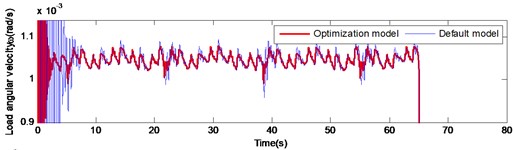
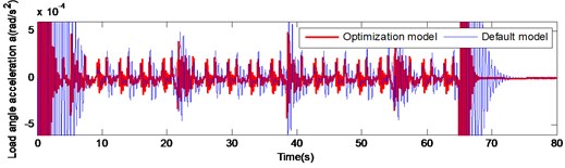
According to the analysis of the second part of the paper, it can be concluded that increasing the stiffness of the output shaft can effectively improve the decay rate of angular velocity and the angular acceleration of the output shaft at starting or braking. Furthermore, changing the gear material to titanium alloy can effectively reduce the fluctuation of the gear meshing impact. To improve the transmission accuracy of the gear reduction system of the large inertia load drive mechanism and reduce the nonlinear disturbance problem during the operation, an optimal design scheme was designed: the majority of the four gears were changed to titanium alloy and the stiffness of the output shaft was changed to 3 times higher than the original. By comparing the load angular velocity and angular acceleration of the optimization model with the default model, the feasibility of the optimization model was validated as illustrated in Fig. 14.
According to Fig. 14, the decay rate of the optimization model at starting and braking was significantly faster compared to that of the default model. At the instant of action execution (starting and braking), the velocity and acceleration can be quickly attenuated after the occurrence of fluctuations. In the gear meshing impact, the fluctuation amplitude of the optimization model was significantly lower than the default model. These alterations can improve the transmission accuracy of the system and improve significantly the nonlinear disturbance during the operation of the gear reduction system of the large inertia load drive mechanism, which validates the rationality and feasibility of the optimization scheme.
Fig. 14Comparison of load angular and angular acceleration of optimized model and default model under large inertia
a)
b)
6. Conclusions
1) For the large inertia load drive mechanism, a nonlinear dynamic model of 14-DOF spur gear system with time-varying meshing stiffness and damping, backlash and transmission error was established. The dynamic model includes torsional displacement vibration in 6 directions and radial displacement vibration in 8 directions. The reliability and efficiency of the model was verified by simulation.
2) The effect of large inertia and small inertia load on starting, normal operation and braking of gear system was investigated. It is pronounced that compared to the small inertia load system, the load angular velocity response of the drive mechanism under the large inertia load has significant hysteresis.
3) The influence of the stiffness and damping of the input, intermediate and output shaft under large inertia load was analyzed. The results depict that the changing of the stiffness of the input and the intermediate shaft has insignificant effect on the gear system under the large inertia load. Changing the output shaft stiffness has an important influence on the system and the attenuation is significantly accelerated, as the stiffness increases. In addition, the decay rate of the same shaft stiffness changing under the large inertia and small inertia load was analyzed. It is pronounced by the comparison results, that the large inertia load system is necessary to increase more times of output shaft stiffness compared to that of the small inertia load system when changing the same amount of attenuation.
4) The influence of the gear material on the system was also investigated. The angular velocity fluctuation value of the 16 kinds of material combinations was presented in Table 3. The results demonstrate that the use of titanium alloy material can effectively reduce the amplitude of the stiffness fluctuation during the meshing impact, which can improve the gear transmission precision and efficiency but on the contrary, will decrease the quality of the gear pair.
5) This paper contributes significantly on the research of the second-order spur gear nonlinear model and the large inertia load and provides an important reference for the design of the gear system. For the time-varying and nonlinear disturbance problem caused by the large inertia load space drive mechanism, theoretical reference was provided, and the optimization direction was pointed out.
References
-
Litak G., Friswell M. I. Vibration in gear systems. Chaos Solitons and Fractals, Vol. 16, Issue 5, 2003, p. 795-800.
-
Wang J., He G., Zhang J., et al. Nonlinear dynamics analysis of the spur gear system for railway locomotive. Mechanical Systems and Signal Processing, Vol. 85, 2017, p. 41-55.
-
Walha L., Fakhfakh T., Haddar M. Nonlinear dynamics of a two-stage gear system with mesh stiffness fluctuation, bearing flexibility and backlash. Mechanism and Machine Theory, Vol. 44, Issue 5, 2009, p. 1058-1069.
-
Abboudi K., Walha L., Driss Y., et al. Dynamic behavior of a two-stage gear train used in a fixed-speed wind turbine. Mechanism and Machine Theory, Vol. 46, Issue 12, 2011, p. 1888-1900.
-
Fernández A., Iglesias M., De Juan A., et al. Gear transmission dynamic: Effects of tooth profile deviations and support flexibility. Applied Acoustics, Vol. 77, Issue 3, 2014, p. 138-149.
-
Chen S., Tang J., Luo C., et al. Nonlinear dynamic characteristics of geared rotor bearing systems with dynamic backlash and friction. Mechanism and Machine Theory, Vol. 46, Issue 4, 2011, p. 466-478.
-
Parker R. G., Agashe V., Vijayakar S. M. Dynamic response of a planetary gear system using a finite element/contact mechanics model. Journal of Mechanical Design, Vol. 122, Issue 3, 2000, p. 304-310.
-
Parker R. G., Vijayakar S. M., Imajo T. Non-linear dynamic response of a spur gear pair: modeling and experimental comparisons. Journal of Sound and Vibration, Vol. 237, Issue 3, 2000, p. 435-455.
-
Vedmar L., Henriksson B. A General approach for determining dynamic forces in spur gears. Journal of Mechanical Design, Vol. 120, Issue 4, 1998, p. 593-598.
-
Rincon A. F. D., Viadero F., Iglesias M., et al. A model for the study of meshing stiffness in spur gear transmissions. Mechanism and Machine Theory, Vol. 61, Issue 61, 2013, p. 30-58.
-
Wu Y. J., Wang J. J., Han Q. K. Contact finite element method for dynamic meshing characteristics analysis of continuous engaged gear drives. Journal of Mechanical Science and Technology, Vol. 26, Issue 6, 2012, p. 1671-1685.
-
Hu Y., Shao Y., Chen Z., et al. Transient meshing performance of gears with different modification coefficients and helical angles using explicit dynamic FEA. Mechanical Systems and Signal Processing, Vol. 25, Issue 5, 2011, p. 1786-1802.
-
Shen Y., Yang S., Liu X. Nonlinear dynamics of a spur gear pair with time-varying stiffness and backlash based on incremental harmonic balance method. International Journal of Mechanical Sciences, Vol. 48, Issue 11, 2006, p. 1256-1263.
-
Chen Q., Ma Y., Huang S., et al. Research on gears dynamic performance influenced by gear backlash based on fractal theory. Applied Surface Science, Vol. 313, 2014, p. 325-332.
-
Wang G., Chen L., Yu L., et al. Research on the dynamic transmission error of a spur gear pair with eccentricities by finite element method. Mechanism and Machine Theory, Vol. 109, 2017, p. 1-13.
-
Rocca E., Russo R. Theoretical and experimental investigation into the influence of the periodic backlash fluctuations on the gear rattle. Journal of Sound and Vibration, Vol. 330, Issue 20, 2011, p. 4738-4752.
-
Rao Z., Zhou C. Y., Deng Z. H., et al. Nonlinear torsional instabilities in two-stage gear systems with flexible shafts. International Journal of Mechanical Sciences, Vol. 82, Issue 5, 2014, p. 60-66.
-
Kahraman A., Singh R. Interactions between time-varying mesh stiffness and clearance non-linearities in a geared system. Journal of Sound and Vibration, Vol. 146, Issue 1, 1991, p. 135-156.
-
Al Shyyab A., Kahraman A. Non-linear dynamic analysis of a multi-mesh gear train using multi-term harmonic balance method: sub-harmonic motions. Journal of Sound and Vibration, Vol. 284, Issue 1, 2005, p. 151-172.
-
Cui L., Huang J., Zhai H., et al. Research on the meshing stiffness and vibration response of fault gears under an angle-changing crack based on the universal equation of gear profile. Mechanism and Machine Theory, Vol. 105, 2016, p. 554-567.
-
Cui L., Zhai H., Zhang F. Research on the meshing stiffness and vibration response of cracked gears based on the universal equation of gear profile. Mechanism and Machine Theory, Vol. 94, 2015, p. 80-95.
-
Yang T., Yan S., Han Z. Nonlinear model of space manipulator joint considering time-variant stiffness and backlash. Journal of Sound and Vibration, Vol. 341, 2015, p. 246-259.
-
Xu Z. Load equivalent simulation method of ultra-large moment of inertia of space station redocking manipulator. Journal of Information and Computational Science, Vol. 12, Issue 2, 2015, p. 431-441.
-
Chen S., Zhao J., Li B., et al. Nonlinear dynamic model and governing equations of low speed and high load planetary gear train with respect to friction. International Conference on Consumer Electronics, Communications and Networks, 2011.
-
Hammami A., Rincon A. F. D., Chaari F., et al. Effects of variable loading conditions on the dynamic behaviour of planetary gear with power recirculation. Measurement, Vol. 94, 2016, p. 306-315.
-
Yang D. C. H., Lin J. Y. Hertzian damping, tooth friction and bending elasticity in gear impact dynamics. Journal of Mechanical Design, Vol. 109, Issue 2, 1987, p. 189-196.
Cited by
About this article

This work was supported by the National Natural Science Foundation of China (51575007) and the Municipal Education Commission Project of Beijing (JC001011201601).
