Abstract
A novel quasi-zero stiffness nonlinear magnetic isolator is designed by using magnetic springs in parallel with linear positive stiffness spring. Through the static analysis, the mathematical expressions of force-displacement-current and stiffness-displacement-current of the system are established, and the necessary conditions for the normal function and geometric parameters of the system are obtained. The nonlinear dynamic equations of the system under external excitation force are established. The amplitude and frequency characteristics of the system are deduced by harmonic balance method. The influence of system parameters and external excitation amplitude on the dynamic characteristics of the system is analyzed. Results showed that the vibration of the system can be controlled by controlling the electromagnet current or increasing the damping coefficient while the external excitation amplitude is kept in a certain of range. The researches provided a theoretical guidance for the design and application of the new quasi-zero stiffness nonlinear magnetic isolation system.
1. Introduction
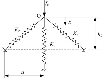
At present, low frequency vibration isolation is a major research hotspot and challengeable problem in vibration engineering field. The vibration isolation modes include passive vibration and active vibration isolation. Due to the complex structure and high cost of active vibration isolation, the passive vibration isolation is a common method. According to the theory of vibration isolation, when the excitation frequency is greater than times of the natural frequency, the system starts to isolate the harmful vibration. Therefore, the vibration isolation frequency band is wider when the natural frequency is lower. However, when the natural frequency is excessively lower, the greater static displacement will be produced. Then the contradiction of the lower natural frequency and the poorer stability resides in the system. In order to solve the problem, an isolator so-called quasi-zero stiffness (QZS) vibration isolator is proposed [1, 2]. The QZS isolator can achieve ultra-low stiffness, zero stiffness, or negative stiffness characteristics [3, 4] by designing the appropriate structural parameters. The quasi-zero stiffness (QZS) vibration isolators are usually realized by connecting a positive-stiffness mechanism with a negative-stiffness mechanism. In previous researches [5, 6], a typical configuration of the QZS isolator is shown in Fig. 1. The vertical spring acts as a positive-stiffness and the oblique springs act as a negative-stiffness. When an appropriate mass is loaded on the isolator, the springs begin to compress until the oblique springs reach the equilibrium position. At this point, the dynamic stiffness is zero if the system parameters are appropriate.
Quasi-zero stiffness vibration isolator is widely studied by a large number of scholars. Carrella et al. [7] designed a vibration isolation system consisting of three springs, obtained the nonlinear force transfer characteristics of the vibration isolation system, and explained the concept of high static stiffness and low dynamic stiffness. Kovacic et al. [8-10] optimized the structural parameters of the three-spring quasi-zero stiffness isolator and studied its bifurcation characteristics. Zhou et al. [11, 12] used the electromagnet, instead of the permanent magnet, to design a tunable magnetic isolator, which can adjust the system characteristic parameters by changing the electromagnet current. Thanh et al. [13] studied the horizontal spring by connecting the rod parallel to the vertical spring, to obtain the quasi-zero stiffness of the static equilibrium position. Niu [14] designed a new QZS isolator by connecting a disk spring with a linear spring, and studied the influence of system parameters on the transmissibility by using averaging method.
In this paper, a new type of quasi-zero stiffness nonlinear magnetic isolator is designed. A magnetic isolator, which was used as a negative stiffness mechanism, is in parallel with the positive stiffness spring. Through the analysis of static mechanics, the necessary conditions of the geometrical parameters for the system are obtained. The dimensionless force and stiffness characteristics of the system near the static equilibrium position are analyzed. The dynamical equations under external excitation are established. Then the amplitude-frequency characteristic curves and the force transmissibility of the system are obtained by using harmonic balance method. Finally, the influence of system parameters and external excitation amplitude on the dynamic characteristics of the system is analyzed.
Fig. 1Schematic diagram of a typical quasi-zero stiffness system
2. Static analysis
The typical design of a quasi-zero stiffness mechanism generally consists of a vertical spring with positive stiffness and two oblique springs with negative stiffness [5-7]. Considering a new model of the QZS isolator shown in Fig. 2(a), the quasi-zero stiffness of system is achieved by combining a vertical linear spring with two symmetrically inclined magnetic springs. The magnetic spring set consists of electromagnet and armature. The hollow ball is connected with the armature and the connecting rod can move freely in the guide. The two connecting rods and mechanical spring are hinged at the position . The vertical linear spring’s stiffness is . The length of the connecting rod is . The compressed length of the vertical spring is when the system reaches the static equilibrium position. The coordinate defines the displacement from the point .
The magnetic force, is given by [15-17]:
where is air permeability, is coil number, is magnet pole area, is air gap between armature and electromagnet, is armature displacement and is coil current.
The relational expression between the applied force and the displacement is given by:
Noting that , Eq. (2) can be written as:
Fig. 2Schematic of the QZS isolator
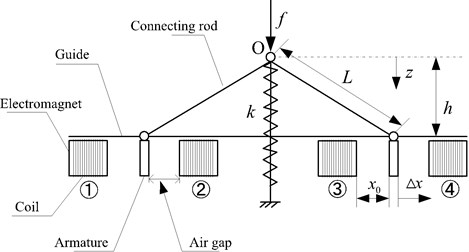
a) Structural diagram of the new QZS isolator in the initial position
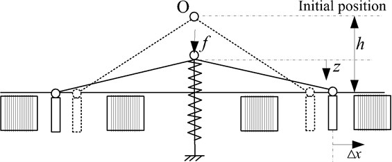
b) Schematic of the QZS isolator when system activated
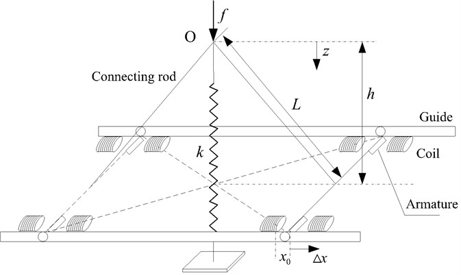
c) The model of the proposed isolator
Introducing the non-dimensional parameters:
Eq. (3) becomes:
Differentiating Eq. (4), the non-dimensional stiffness of the system can be obtained:
If Eq. (5) is considered at the static equilibrium position 1 and set to zero, the value of that ensures quasi-zero stiffness is:
According to the Fig. 1 and Eq. (3), the geometric parameters of the system must be satisfied:
Based on the analysis above, the parameters satisfying the Eq. (7) are listed in Table 1. The parameters designed in this paper are as follows: 4×10⁻⁷H/m, 470, 0.009 m2, 30000 N/m, 0.03 m, 0.07 m, 0.008 m. The current range of the coil is: 5 A, then the non-dimensional current range is: .
Table 1The parameters of the QZS isolator
H/m | 30000 N/m | ||
470 | A | 0.009 m | |
0.03 m | L | 0.07 m | |
0.008 m | 2.333 | ||
0.267 |
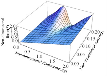
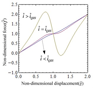
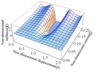
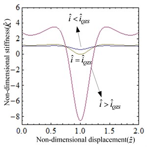
The relationship between the non-dimensional force, current and the non-dimensional displacement is plotted using Eq. (4), which is illustrated in Fig. 3. As shown in the Fig. 3, the nonlinearity of the system is getting stronger with the increase of the current. The relationship between the non-dimensional stiffness, current and the non-dimensional displacement of the system given by Eq. (5) is shown in Fig. 4, which indicates that the magnitude of the stiffness varies with the current. When the current is small, the system always exhibits positive stiffness. As the current increases to , the stiffness of the system at the static equilibrium position is zero, but in the other range, the stiffness is always positive. When the current is too large, the magnetic spring plays a leading role, and thus the system shows negative stiffness in some areas.
Fig. 3Non-dimensional force of the system: a) the surface graph of the non-dimensional force-current-displacement, b) the non-dimensional force-displacement curves for different values of i^
a)
b)
Fig. 4Non-dimensional stiffness of the system: a) the surface graph of the non-dimensional stiffness-current-displacement, b) the non-dimensional stiffness-displacement curves for several values of i^
a)
b)
By applying Taylor-series expansion,, expanding Eq. (4) at the static equilibrium position and let,an approximate expression of the non-dimensional force is obtained:
The non-dimensional stiffness is obtained by differentiating Eq. (8):
where:
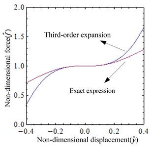
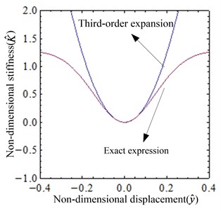
The comparison between exact expressions given by Eq. (4) and Eq. (5) and approximate expressions given by Eq. (8) and Eq. (9) of non-dimensional force and non-dimensional stiffness is shown in Fig. 5. With the increase of the displacement, the error between the exact and the approximate expression increases. When the displacement of the system at the static equilibrium position is small, the error between the exact expression and the approximate one is small, and thus the Taylor series expansion can be applied to simulate the exact expression.
Fig. 5Comparison between exact and approximate expressions of non-dimensional force and non-dimensional stiffness (i=iQZS): a) the non-dimensional force-displacement curves, b) the non-dimensional stiffness-displacement curves
a)
b)
3. Dynamic behavior of the system
3.1. Dynamic modeling
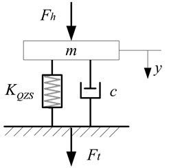
The dynamical model of the system under external excitation is shown in Fig. 6, the non-dimensional motion differentiate equation of the system is:
where:
Fig. 6System dynamical model
The solution of the system is:
For convenience, let 1:
Neglect the operation of the higher order term, the coefficients of sine and cosine in Eq. (12) should be zero:
Introduce , , where is the response amplitude of the system. Eq. (13) and Eq. (14) become:
The amplitude-frequency relation expression can be obtained by combining Eq. (15) with Eq. (1š) and using :
The transmitted force, shown in Fig. 6 is given by:
Using the Harmonic theory, suppose the response of the system has the form , substitute it to Eq. (18) and omit the higher harmonic terms. The magnitude of the transmitted force is obtained:
Thus, the force transmissibility is given:
3.2. Effects of system parameters and excitation amplitude on dynamical characteristics
Based on the analysis above, the influences of system parameters and excitation amplitude on dynamic characteristics are shown in Fig. 7-9. Three cases are analyzed in detail as follows:
(1) The damping ratio is varied. When the system parameters 0.04, 0.1, the amplitude-frequency characteristic given by Eq. (19) and the force transmissibility given by Eq. (20) for several values of the damping ratio are plotted in Fig. 7. The nonlinear characteristic of the system is gradually weakened, as shown in Fig. 7(a). With the increase of damping coefficient, the resonance peak and the jumping frequency decreases, but the jump-up frequency is not substantially varied. As seen from the Fig. 7(b), the vibration isolation effect of the system is enhanced in the low frequency band, and the effect is weakened in the high frequency range.
Fig. 7The dynamical characteristic of the system when damping ratio ξ is varied
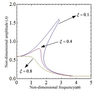
a) The amplitude-frequency curve
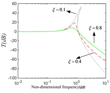
b) The force transmissibility curve
(2) The excitation amplitude parameter is varied. When the system parameters 0.04, 0.4, the amplitude-frequency characteristic given by Eq. (17) and the force transmissibility given by Eq. (22) for several values of the excitation amplitude parameter are plotted in Fig. 8. The system exhibits obvious nonlinear characteristics, as shown in Fig. 8(a). With the increase of excitation amplitude, the resonance peak, the jump-up and the jump-down frequency increase. As can be seen from the Fig. 8(b), the range of low frequency vibration isolation becomes narrower. When the external excitation frequency is higher than the jump-down frequency, the force transmissibility curve coincides. So, the vibration isolation effect is the same in this bandwidth.
Fig. 8The dynamical characteristic of the system when parameter fh is varied
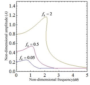
a) The amplitude-frequency curve
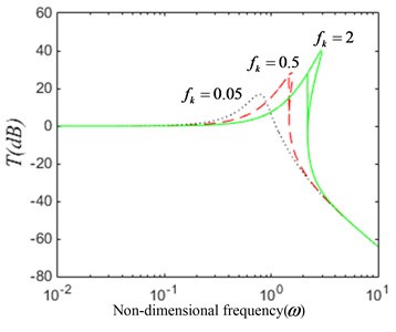
b) The force transmissibility curve
(3) The current is varied. When the system parameters 0.1, 0.4, When the system parameters 0.04, 0.1, the amplitude-frequency characteristic given by Eq. (17) and the force transmissibility given by Eq. (20) for several values of the current are plotted in Fig. 9. The nonlinear characteristic of the system is gradually enhanced, as shown in Fig. 9(a). With the increase of the current, the resonance peak decreases and the vibration isolation starting frequency decreases. As seen from the Fig. 9(b), the vibration isolation performance decreases gradually.
Fig. 9The dynamical characteristic of the system when current i is varied
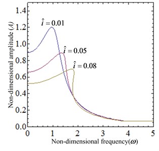
a) The amplitude-frequency curve
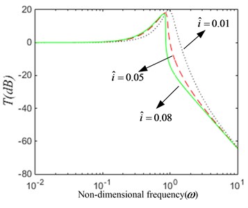
b) The force transmissibility curve
According to the analysis above, based on the proper control of the external excitation amplitude, it is possible to obtain a good vibration isolation performance by controlling the current of the system or increasing the damping coefficient of the system.
4. Conclusions
In this paper, a new nonlinear electromagnetic vibration isolator with quasi-zero-stiffness is designed. Through the static analysis, the mathematical model of force-displacement-current and stiffness-displacement-current are derived. The conditions that the geometrical parameters of the system should be satisfied to ensure proper operation of the isolator have been analyzed. The geometric dimension of the isolator is designed under these constraints. It is found that changing the current can make the system at the equilibrium position to achieve quasi-zero stiffness characteristics. Through the dynamic analysis, the study shows that under the condition of certain damping coefficient and external excitation, the appropriate current control range can be selected to restrain the amplitude of vibration effectively.
References
-
Zhang J. Z., Li D., Chen M. J., et al. An ultra-low frequency parallel connection nonlinear isolator for precision instruments. Key Engineering Materials, Vol. 257, Issue 258, 2004, p. 231-238.
-
Ronertson W. S., Kidner M. R. F., Cazzolato B. S., et al. Theoretical design parameters for a quasi-zero stiffness magnetic spring for vibration isolation. Journal of Sound and Vibration, Vol. 326, 2009, p. 88-103.
-
Ahn H. J. Performance limit of a passive vertical isolator using a negative stiffness mechanism. Journal of Mechanical Science and Technology, Vol. 22, Issue 12, 2008, p. 2357-2364.
-
Alabuzhev P., Gritchin, Kin L., et al. Vibration Protecting and Measuring Systems with Quasi-Zero Stiffness. Hemisphere Publishing Corporation, 1989.
-
Carrella A., Brennan M. J., Kovacic I., et al. On the force transmissibility of a vibration isolator with quasi-zero-stiffness. Journal of Sound and Vibration, Vol. 322, 2009, p. 707-717.
-
Carrella A., Brennan M. J., Waters T. P. Static analysis of a passive vibration isolator with quasi-zero stiffness characteristic. Journal of Sound and Vibration, Vol. 301, 2007, p. 678-689.
-
Carrella A., Brennan M. J., Waters T. P. Optimization of a quasi-zero-stiffness isolator. Journal of Mechanical Science and Technology, Vol. 21, 2007, p. 946-949.
-
Kovacic I., Brennan J. M., Waters P. T. A study of a nonlinear vibration isolator with a quasi-zero stiffness characteristic. Journal of Sound and Vibration, Vol. 315, 2008, p. 700-711.
-
Kovacic I., Brennan J. M., Lineton B. On the resonance response of an asymmetric doffing oscillator. Nonlinear Mechanics, Vol. 43, Issue 9, 2008, p. 858-867.
-
Kovacic I., Brennan J. M., Lineton B. Effect of a static force on the dynamic behavior of a harmonically excited quasi-zero stiffness system. Journal of Sound and Vibration, Vol. 325, 2009, p. 870-883.
-
Zhou N., Liu K. A tunable high-static-low-dynamic stiffness vibration isolator. Journal of Sound and Vibration, Vol. 329, 2010, p. 1254-1273.
-
Xu D., Yu Q., Zhou J., et al. Theoretical and experimental analyses of a nonlinear magnetic vibration isolator with quasi-zero-stiffness characteristic. Journal of Sound and Vibration, Vol. 332, Issue 14, 2013, p. 3377-3389.
-
Thanh D. L., Kyoung K. A. A vibration isolation system in low frequency excitation region using negative stiffness structure for vehicle seat. Journal of Sound and Vibration, Vol. 330, Issue 26, 2011, p. 6311-6355.
-
Niu Fu, Meng Lingshuai, Wu Wenjuan, et al. Design and analysis of a quasi-zero stiffness using a slotted conical disk spring as negative stiffness structure. Journal of Vibroengineering, Vol. 16, Issue 4, 2014, p. 1875-1891.
-
Daley S., Johnson F. A. Active vibration control for marine applications. Control Engineering Practice, Vol. 12, 2004, p. 465-470.
-
Yeh T. J., Ying Jer Chung, Wu W. C. Sliding control of magnetic bearing systems. Journal of Dynamic Systems, Measurement and Control, Vol. 123, 2001, p. 353-356.
-
Takeshi M., Masaya T., Daisuke K. Vibration isolation system combining zero-power magnetic suspension with springs. Control Engineering Practice, Vol. 15, 2007, p. 187-196.
Cited by
About this article

This research is supported by the National Natural Science Foundation of China (51179197, 51579242, 51509253), and by Naval University of Engineering Foundation (425517K143).
The authors would like to thank Southampton Solent University IoA course leader James Jiang Jian, for his invaluable suggestions and help.
The authors wish to thank the reviewers for their careful, unbiased and constructive suggestions, which led to this revised manuscript.
