Abstract
Rotor eccentricity is a common fault in permanent magnet synchronous motors. Its effect on the vibration and noise is thoroughly investigated in this paper. The additional force harmonics due to static eccentricity and dynamic eccentricity are firstly derived with the rotational direction of force harmonics into consideration. A finite element model is built to calculate the force and two dimensional fast Fourier transform is employed to obtain the space and frequency orders under different types of eccentricity. Then, a multiphysics model is established to predict the vibration and acoustic noise under different eccentricity types and levels. Finally, the conclusions drawn from the analytical and simulation results are partly validated by experimental test. It is found that rotor eccentricity greatly intensifies the vibration and noise due to the induced force harmonics with lower space orders. Dominant vibration and noise peaks would transfer to the frequency band in the vicinity of the lower modal frequency when eccentricity occurs.
1. Introduction
The vibration and noise problem of permanent magnet synchronous motors (PMSMs), especially which results from electromagnetic force, has been a hot topic in recent years. When compared with mechanical and aerodynamic origins, the electromagnetic origin is supposed to dominate the vibration/noise level [1] and has gained more attention [2-4]. Rotor eccentricity is a common fault in PMSM and mainly caused by manufacture/installation error and bearing wear. Rotor eccentricity will distort the spatial distribution of electromagnetic forces and then greatly change the vibroacoustic performance, since the electromagnetic vibration and noise are very affected by the spatial characteristics of the force [5, 6]. Hence, it is necessary to investigate the vibration and noise behavior under rotor eccentricity.
Based on Maxwell stress tensor method, the electromagnetic force which yields the stator vibration depends on the air-gap field. The eccentricity changes the force distribution by distorting the field. Thus, the magnetic field under the eccentricity should be figured out first to analyze the force changes. A commonly used method to consider the eccentricity is by introducing the correction factor, which is employed to study the force harmonics induced by different types of rotor eccentricity in [7-9]. It is found that static eccentricity (SE) will not yield additional force frequencies despite inducing additional space harmonics, while dynamic eccentricity (DE) will diversify both frequencies and space orders of the force harmonics. Many researches have been done to analyze the change of the force frequency at a certain spatial point or the change of the space order at a certain temporal point by using fast Fourier transform (FFT), which essentially belongs to one dimensional (1-D) analysis. However, considering the research in [10, 11], the frequency and the space order of a certain force harmonic should be obtained at the same time to discuss its contribution to the total vibration and noise. Thus, 2-D analysis instead of 1-D analysis should be adopted to get the frequency of the force harmonic with the specific space order. Moreover, it will be revealed in this research that the effect from the eccentricity also depends on the rotational direction of the induced force harmonics, which has been seldom discussed.
Regarding the influence of rotor eccentricity on the vibration and noise, the noise behavior of an induction motor under SE is investigated in [12] with the help of acoustic boundary element method (BEM) and the noise test. The result shows that the total noise increases by 10 dB due to 0.45 mm SE. Field reconstruction method is used in [13] to discuss the effect of SE on a PMSM and it is found that the overall sound power level increases by 26 dB when 40 % SE occurs. It is concluded from the above two researches that the rotor eccentricity has a great impact on the noise. However, in [12, 13], the nonuniformly distributed force on a tooth surface is simplified to single force on the surface center during the vibration and noise prediction, which is not able to exactly reflect the influence on the spatial characteristics of electromagnetic forces. According to the research in [14], this simplication of electromagnetic forces could induce significant errors in the vibration and noise calculation around modal frequencies. A semi-analytical model is presented in [15] to calculate the motor noise under eccentricity over a wide speed range and it is also found that the influence of eccentricity on noise level is attributed to its effect on the spatial distribution of force. The model is established based on the vibration and sound radiation theory of the ideal cylindrical shell model. Thus, it is only able to qualitatively discuss the impact of eccentricity on the noise radiated by the stator shaped like a cylindrical shell. Not too many researches concerning the effect of eccentricity on motor vibration and noise have been published so far. Although the effect is considerable according to the existing researches, the variation of vibration and noise peaks and the effect due to different types of eccentricity have not been thoroughly investigated.
This research is aimed to thoroughly investigate the effect of rotor eccentricity on electromagnetic force, vibration and noise. The additional harmonics of force due to rotor eccentricity are first derived. Finite element (FE) method is used to calculate the force under eccentricity. 2-D FFT is employed to decompose the force, and the relationship between the amplitude and the rotational direction of the additional force harmonics is discussed. Then, a multiphysics model is built to investigate the vibration and noise under different eccentricity types and levels. The variation of vibration/noise peaks in the calculated results is also clarified. Finally, an experimental test is conducted to validate some analytical and simulation results.
2. Electromagnetic force under rotor eccentricity
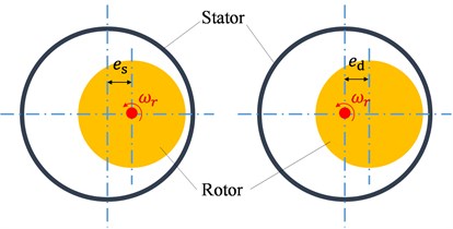
According to the position of stator axis, rotor axis and rotating axis, rotor eccentricity can be divided into two types, e.g. SE and DE. SE occurs when the rotor axis aligns with the rotating axis but misaligns with the stator axis. DE occurs when the stator axis aligns with the rotating axis but misaligns with the rotor axis. The schematic plot of SE and DE is shown in Fig. 1. and are the eccentricity length of SE and DE, respectively. The essential difference between SE and DE is that the position of the minimum air-gap length under SE keeps unchanged while that under DE rotates with the same frequency as the rotational frequency of the rotor.
Fig. 1Schematic plot of rotor eccentricity: a) SE, b) DE
2.1. Analytical derivation
In the healthy motor, the radial force on the inner surface of the stator can be expressed in the form of Fourier series and is given by:
Here, is the mechanical angle, is the time, is the space order of force. , and are the amplitude, frequency and phase angle of the force harmonic, respectively. denotes the rotating direction of the harmonic, being 1 for forward rotating and –1 for backward rotating.
Eccentricity correction factor (ECF) is employed here to derive the force harmonics under the eccentricity. ECF of SE and DE can respectively be expressed as [7]:
Here, is the rotational frequency of the rotor, , . is the effective air-gap length, which is equal to and in surface-mounted PMSM (SPMSM) and interior PMSM (IPMSM), respectively. is the thickness of PM, is the relative permeability of PM, and is the air-gap length. Due to the fact that SPMSM has a larger effective air-gap length, more distortion of the field occurs in IPMSM than SPMSM under the same eccentricity length. In other words, IPMSM is more sensitive to the eccentricity than SPMSM.
According to Eq. (1) and (2), the radial force considering SE is obtained and is given by:
Similarly, based on Eq. (1) and (3), the radial force considering DE is obtained and is expressed as:
It is found in Eq. (4) and (5) that both SE and DE have three effects on electromagnetic force. Due to the fact that the amplitudes of and are small, especially in SPMSM, the second effect is the most important because of its relatively large amplitude. With the help of Eq. (4) and (5), both of the space order and frequency of the additional force harmonics from eccentricity are clear. However, when the amplitude of the additional force harmonics is concerned, these two classical equations would not be precise enough, which is discussed in the next part.
2.2. FE analysis
A PMSM with 6 poles and 9 slots is used in this paper to investigate the effect of the eccentricity. The main parameters of the motor are listed in Table 1. Fig. 2 shows the 2-D electromagnetic model. The motor is studied under the rated working condition. The rotational speed is 3600 rpm and the load torque is 2.7 N∙m.
Fig. 22-D electromagnetic FE model
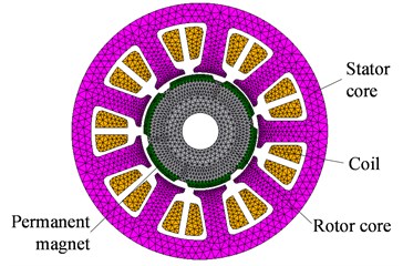
Table 1Main parameters of the motor
Symbol | Items | Values (unit) |
Number of pole pairs | 3 | |
Number of slots | 9 | |
Thickness of PM | 2.8 mm | |
Outer radius of stator | 55.5 mm | |
Stack length of stator | 55 mm | |
Inner radius of stator | 25.5 mm | |
Remnant flux density of PM | 1.2 T | |
Relative permeability of PM | 1.052 | |
Air-gap length | 1 mm | |
Slot opening width | 4 mm | |
Number of turns per coil | 35 |
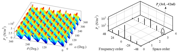
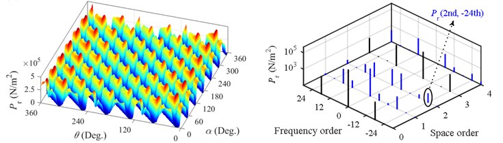
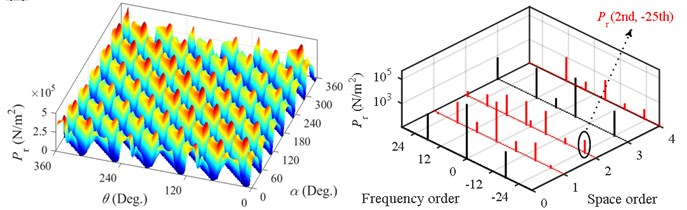
FE method is employed to calculate the radial force under the healthy case, 0.2 mm SE and 0.2 mm DE, respectively. The results are shown in Fig. 3, where means the rotational angle. It is shown that SE only changes the spatial distribution of force while DE changes both of the spatial and temporal distribution. Since the electromagnetic force varies in both space and time, the commonly used 1-D FFT is not able to acquire the space order and frequency at the same time. However, these two aspects of the force harmonic determine the spatial mode and the frequency of the vibration and noise it causes. Moreover, many researches have concluded that lower space harmonics produce higher vibration and noise [2, 5, 6]. Hence, not only the frequency but also the space order of the force harmonic should be obtained simultaneously to analyze the vibration and noise caused by this harmonic. To achieve this, 2-D FFT instead of 1-D FFT should be adopted.
Fig. 3 gives the results of 2-D FFT under different types of eccentricity. The sign of the frequency denotes the rotational direction of the force harmonic. It is noted that the 0th space force harmonics have no rotational direction. Thus, the sign of the 0th space harmonics shown in Fig. 3 makes no sense. During the 2-D FFT, a certain 0th space harmonic is divided into two parts, which are equal in the amplitude but opposite in the frequency.
In healthy PMSM with the double layer winding, the space order of the force is and the force frequency order is [16]. is the greatest common divisor and denotes integer in this paper. Thus, for the motor studied in this paper, which has 6 poles and 9 slots, the space order and frequency order of force are 3 and 6 under the healthy case, respectively. It is found in Fig. 3(b) that force harmonics with space order are induced under SE but the frequency orders of the harmonics are still 6. However, additional force frequency orders are yielded when DE occurs. So, it is possible to judge the existence of DE from the vibration or noise signal according to such unique feature of frequency.
Fig. 3Calculated radial force (left) and corresponding harmonics (right): a) healthy, b) 0.2 mm SE, c) 0.2 mm DE
a)
b)
c)
For the sake of clarity, the force harmonic with the space order and the frequency order is abbreviated as . When only the second effect of the eccentricity is considered, the force harmonics induced by SE and DE are and , respectively. It is interesting to compare the amplitude of the force harmonic having space order with that having space order . When the eccentricity occurs, force harmonics with the 2nd and 4th space order are derived from a certain original 3rd space harmonic. The derived force harmonics from the original 3rd space harmonics are listed in Table 2. It is found that the comparison between the amplitude of the 2nd space harmonic and that of the 4th space harmonic depends on the rotational direction of the original 3rd space harmonic. When the 3rd space harmonic rotates forward, the derived 2nd space harmonic is smaller than the 4th space harmonic. Inversely, when the 3rd space harmonic rotates backward, the derived 2nd space harmonic is larger than the 4th space harmonic. However, according to Eq. (4) and (5), the force harmonic having space order is equal to that having space order , which is contradictory with the above conclusion drawn from Table 2. This is because the commonly used ECF only corrects the amplitude of the flux density according to the change of air-gap length but ignores the conversion of coordinates to consider the misalignment of rotor axis and stator axis [17]. Hence, ECF can be used to discuss the space and frequency order of the force harmonics induced by eccentricity, but it is not able to analyze the amplitude of these harmonics quantificationally.
Table 2Derived force harmonics from the original 3rd space harmonics
Original space harmonics | Derived force harmonics under SE | Derived force harmonics under DE | ||
Harmonic | Amplitude (N/m2) | Harmonic | Amplitude (N/m2) | |
(3rd, 48th) | (2nd, 48th) | 11.33 | (2nd, 47th) | 11.21 |
(4th, 48th) | 48.06 | (4th, 49th) | 46.44 | |
(3rd, 30th) | (2nd, 30th) | 30.17 | (2nd, 29th) | 28.85 |
(4th, 30th) | 275.1 | (4th, 31st) | 268.3 | |
(3rd, 12th) | (2nd, 12th) | 545.3 | (2nd, 11th) | 531.7 |
(4th, 12th) | 1010 | (4th, 13th) | 991.5 | |
(3rd, –6th) | (2nd, –6th) | 918.4 | (2nd, –7th) | 917 |
(4th, –6th) | 475.1 | (4th, –5th) | 468.1 | |
(3rd, –24th) | (2nd, –24th) | 129.4 | (2nd, –25th) | 127.9 |
(4th, –24th) | 67.06 | (4th, –23rd) | 68.78 | |
(3rd, –42nd) | (2nd, –42nd) | 12.48 | (2nd, –43rd) | 12.19 |
(4th, –42nd) | 11.69 | (4th, –41st) | 11.58 | |
The effect of the eccentricity on the 0th space harmonics is a special case. When eccentricity occurs, two 1st space harmonics with different rotational directions are derived from a certain 0th space harmonic except , as shown in Table 3. The amplitudes of these two harmonics are different and also depend on the rotational direction. The harmonic rotating forward has a larger amplitude than that rotating backward.
Table 3Derived force harmonics from the original 0th space harmonics
Original space harmonics | Derived force harmonics under SE | Derived force harmonics under DE | ||
Harmonic | Amplitude (N/m2) | Harmonic | Amplitude (N/m2) | |
(0th, 0th) | (1st, 0th) | 22980 | (1st, 1st) | 22890 |
(0th, ±18th) | (1st, 18th) | 592.2 | (1st, 19th) | 582.1 |
(1st, –18th) | 347.6 | (1st, –17th) | 343.8 | |
(0th, ±36th) | (1st, 36th) | 122.4 | (1st, 37th) | 117.3 |
(1st, –36th) | 29.76 | (1st, –35th) | 29.01 | |
3. Electromagnetic vibration and noise under rotor eccentricity
3.1. Modeling of electromagnetic vibration and noise
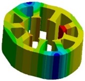
A multiphysics model is proposed in this paper to predict the vibration and noise under eccentricity. The structural model and acoustic model are shown in Fig. 4. In the structural model, which has been validated by modal test [14]. Some stator modes considering the constraints of the test bed are shown in Fig. 5. To observe modal shapes more clearly, the winding is hidden. The acoustic model has been used to calculate the noise under the healthy case, and the calculated result is validated by the noise test in [14].
Fig. 4Vibration and noise model: a) structural model, b) acoustic model
a)
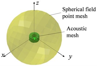
b)
Fig. 5Stator modes: a) 1267 Hz, b) 2460 Hz, c) 3259 Hz, d) 5056 Hz
a)
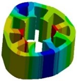
b)

c)
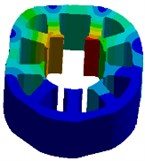
d)
3.2. Vibration and noise under different eccentricity types
Firstly, the 2-D electromagnetic model shown in Fig. 2 is used to calculate the force under the eccentricity. The force can be extended to the 3-D space under the assumption that the force distributes uniformly along the axial direction. Then, the force calculated by the electromagnetic model is applied to the structural model. Finally, the structural vibration and the acoustic noise are calculated by using mode superposition method and acoustic BEM, respectively. The proposed multiphysics model considers the spatial characteristics of the force on teeth surface with the help of the nodal force transfer method in [14] and [16]. So, the spatial distribution changes of the electromagnetic force due to the eccentricity are accurately taken into account. The vibration and noise prediction is performed in LMS Virtual.lab.
Fig. 6 gives the vibration and noise under the healthy case, 0.2 mm SE and 0.2 mm DE. It is shown that great changes can be found when the eccentricity occurs.
Fig. 6Vibration and noise comparison under different eccentricity types: a) vibration, b) noise
a)
b)
Under the healthy case, the highest noise peak appears at 2520 Hz. Fig. 7(a) shows the spatial mode of vibration/noise at this frequency. Three spatial periods can be found, which indicates that the vibration/noise at this frequency is induced by the 3rd space harmonic with the same frequency, i.e. . Although this harmonic has a small amplitude, it is still able to yield a considerable vibration/noise peak because it is close to the 3rd circumferential mode at 2460 Hz.
When SE occurs, the dominant vibration and noise peak appears at 1440 Hz. The spatial mode of the vibration and noise at 1440 Hz is shown in Fig. 7(b). Two spatial periods can be observed, which explains that the vibration/noise peak at 1440 Hz is induced by rather than . Since the force harmonic induced by SE is close to the 2nd circumferential mode at 1267 Hz, a significant vibration/noise peak is found at 1440 Hz due to the occurrence of resonance. When DE occurs, the dominant vibration and noise peak transfers to 1500 Hz. Two spatial periods are found in the spatial mode of the vibration/noise at 1500 Hz, as shown in Fig. 7(c). Similarly, this illustrates that the vibration and noise at 1500 Hz are attributed to .
From the above analysis, it is concluded that the dominant vibration and noise peak transfers to the frequency band around the lower modal frequency when the eccentricity occurs, because force harmonics with lower space orders are induced. In the motor studied in this paper, additional 2nd space harmonics are induced by eccentricity, the vibration and noise peaks around the 2nd modal frequency stand out.
Fig. 7Spatial mode of the vibration and noise at the peak frequency (on the left is vibration and on the right is noise): a) healthy motor at 2520 Hz, b) 0.2 mm SE at 1440 Hz, c) 0.2 mm DE at 1500 Hz
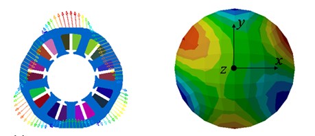
a)
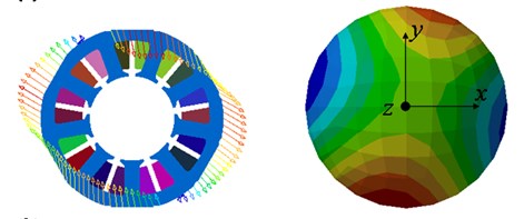
b)
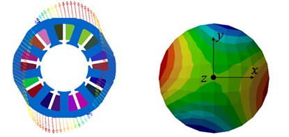
c)
When DE occurs, additional vibration/noise harmonics with frequency orders are induced. Some significant harmonics are listed in Table 4. By comparing the harmonics with the harmonics, it is concluded that the former has a larger amplitude than the latter under the same value of . This can be well explained by the amplitude and the space order of the responsible force harmonics, which are also listed in Table 4.
Table 4Order vibration and noise induced by dynamic eccentricity
Original frequency order | Additional order vibration/noise due to DE | |||
Frequency order | Vibration (m/s2) | Noise [dB(A)] | Responsible force harmonic | |
18 | 17 | 0.070 | 16.12 | (1st, –17th) |
19 | 0.074 | 21.96 | (1st, 19th) | |
24 | 23 | 0.42 | 31.64 | (4th, –23rd) |
25 | 6.23 | 56.82 | (2nd, –25th) | |
30 | 29 | 0.096 | 22.61 | (2nd, 29th) |
31 | 0.31 | 28.86 | (4th, 31st) | |
42 | 41 | 0.037 | 12.48 | (4th, –41st) |
43 | 0.24 | 29.93 | (2nd, –43rd) | |
From Table 2 it is found that is smaller than , which results in a smaller 17thorder vibration/noise than 19thorder vibration/noise. Because has a lower space order and larger amplitude than , the 25th order vibration/noise is much higher than the 23rd order vibration/noise. In the same way, the difference between the 41st and 43rd order vibration/noise can also be explained. Although has a lower space order than , the amplitude of the former force harmonic is quite lager than the latter one. Finally, induces a larger vibration/noise than .
3.3. Vibration and noise under different eccentricity lengths
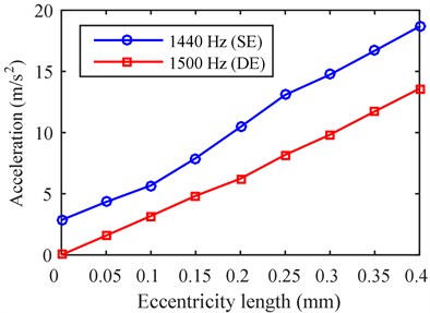
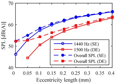
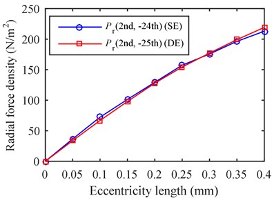
The vibration/noise and the overall SPL under different eccentricity levels are shown in Fig. 8. Since from SE and from DE increase almost linearly with the eccentricity length, as shown in Fig. 9, the vibration peak at 1440 Hz under SE and that at 1500 Hz under DE also increase linearly. However, the noise peak at 1440 Hz under SE and that at 1500 Hz under DE are more sensitive to the variation of eccentricity length when the eccentricity level is low. It is noted that although the amplitude of from SE is almost equal to that of from DE, the former harmonic yields a larger vibration and noise, because it is closer to the 2nd modal frequency.
Fig. 8The relation variation between vibration/noise and eccentricity length: a) vibration peak, b) noise
a)
b)
Fig. 9The relation variation between force amplitude and eccentricity length
The noise level increases greatly when eccentricity occurs. Fig. 8(b) shows the overall SPL under 0.4 mm SE and 0.4 mm DE increase by 14 dB(A) and 11 dB(A), respectively. This enormous effect is attributed to the lower space force harmonics induced by the eccentricity. Hence, any type of eccentricity should be avoided as far as possible to mitigate the motor noise.
4. Experimental analysis
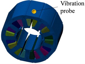
Rotor eccentricity is generally induced by manufacturing error, installation error and bearing wear. It is a difficult job to create an artificial eccentricity with a certain type and length. The schematic plot of the test bed used in this research is shown in Fig. 10. The stator is located in a ring and is clamped by two blocks. The rotor spindle is connected with the dynamometer through an elastic coupling. A noise enclosure is used to isolate the noise from the dynamometer and the coupling. An acceleration sensor and a microphone are used to measure the radial vibration and the near field noise, respectively. The outside diameter of the rotor spindle is redesigned to be slightly smaller than the inside diameter of the bearing, which will yield a certain level of DE.
Fig. 10Schematic plot of vibration and noise test
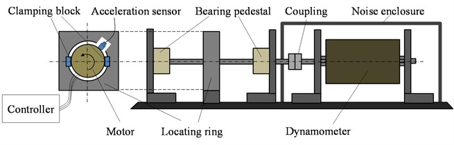
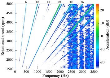
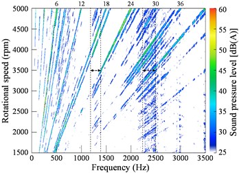
Fig. 11 shows the color map of vibration and noise during run-up from 1500 rpm to 5000 rpm. In the test, the vibration and noise signals are collected and analyzed in LMS Test.lab. In this software, the decibel value of the acceleration is calculated by:
Here, is the acceleration, and is the decibel value.
Since the motor has 6 poles, 6-th order vibration/noise can be found. Obviously, these orders result from the electromagnetic force under the healthy case. In addition, some and order components can also be observed, which mainly include the 13th, 19th, 25th, 31st order vibration and the 5th, 7th, 8th, 17th, 19th, 25th, 26th, 31st, 35th, 37th order noise. According to the force frequency changes due to the rotor eccentricity, which are discussed in section 2, these and orders coincide with the frequency orders of the force harmonics induced by DE. Hence, it is possible to diagnose DE by such additional vibration or noise orders. It is noted that some low order noise can be found in the tested noise, which results from mechanical origins and are mainly produced by the unbalanced rotor and rolling bearings. Moreover, when the electromagnetic force passes through the stator modes in Fig. 5(a) and Fig. 5(b), resonance occurs with considerable noise observed, as shown in Fig. 11(b).
Fig. 11Color map of the vibration and noise during run-up: a) vibration, b) noise
a)
b)
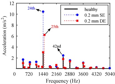
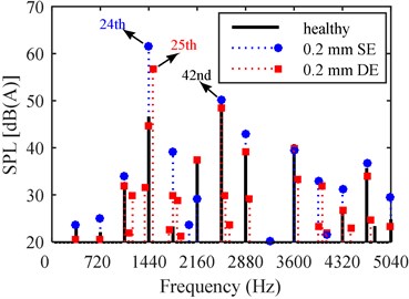
Fig. 12 and Fig. 13 compare the vibration/noise having frequency order with that having frequency order . It is found that the vibration/noise with the 19th order is larger than that with the 17th order, and the vibration/noise with the 25th order is larger than that with the 23rd order, which agrees well with the comparison in Table 4. Moreover, because and have different space orders, both of the simulation and test results show that the difference between the 23rd and 25th order vibration/noise is more significant than that between the 17th and 19th order vibration/noise.
Fig. 12Order vibration comparison: a) 17th vs. 19th, b) 23rd vs. 25th
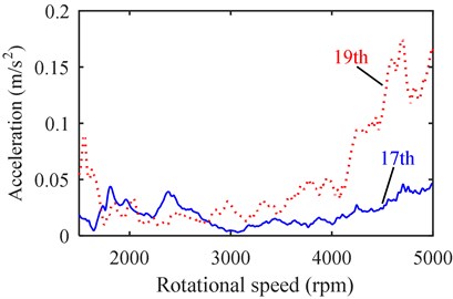
a)
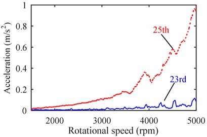
b)
Fig. 13Order noise comparison: a) 17th vs. 19th, b) 23rd vs. 25th
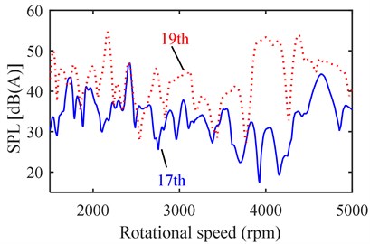
a)
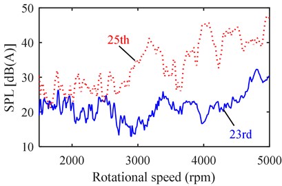
b)
5. Conclusions
A multiphysics model is proposed to investigate the influence of rotor eccentricity on electromagnetic force, vibration and noise of PMSMs. Different types and levels of eccentricity are considered. An experimental test is also conducted to validate some analytical and simulated results. The following conclusions are drawn according to the research in this paper.
a) The enormous effect of rotor eccentricity on the vibration and noise level is attributed to the induced force harmonics with lower space orders. When eccentricity occurs, dominant vibration and noise peaks would transfer to the frequency band in the vicinity of the lower modal frequency. In addition, the lower space harmonics caused by static and dynamic eccentricity have the same amplitude and space order under the same eccentricity length. Thus, the increased vibration/noise level brought by static and dynamic eccentricity depends on the closeness degree between the frequency of the induced force harmonic and the lower modal frequency.
b) Unlike static eccentricity, which only changes the spatial distribution of the radial force, dynamic eccentricity will result in additional frequency components with orders . But the space order as well as the amplitude of the and the order force can be different, which leads to the difference in the vibration/noise they cause. Both of the simulation and test results show that the order vibration/noise is larger than the order vibration/noise when dynamic eccentricity occurs, which can be explained by the differences in the space order and amplitude of the responsible force harmonics. Moreover, it is found that the difference in the space order is more critical.
References
-
Islam R., Husain I. Analytical model for predicting noise and vibration in permanent-magnet synchronous motors. IEEE Transactions on Industry Applications, Vol. 46, Issue 6, 2010, p. 2346-2354.
-
Yang H., Chen Y. Influence of radial force harmonics with low mode number on electromagnetic vibration of PMSM. IEEE Transactions on Energy Conversion, Vol. 29, Issue 1, 2014, p. 38-45.
-
Tsoumas I. P., Tischmacher H. Influence of the inverter’s modulation technique on the audible noise of electric motors. IEEE Transactions on Industry Applications, Vol. 50, Issue 1, 2014, p. 269-278.
-
Saito A., Suzuki H., Kuroishi M., Nakai H. Efficient forced vibration reanalysis method for rotating electric machines. Journal of Sound and Vibration, Vol. 334, 2015, p. 388-403.
-
Valavi M., Nysveen A., Nilssen R., Lorenz R. D., Rolvag T. Influence of pole and slot combinations on magnetic forces and vibration in low-speed PM wind generators. IEEE Transactions on Magnetics, Vol. 50, Issue 5, 2014, p. 1-11.
-
Islam M., Islam R., Sebastian T. Noise and vibration characteristics of permanent magnet synchronous motors using electromagnetic and structural analyses. IEEE Transactions on Industry Applications, Vol. 50, Issue 5, 2014, p. 3214-3222.
-
Gieras J. F., Lai J. C., Wang C. Noise of Polyphase Electric Motors. CRC/Taylor and Francis, 2006.
-
Jover Rodríguez P. V., Belahcen A., Arkkio A., Laiho A., Antonino-Daviu J. A. Air-gap force distribution and vibration pattern of induction motors under dynamic eccentricity. Electrical Engineering, Vol. 90, Issue 3, 2008, p. 209-218.
-
Ebrahimi B. M., Faiz J. Configuration impacts on eccentricity fault detection in permanent magnet synchronous motors. IEEE Transactions on Magnetics, Vol. 48, Issue 2, 2012, p. 903-906.
-
Weilharter B., Biro O., Lang H., Ofner G., Rainer S. Validation of a comprehensive analytic noise computation method for induction machines. IEEE Transactions on Industrial Electronics, Vol. 59, Issue 5, 2012, p. 2248-2257.
-
Fakam M., Hecquet M., Lanfranchi V., Randria A. Design and magnetic noise reduction of the surface permanent magnet synchronous machine using complex air-gap permeance. IEEE Transactions on Magnetics, Vol. 51, Issue 4, 2015, p. 1-9.
-
Do-Jin K., Hae-Joong K., Jung-Pyo H., Chul-Jun P. Estimation of acoustic noise and vibration in an induction machine considering rotor eccentricity. IEEE Transactions on Magnetics, Vol. 50, Issue 2, 2014, p. 857-860.
-
Torregrossa D., Khoobroo A., Fahimi B. Prediction of acoustic noise and torque pulsation in pm synchronous machines with static eccentricity and partial demagnetization using field reconstruction method. IEEE Transactions on Industrial Electronics, Vol. 59, Issue 2, 2012, p. 934-944.
-
Lin F., Zuo S., Deng W., Wu S. Modeling and analysis of electromagnetic force, vibration and noise in permanent-magnet synchronous motor considering current harmonics. IEEE Transactions on Industrial Electronics, Vol. 63, Issue 12, 2016, p. 7455-7466.
-
Rezig A., Mekideche M. R., Djerdir A. Impact of eccentricity and demagnetization faults on magnetic noise generation in brushless permanent magnet DC motors. Journal of Electrical Engineering and Technology, Vol. 6, Issue 3, 2011, p. 356-363.
-
Zuo S., Lin F., Wu X. Noise analysis, calculation, and reduction of external rotor permanent-magnet synchronous motor. IEEE Transactions on Industrial Electronics, Vol. 62, Issue 10, 2015, p. 6204-6212.
-
Rahideh A., Korakianitis T. Analytical open-circuit magnetic field distribution of slotless brushless permanent-magnet machines with rotor eccentricity. IEEE Transactions on Magnetics, Vol. 47, Issue 12, 2011, p. 4791-4808.
Cited by
About this article

This work was fully supported by a Grant (Project 51375343) from the National Natural Science Foundation of China.
