Abstract
Finite element (FE) models are utilized to investigate the influence of preload force and the stress stiffening on the dynamic characteristics of a thin-walled rectangular plate. An experimental platform system is established to obtain the dynamic characteristics of the specimen using the resonance method. Simulation and experimental results agree well with each other, which validates the effectiveness of the FE model. The results show that the preload force not only improves the overall dynamic performances of the thin-walled plate but also contributes to the local stiffness of the loading position because of the generation of stress.
1. Introduction
At present, thin-walled structures are widely used in aerospace, civil, and automotive industries because of their exceptional strength and light weight [1]. However, local low-rigidity positions are especially vulnerable to vibrations and deformations when dynamic and static loads are applied [2]. In the machining procedure, cutting force usually causes local vibration and deformation of thin-walled parts due to the low-rigidity, which is one of the main causes of the dimensional deviations [3]. In order to enhance the processing quality, therefore, it is important to investigate and improve the dynamic performances of the thin-walled parts. Some scholars and engineers are interested in controlling and reducing the vibration and deformation of the thin-walled structures [4-8].
Wu [9] developed complete-similitude scale models to predict the vibration characteristics of the elastically restrained flat plates subjected to dynamic loads. Huang et al. [10] established the characteristic equation of free vibration using Green’s function. Breslavsky et al. [11] investigated static deflection, as well as free and forced large-amplitude vibrations, of thin rectangular rubber plates under uniformly distributed pressure. Duan et al. [12] presented a novel formulation using the discrete singular convolution for free vibration analysis of circular thin plates with uniform and stepped thickness. Particularly, Gorman et al. [13-17] contributed significantly to the research on rectangular plate vibration under different boundary conditions.
Besides, Guo [18] presented the displacement field reconstruction method to acquire plate dynamic behaviors in a machining process. Zappino, Cavallo, and Carrera [19, 20] investigated the static and dynamic characteristics of reinforced thin-walled plates and shells using FE models. Mali and Singru [21] also developed an energy method to obtain analytical frequencies of the perforated plates with clamped edge and support conditions.
Moreover, some researchers found that the mechanical behavior of thin-walled parts can be enhanced when the stress is induced by external thermal and mechanical loads [22]. The enhancement of the stiffness caused by the induced stress is called as stress stiffening effects. Thus, inducing the stress caused by external loads can be an effective method to improve the dynamic performances.
Oguamanam and Hansen [22] concluded that in the case of slender beams longitudinally restrained at both ends, the stress stiffening effects are very significant and must be considered, and the beam natural frequencies can be tuned by using the induced stress stiffening. Linear models for estimating the limits of elastic stability and the effects of the initial stress on structural stiffness were formulated by Szabó and Királyfalvi [23]. A technique relied on using stress stiffening to create a non-zero tensile force acting along the beam axis was proposed by Faria [24] for enhancement of buckling loads of composite beams. Padilla and Flotow [25] concluded that stress stiffening is significant to dynamic performances only when the associated zeroth-order stresses approach “buckling” stresses. By studying the stress-Stiffening effects on laminated plates with piezoelectric actuators, Almeida [26] concluded that the importance of the stress-stiffness effect depends on the magnitude of the in-phase actuation and geometric arrangement of the piezoelectric actuators, boundary conditions, geometry of the problem, and material properties. Almeida et al. [27] investigated the effects of stress stiffening on the aero-elastic stability boundary of flutter in aircraft composite components, and they found that stress stiffening can increase the rate of occurrence of flutter. Ha et al. [28] investigated the asymmetric bending of the Allomyrina dichotoma beetle’s hind wing via FE model. They found that the stressed stiffening of the membrane and the camber of the wing affect the bending asymmetry of insect wings.
Numerous studies on the dynamic characteristics of thin-walled structures have been conducted; however, according to our knowledge, the influences of the preload force and induced stress on the dynamic performances of thin-walled plates have limited reports. In this study, FE models that present the rectangular plate under different constraint conditions are established to calculate the induced stress caused by preload and vibration modes of the plates with preload force in the range of 0-200 N. An experimental platform system is established to obtain the static deformations and dynamic characteristics of a thin-walled rectangular plate with different preload forces. Eventually, the effects of the preload force and stress stiffening on the dynamic characteristics of the thin-walled plate are discussed based on simulation and experimental results.
2. Simulations and experiments
2.1. FE simulations
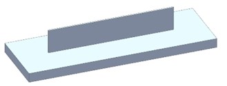
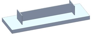
In this study, the dynamic characteristics of rectangular thin-walled plates under three different constraint conditions are investigated. The three constraint conditions are as follows: A) one long edge is free, and the other three edges are clamped; B) one long edge and one short edge are free, and the other two edges are clamped; C) one long edge is free, and the other three edges are clamped (Fig. 1).
Fig. 13-D model of the three constraint conditions
a)
b)
c)
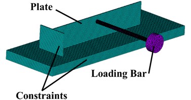
FE models that represent three constraint conditions of a rectangular plate are established in ANSYS Finite Element Method (FEM) software. A loading bar that applies the preload force in experiments is also modeled because of its low rigidity. The stress is induced by the preload in lateral direction. The material of the plate model with constraints is a 7075 aluminum alloy, and that of the loading bar is a 45 steel. The material properties and dimensional parameters are listed in Table 1.
Simulation steps can be summarized as: 1) importing the 3-D geometric model; 2) selecting the element type as Solid 185; 3) defining material properties, as shown in Table 1; 4) meshing the model with solid elements; 5) constraining all the degrees of freedom of the nodes on the bottom surface; 6) applying the preload force to the nodes around P2 position, as shown in Fig. 1; 7) solving the static problem; 8) performing the modal analysis that considers the pre-stress effect based on the static analysis results; and 9) outputting the results. The FE model of constraint condition B is shown in Fig. 2. Then, the static deformation and modal results of the rectangular thin-walled plate under different preload forces can be obtained.
In order to further investigate the influence of preload on thin-walled part dynamic performances, transient analysis is carried out based on the FE model. Sinusoidal force is applied as the periodic excitation. The functional expression of the sinusoidal force is shown in Eq. (1):
where, is the amplitude, is the frequency, and is time. is set as 100 N, and is 1000 Hz. The sinusoidal force is applied to P1 and P4 position (Fig. 1) in the opposite direction of preload. Thus, the dynamic responses under three constraint conditions with different preload forces can be obtained.
Table 1Material properties and dimensional parameters
Rectangular plate | Parameter | Loading bar | Parameter |
Elastic modulus (MPa) | 71700 | Elastic modulus (MPa) | 20600 |
Poisson ratio | 0.33 | Poisson ratio | 0.28 |
Density (kg/m3) | 2810 | Density (kg/m3) | 7800 |
Length (mm) | 200 | Length of bar (mm) | 120 |
Width (mm) | 38 | Diameter of bar (mm) | 6 |
Thickness (mm) | 2 |
Fig. 2FE model of constraint condition B
2.2. Experiments
Static-loading and dynamic experiments are conducted to measure the deformation and dynamic response of the thin-walled plate, validating the accuracy of the FE model. Subsequently, the comparison between the experimental and simulation results is made.
A monolithic specimen that has the same size and material with the FE model of constraint condition B, which can present both free and clamping edges of the rectangular thin-walled structure, is manufactured by milling.
An experimental platform system is established to perform force loading, displacement measurement, and dynamic response analysis. As shown in Fig. 3 the platform system includes the following devices: 1) force meter; 2) power amplifier; 3) vibration exciter; 4) signal generator; 5) electricity amplifier; 6) data capture card; 7) thin plate; 8) non-contact displacement sensor; 9) dial indicator; 10) static force sensor; 11) piezoelectric dynamic force sensor; 12) moving clamp; 13) computer; 14) supporter of indicator; and 15) platform.
Fig. 3Scene and schematic of the experimental equipment
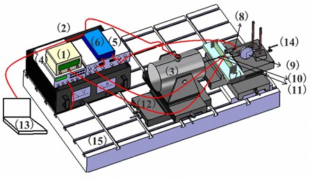
a) Schematic
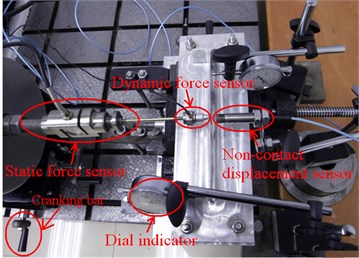
b) Scene diagram
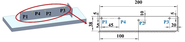
The static preload forces, which are produced by the cranking bar of a moving clamp, can be measured by the static force sensor, and the magnitude of force can be read by the force meter. The static deformation and displacement response of the thin plate are obtained by the dial indicator and non-contact displacement sensor, respectively. The measuring positions of the static deformation are shown in Fig. 1. P1, P2, and P3 are the three measuring points. The preload force is applied to the same point as P2 on the other side of the specimen.
In the experiments, the specimen is mounted on the platform, and the other devices are arranged, as shown in Fig. 3(b). The static preload force is gradually added via the moving clamp until the force meter reading is equal to the required magnitude. Then, the static deformations are obtained by reading the dial indicators.
The preload force is remained stable; simultaneously, a sine-swept vibration test is performed to analyze the dynamic response using the resonance method. The harmonic load is generated by a vibration exciter, and its value is measured by the dynamic force sensor. The frequency range is from 100-2000 Hz. The force and displacement signals are considered as input and output, respectively. Simultaneously, the transfer function analysis is conducted based on the data acquisition and signal processing system (China Orient Institute of Noise and Vibration). Consequently, the dynamic response can be obtained.
Fig. 4Static deformation results under constraint condition B
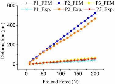
a) Simulation and experiment results
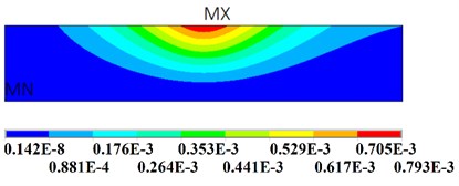
b) Deformation contour with 200 N preload force
3. Results and discussions
As shown in Fig. 4(a), the FEM static deformation and experimental results agree with each other under constraint conditions A, B, and C. The linear relationship between the deformation and preload force (Fig. 4(a)) can be easily obtained, which demonstrates that only the elastic deformation and stress are generated during the loading process. The deformation contour is shown in Fig. 4(b).
The maximum equivalent stress has a linear relationship with the preload force (Fig. 5(a)), and the maximum stress of the plate occurs at the interface of the plate and the bottom constraint (Fig. 5(b)). The maximum stress values under different constraint conditions are close, which is in accordance with Saint-Venant’s principle. The results indicate that the preload can generate stress in the local area around the loading position. The generation of stress is an important factor affecting dynamic performances.
Fig. 5Equivalent stress results under constraint condition B
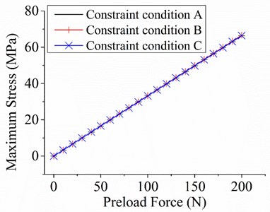
a) Stresses with different preload forces
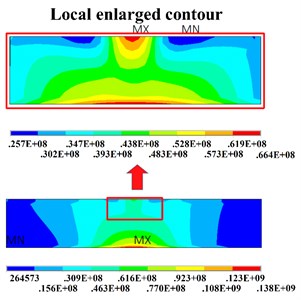
b) Stress contour with 200 N preload force
Fig. 6Relationship between natural frequencies and preload based on FEM results
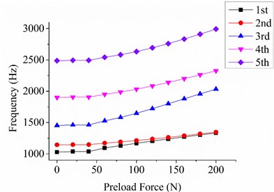
a) Constraint condition A
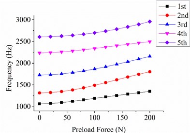
b) Constraint condition B
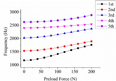
c) Constraint condition C
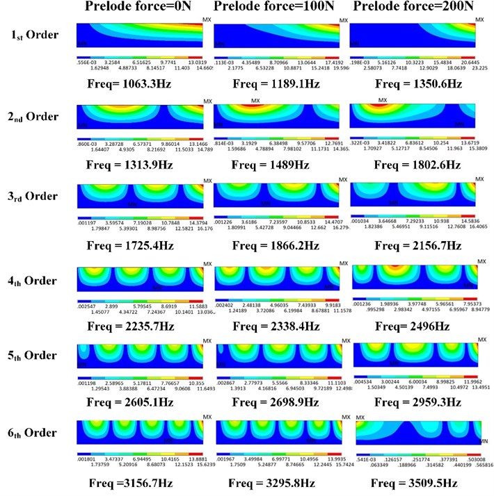
As shown in Fig. 6, the first five-order natural frequencies significantly increase with the increase in the preload force. In comparison to the first-order natural frequency without preload force, the first-order natural frequency with 200 N preload force under constraint conditions A, B, and C are increased by 29.6 %, 27.0 %, and 50.1 %, respectively. The preload force also contributes to the local stiffness. The local relative amplitude can be decreased, and the vibration area around the loading position can be transferred to other positions given the existence of the preload force (Fig. 7). The first four vibration modes of the loading bar without preload force are shown in Fig. 8. The first- and second-order natural frequencies (293.7 Hz and 294.4 Hz, respectively) of the loading bar are significantly close to each other because of their axisymmetric structure. The third- and fourth-order natural frequencies (1800.6 Hz and 1804.1 Hz, respectively) are larger than the third-order natural frequency of the plate.
Fig. 7Vibration patterns with 0, 100, and 200 N preload force under constraint condition B
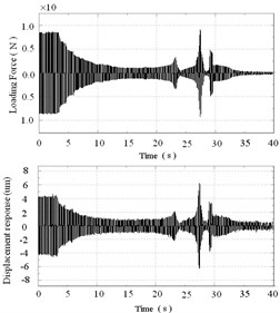
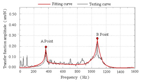
The measured input and output signals and the transfer function analysis results with 0, 100, and 200 N preload forces are respectively presented in Figs. 9-11 and Table 2. The experimental results show that the natural frequencies increase, and the amplitudes decrease when the preload force is added to the thin-walled plate. The first peak (Point A in Figs. 9-11) of the transfer function analysis result reflects the first- and second-order natural frequencies of the loading bar, which are significantly close to each other. The second peak (Point B in Figs. 9-11) reflects the first-order natural frequency of the rectangular plate. The measured results are slightly smaller than the FEM results because of the existence of structural and material damping; nevertheless, the two sets of results are in the same variation trend (Table 2).
Fig. 8First four-order vibration modes of the loading bar
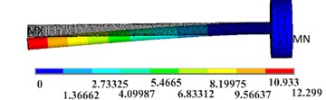
a) 1st order. Freq1 = 299.8 Hz
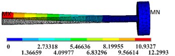
b) 2nd order. Freq2 = 300.6 Hz
c) 3rd order. Freq3 = 1864.4 Hz
d) 4th order. Freq4 = 1868.3 Hz
Fig. 9Dynamic response analysis without preload force
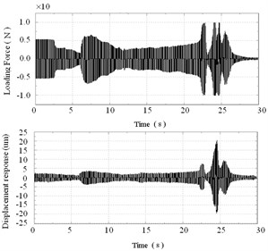
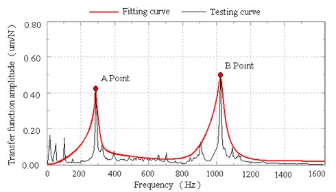
Fig. 10Dynamic response analysis with 100 N preload forces
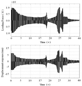
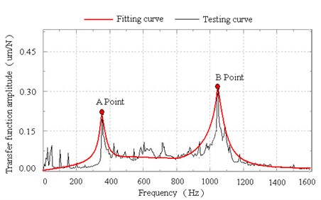
Fig. 11Dynamic response analysis with 200 N preload forces
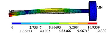
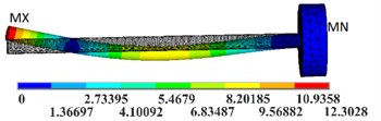
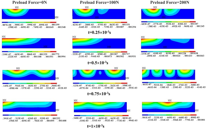
The maximum deformations (total deformation) of FE transient analysis are shown in Fig. 12, and the deformation contours at different times of constraint condition B are presented in Fig. 13. As is shown in Fig. 12, there is no obvious change in the deformation of the plate when the exciting force is applied to P1 position, which is relatively far away from the preload position (Fig. 12(a)). However, the deformations under constraint condition A, B and C all decrease with the increase of preload force magnitude when the preload is applied to P4 position, which is relatively close to the preload position (Fig. 12(b), 12(c) and 12(d)). Because the frequency of exciting force (1000 Hz) is close to the 1st order frequency of the plate, forced vibration of the plate is excited. As is presented in Fig. 13, the deformation distribution at different times is also affected due to the preload. It can be concluded that the preload force in lateral direction is more conducive to the stiffness enhancement in local area around the force position because of the stress stiffening effects.
Fig. 12Maximum deformations of thin-walled plate in one cycle
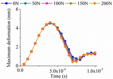
a) Sinusoidal force at P1 position under constraint condition B
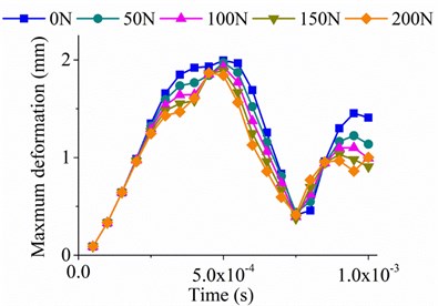
b) Sinusoidal force at P4 position under constraint condition B
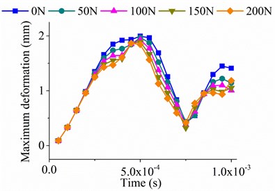
c) Sinusoidal force at P4 position under constraint condition A
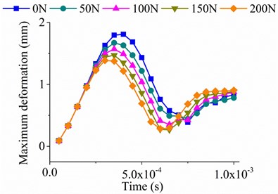
d) Sinusoidal force at P4 position under constraint condition C
Table 2Experimental results
Preload force (N) | 1st-order natural frequency (Hz) | Dynamic response in experiments (μm) | ||
FEM | Experiment | Point A | Point B | |
0 | 1063.3 | 1031.2 | 0.42 | 0.51 |
100 | 1189.1 | 1068.7 | 0.23 | 0.32 |
200 | 1350.6 | 1091.1 | 0.19 | 0.27 |
In machining process, the cutting force can be treated as sinusoidal excitation, and it leads to vibration and deformation of the workpiece, especially for the thin-walled parts. Although preload force causes local static deformation, the deformation can be precisely predicted by FE model, and the dynamic performances of the parts can be significantly improved. After calculating the deformation, tool path can be regenerated to compensate the deformation caused by preload force. Meanwhile, the vibration and deformation caused by cutting force can be reduced and controlled.
Fig. 13Deformation contours of transient analysis under constraint condition B
4. 4. Conclusions
Three FE models that present the rectangular plate under three constraint conditions are established to investigate the influence of the preload force and induced stress on the dynamic characteristics of the thin-walled rectangular plate. These models calculate the first five order vibration modes and dynamic responses under sinusoidal excitation with preload force in the range of 0-200 N. An experimental platform system is established to measure the static deformation and dynamic characteristics of an aluminum alloy thin-walled specimen with different preload forces. The FEM and experimental results are in good agreement, which validates the effectiveness of the FE model. The several conclusions drawn from the experiments are as follows:
1) A linear relationship exists among deformation, preload force, and stress. This relationship demonstrates that only elastic deformation and stress are generated during the loading process, and the deformation caused by preload force can be accurately predicted by FE model.
2) The preload force evidently improves the overall dynamic performances of the thin-walled plate because of stress stiffening effects. With the increase in the preload force, the natural frequencies of the thin-walled plate increase, and the dynamic responses decrease.
3) The preload force and the generated stress can strengthen the local stiffness of the area around the loading position. The vibration area around the loading position can be transferred to other positions because of the existence of the preload according to simulation vibration patterns.
4) In machining process of thin-walled parts, preload force can be applied to the thin-walled workpiece to reduce the vibration and deformation caused by the cutting force.
References
-
Wu Q., Li D., Zhang Y. Detecting milling deformation in 7075 aluminium alloy aeronautical monolithic components using the quasi-symmetric machining method. Metals, Vol. 6, Issue 4, 2016, p. 80.
-
Timoshenko S., Wdoinosky Krieger S. Theory of Plates and Shells Classic. Second ed., McGraw-Hill, New York, 1959.
-
Lv T., Zhang Y. D. A combined method of thermal and vibratory stress relief. Journal of Vibroengineering, Vol. 17, Issue 6, 2015, p. 2837-2845.
-
Naghdi A. E., P. M. Plasticity theory and multipolar continuum mechanics. Mathematika, Vol. 12, 1965, p. 21-26.
-
Li P., Petrinic N., Siviour C. R. Finite element modelling of the mechanism of deformation and failure in metallic thin-walled hollow spheres under dynamic compression. Mechanics of Materials, Vol. 54, 2012, p. 43-54.
-
Pagani A., Boscolo M., Banerjee J. R., Carrera E. Exact dynamic stiffness elements based on one-dimensional higher-order theories for free vibration analysis of solid and thin-walled structures. Journal of Sound and Vibration, Elsevier, Vol. 332, Issue 23, 2013, p. 6104-6127.
-
Gonçalves R., Camotim D. On the behaviour of thin-walled steel regular polygonal tubular members. Thin-Walled Structures, Vol. 62, 2013, p. 191-205.
-
Wu Q., Zhang Y., Zhang H. Dynamic characteristic analysis and experiment for integral impeller based on cyclic symmetry analysis method. Chinese Journal of Aeronautics, Chinese Journal of Aeronautics, Vol. 25, Issue 5, 2012, p. 804-810.
-
Wu J. J. The complete-similitude scale models for predicting the vibration characteristics of the elastically restrained flat plates subjected to dynamic loads. Journal of Sound and Vibration, Vol. 268, Issue 5, 2003, p. 1041-1053.
-
Huang M., Ma X. Q., Sakiyama T., Matsuda H., Morita C. Free vibration analysis of rectangular plates with variable thickness and point supports. Journal of Sound and Vibration, Vol. 300, Issues 3-5, 2007, p. 435-452.
-
Breslavsky I., Amabili M., Legrand M. Physically and geometrically non-linear vibrations of thin rectangular plates. International Journal of Non-Linear Mechanics, Vol. 58, 2014, p. 30-40.
-
Duan G., Wang X., Jin C. Free vibration analysis of circular thin plates with stepped thickness by the DSC element method. Thin-Walled Structures, Elsevier, Vol. 85, 2014, p. 25-33.
-
Singhal R. K., Gorman D. J. Free vibration of partially clamped rectangular plates with and without rigid point supports. Journal of Sound and Vibration, Vol. 203, Issue 2, 1997, p. 181-192.
-
Gorman D. J. Free vibration and buckling of in-plane loaded plates with rotational elastic edge support. Journal of Sound and Vibration, Vol. 229, Issue 4, 2000, p. 755-773.
-
Gorman D. J. Free vibration analysis of corner-supported rectangular plates with symmetrically distributed edge beams. Journal of Sound and Vibration, Vol. 263, Issue 5, 2003, p. 979-1003.
-
Gorman D. J. Accurate analytical type solutions for the free in-plane vibration of clamped and simply supported rectangular plates. Journal of Sound and Vibration, Vol. 276, Issues 1-2, 2004, p. 311-333.
-
Gorman D. J. Free in-plane vibration analysis of rectangular plates with elastic support normal to the boundaries. Journal of Sound and Vibration, Vol. 285, Issues 4-5, 2005, p. 941-966.
-
Plate T., Guo J., Member I. A., Liu R., Lee K., Asme I. Displacement field sensing and reconstruction for vibration of a thin-wall plate. IEEE International Conference on Advanced Intelligent Mechatronics, 2015, p. 1350-1355.
-
Zappino E., Carrera E., Cavallo T. Static analysis of reinforced thin-walled plates and shells by means of finite element models. Mechanics of Advanced Materials and Structures, Vol. 17, Issue 2, 2016, p. 106-126.
-
Zappino E., Cavallo T., Carrera E. Free vibration analysis of reinforced thin-walled plates and shells through various finite element models. Mechanics of Advanced Materials and Structures, Vol. 23, Issue 9, 2016, p. 1005-1018.
-
Mali K. D., Singru P. M. Determination of the fundamental frequency of perforated rectangular plates: concentrated negative mass approach for the perforation. Advances in Acoustics and Vibration, Vol. 6, Issue 1, 2013, p. 1-6.
-
Oguamanam D. C. D., Almeida S. F. M., Hansen J. S. Stress stiffening effects in laminated beams with piezoelectric actuators. Journal of Intelligent Material System and Srtuctures, Vol. 9, 1998, p. 137-145.
-
Szabo B., Kiralyfalvi G. Linear models of buckling and stress-stiffening. Computer Methods in Applied Mechanics and Engineering, Vol. 171, 1999, p. 43-59.
-
Faria A. B. On buckling enhancement of laminated beams with piezoelectric actuators via stress stiffening. Composite Structures, Vol. 65, 2004, p. 187-192.
-
Padilla C. E., Flotow A. H. Stress stiffening and approximate equations in flexible multibody dynamics. AIAA Journal, 1993, p. 154-160.
-
Almeida S. F. M. Shape control of laminated plates with piezoelectric actuators including stress-stiffening effects. AIAA Journal, Vol. 37, Issue 8, 1999, p. 1017-1019.
-
Almeida A., Donadon M. V., Faria A. R., Almeida S. F. M., The effect of piezoelectrically induced stress stiffening on the aeroelastic stability. Composite Structures, Vol. 94, 2012, p. 3601-3611.
-
Ha N. S., Truong Q. T., Goo N. S., Park H. C. Biomechanical properties of insect wings: the stress stiffening effects on the asymmetric bending of the allomyrina dichotoma beetle’s hind wing. Plos One, Vol. 8, Issue 12, 2013, p. e80689.
Cited by
About this article

This work is supported by National Science and Technology Major Project (2014ZX04001011), State Key Laboratory of Virtual Reality Technology Independent Subject (BUAA-VR-16ZZ-07), and Beijing Municipal Natural Science Foundation (3172021). The authors thank the referees of this paper for their valuable and very helpful comments.
The authors declare that there is no conflict of interest regarding the publication of this paper.
