Abstract
A hybrid system combining the energy and attitude control task uses flywheels to store energy and control the attitude of small satellites. Various journal papers containing previous works have recognized this combined architecture. However, due to the uncertainties of on-board performances, it is a challenge in terms of attitude pointing accuracy. Therefore, this paper focuses a full state-feedback control solution to increase the satellite attitude performances. Mathematical model and numerical treatments for full state-feedback control of combined energy and attitude regulating scheme for a small satellite are presented. Simulation results show that an enhanced pitch pointing accuracy can be achieved up to 0.0010 for the proposed control approach. The paper contains an over view of a flywheel architecture along with state space representation of the scheme. A brief description of conventional control scheme is also presented with sample simulated results for comparison. Design of a full state-feedback controller and analysis of simulated results are also presented to show the achieved attitude performances specifically.
1. Introduction
The paper introduces a control architecture of two-degree-of-freedom to enhance the pointing accuracy of small satellite. The architecture is constructed based on double rotating flywheel. Both energy storage and attitude control tasks are performed by this architecture at the same time. The flywheel is much better than other conventional energy storage devices. It is not sensitive on temperature variation. Its life cycle is longer and depth of discharge (DoD) is higher. The rotational kinetic energy is stored while the flywheel is rotated by an electric motor. Stored kinetic energy is used to run an electric generator to produce electricity as per demand. Although the flywheel energy storage system has high rate of charging and discharging capacity yet the construction is simple and less massive than other energy storage devices such as lithium ion battery.
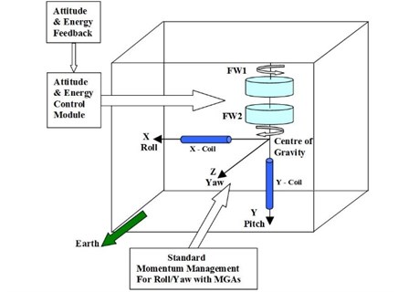
Rotating flywheels are potential tools to perform attitude control for spacecraft. It saves the mass significantly while the flywheel system functions for both energy storage and attitude control [1]. Standard double rotating flywheels architecture is shown in Fig. 1 that contains control elements, motor/generator and magnetic bearings to store energy and produce on demand attitude command. Roithmayr [2] proposed this idea and it is implemented in International Space Station (ISS) in which a composite flywheel system simultaneously satisfies the energy and attitude pointing requirement. The idea was thoroughly investigated by Varatharajoo [3, 4] in his works. The idea is tested based on two modes of flywheel inputs; one is speed-mode other is torque-mode. The authors of these papers have contributed on torque mode based combined energy and attitude control scheme design and simulation for different types of small satellites [6-10]. The types of small satellite are decided according to the mass of satellite such as, 10 kg (nano satellite), 50 kg (micro satellite) and 100 kg (enhanced micro satellite). Those works conducted a full system design and arithmetic modeling of a hybrid energy and attitude control scheme. Following the study, it shows that the proposed combined system is a promising candidate for mass budget, architecture volume, and energy consumption. In terms of attitude control performance, the numerical simulation results are presented for this combined system to meet the mission goals while using PID controller [3, 4, 6-11].
Fig. 1Satellite flywheel architecture
PID controller is one of the mostly used controllers for aerospace industries. In general, there are various techniques to tune the PID controller. A chaotic ant colony algorithm with the adaptive multi-strategies (CASOAMS) is one of those techniques to optimize the parameters of PID controller [12]. Fuzzy PID control technique is another modified PID control method and it is suitable to control a multi flexible body dynamics (MFBD) like satellite systems [13]. Uncertainties of satellite attitude error can also be reduced using incremental support learning method [14]. Perfect estimation of rotational movement is also crucial to know the current attitude of satellite to be controlled. A suitable method of motion estimation demonstrated in [15], that can be implemented to know the real-time data for satellite attitude control.
However, among several types of PID controller, a few of them is tested to enhance the pitch pointing accuracy of flywheel based combined energy and attitude control scheme for small satellite. For example, the combined architecture is demonstrated using PID-Active force control (AFC) method and obtained better enhancement of satellite attitude pointing up to 0.01° [16] for ideal case. Nevertheless, the AFC extensively depends on the active inertial measurement system which demands time to develop. Moreover, the conducted analysis was confined for speed mode control instead of torque mode. Other than the PID based controller, a optimal control technique is demonstrated to further enhancement of satellite pitch pointing performance for the same flywheel based combined scheme [17]. Purpose of this control algorithm is to minimize a quadratic cost function of dynamical system described by a set of linear differential equation. Simulated results show that the achieved pitch pointing accuracy of the satellite is enhanced up to 0.018° for ideal case.
All those techniques are not based on state space approaches to control such a hybrid system for regulating and enhancing the satellite energy and attitude performances. Therefore, here is a technical gap to design the controller for flywheel based combined architecture. Consequently, this paper attempts to implement a full state-feedback control method based on state space approach, to improve the satellite pitch pointing accuracy. Further, it can be mentioned that, the performance of energy storage and roll/yaw pointing accuracy remains optimal according to the series of works done previously; and consequently, it will not be demonstrated herein.
It can be specifically mentioned that a different method is used in this work which is dissimilar to the method used in previously published works demonstrated in [6-10, 16, 17]. Again, the new result is far better than the former results in terms of pitch pointing accuracy for small satellite control and a complete view of comparison is shown in Tabular form at the end of this paper.
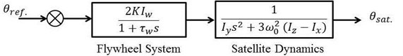
Fig. 2Simplified open-loop block diagram representation of hybrid control system
The rest of present paper is arranged as follow: The modeling of flywheel architecture has been presented in Section No. 2. The Section No. 3 briefly described the conventional method of control architecture with sample simulation result. State space representation of flywheel based hybrid system for energy and attitude control system is explained in Section No. 4. Full state-feedback controller is designed for this combined system in Section No. 5. The Section No. 6 presents the simulation and analysis of the results for pitch pointing accuracy for a small satellite 100 kg based on combined energy and attitude control scheme. Section No. 7 concluded the paper explaining enhanced performance of the proposed control method.
2. Flywheel architectural model
As shown in Fig. 1, a counter rotating high speed dual composite rotors are mounted along the same spinning axis. It contains control elements, motor-generator and magnetic for energy-attitude management [3, 6]. Basically, the solar panel will generate electricity which will be stored as kinetic energy in the flywheels. During the charging phase, the motor will speed-up both flywheels and slow-down them during the discharging phase. In order to induce the required control torque for attitude corrections, both flywheels will be rotated at different speeds. A simplified open loop model is obtained from the previous works performed [3, 6] and shown in Fig. 2. The open loop transfer function for a third order flywheel based combined energy and attitude control system is given as follows:
Here, denotes the Laplace variable and the motor-generator torque constant is assumed as unity [3, 6]. . and are reference and actual satellite pitch angle. is system response time constant and is the satellite orbit rate. stands for flywheel inertia while is for satellite moment of inertia in pitch direction. By having similar yaw and roll moments of inertias, the satellite pitch dynamics can be evaluated independently [3, 6, 7].
3. Conventional control method and architecture
Conventional methods contributed two separate method for modeling and controlling the such combined architecture for satellite energy and attitude direction: (1) speed modes based and (2) torque mode based scheme [3, 6, 7]. Torque mode based control is shown in Fig. 3. Here, the satellite attitude is influenced by the torque produced from counter rotating double flywheel mechanism. Both flywheels are responsible for energy charging and discharging phases. Figure shows that Proportional-Derivative controller is used to produce the control command, for attitude correction. Real time satellite pitch angle . is generated from start sensor or gyroscope and used as an attitude feedback to compare with the reference orientation. In the architecture, and are projection matrices to transfer the control command from satellite coordinate frame to flywheel coordinate frame. These matrices are responsible for both flywheels respectively. Equal inertia assumption is taken for roll () and yaw () direction of the satellite.
3.1. Simulation results of conventional scheme
Detail mathematical model of this conventional method is presented by [3, 6, 7]. Numerical treatment is performed for both ideal and non-ideal cases. Ideal case is defined while the external disturbances are considered only. Non-ideal case is demonstrated including both internal and
Fig. 3Conventional combined attitude and energy control architecture
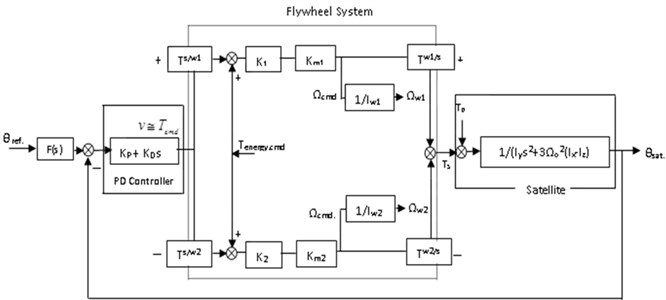
Fig. 4Simulated attitude performance in conventional control scheme
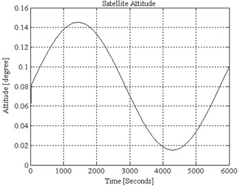
External disturbances. Proportional and derivative gain parameters are calculated for simulation purpose, which are 0.002177 and 0.02656 respectively. While the damping ratio, 1 and natural frequency, 0.1636. Simulated attitude accuracy is shown in Fig. 4. It is observed that the pitch pointing accuracy is achieved approximately 0.15°.
4. State-space modeling
Based on the block diagram shown in Fig. 2, the state variables for third order system are defined as:
Pitch angular displacement of the satellite.
Pitch angular velocity of the satellite.
Pitch angular acceleration of the satellite.
Meanwhile, the state input and state output for the third system are defined as:
Input signal into the satellite dynamics.
Output signal from the satellite dynamics.
Let:
By driving the Eq. (2) with the help of Eq. (1), it could be obtained that:
Therefore, the state-space representation of satellite dynamics in space matrix could be expressed in this form:
and:
Let’s the dynamics of the hybrid flywheel system be represented by the following state and output equations respectively:
Fig. 5Full state-feedback control diagram of a hybrid satellite system
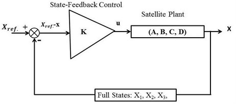
5. Full state-feedback controller design
All the state variables are feed into the input of the system through an appropriate feedback matrix in the control system design is known as the full state variable feedback control technique. Using this approach, the pole placement method can be used to design the desired controller. State controllability is required to perform the pole placement design technique. If the control input of a system can take each state variable, where 1,…, , from an initial state to a final state then the system is controllable, otherwise it is uncontrollable [18]. Therefore, the rank of the controllability matrix should be equal to the number of states in the system.
Full states feedback control diagram of a hybrid flywheel based energy and attitude regulating scheme is illustrated in Fig. 5. The reference state is defined as:
where is desired angular displacement in pitch direction of satellite. The controller is:
Note that if 0, for the gain [] the control law is applied in pole-placement algorithm. Solving for the gain , first step is to define companion matrices for and as:
where 0 is the characteristic equation of . And:
Second step is to compute , where , , …, ].
Third step is to calculate to designate the poles of to the expected locations. Introducing the control law to the Eq. (12):
Finally, to obtain the feed-back gain for the system (, ), find . It is necessary to convert → because (, ) demonstrates the original system while and are companion matrices.
6. Simulation and analysis
The combined system has three poles. Poles and are dominant poles preferred to meet the natural frequency, , and damping ratio, . Let the dominant poles be:
And:
where and is the true frequency. Other 3rd closed-loop pole, is placed at the left of the dominant poles on the real-axis.
The state vector is:
In order to provide a direct comparison with previous investigations, suitable reference mission is chosen for a small satellite [6, 16]. Its mission duration is 5 years. Orbit is Circular at 500 km with inclination of 53°, satellite mass is 100 kg for a size of 1×1×1 m3, Satellite pitch inertia is 16.9 kgm2 and system response time constant is 2 s. External disturbance is considered as the reference mission by Varatharajoo [16] for the comparison purpose.
Fig. 6Satellite attitude performance achieving up to 0.001° accuracy
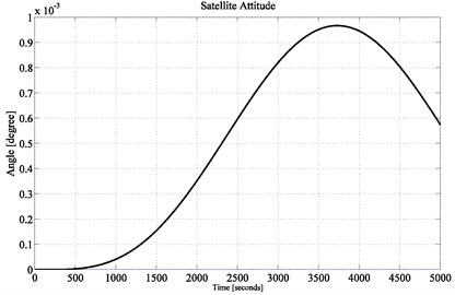
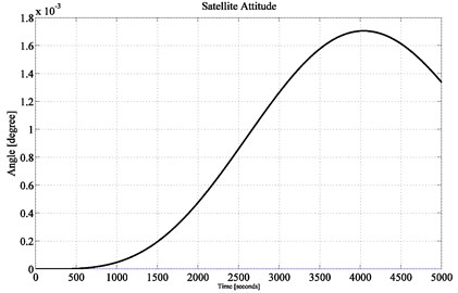
Fig. 7Satellite attitude performance achieving up to 0.0018° accuracy
The mission is to maintain the satellite pitch attitude at the reference attitude 0°, under the influence of external disturbance.
According to the above mission specifications, the control design and time-response requirements are [6, 16]: damping ratio, 1.0 and natural frequency, 0.1639 rad/s. The desired location of the closed-loop poles are at –0.1639 and –0.1639. Another pole is placed at –1.0. To achieve the prescribed pole locations using full-state feedback, the following gain vector is obtained as:
The stability of this combined energy and attitude control system can be determined from the location of poles in s plane. All the poles of a stable system are located at the left side of s pane. To examine the open-loop stability of this combined system, poles are depicted from Eq. (6). The determined open-loop poles are 0, 0 and –0.5. Because of two repeated poles on the imaginary axis, the system is unstable. This makes sense, the combined energy and attitude control system does not stay at the desired direction by itself-it distorts arbitrarily. To make the system stable, pole placement technique is implemented and those three poles are placed at –0.1639, –0.1639 and –1.0000. Subsequently, Eq. (18) expresses the required control gains of the proposed controller which satisfies the stability conditions of the system.
Fig. 6 shows the simulation result of the satellite attitude performance achieving up to 0.001° with the full state-feedback control approach unlike all other previous works performed related to this combined energy and attitude control system design. Among the previous works, the best results are obtained in the works of [16, 17], in which the maximum achievement of satellite pitch pointing accuracy were 0.01° and 0.0185° respectively. Therefore, the current investigation achieved 10 times better performance than that of in [16].
Fig. 8Satellite attitude performance (location of 3rd pole at –0.1)
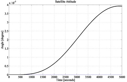
Fig. 9Satellite attitude performance (location of 3rd pole at –0.01)
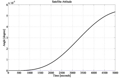
Moreover, it is observed that from 0 to 500 seconds, the proposed control system maintains 0° pointing accuracy but in the previous investigations none of them could achieve such improvement.
Since the state-feedback control design is mainly involved with pole placement technique, therefore, the obtained results are influenced by the tolerance of selecting suitable location of . It helps to confirm about the robustness of the proposed control scheme. Hence, the impact on satellite pitch pointing accuracy is observed while location of the 3rd pole, is considered at –0.5. To achieve the prescribed pole locations using full-state feedback, the following gain vector is obtained:
The obtained pointing accuracy in the simulation result of Fig. 7 is 0.0018° which is even 10 times better than that of in [17]. If the 3rd pole is moved further towards the imaginary axis, the system performance will deteriorate gradually. Evidence is shown in Fig. 8 and Fig. 9 while the location of pole is chosen at –0.1 and –0.01 respectively. For these two different pole locations, following gain vectors are obtained:
With the obtained gain vectors, simulation results show that the pitch pointing accuracy deviated from 0.001° to at best 0.005°. Hence, it proves that the proposed control design is highly robust.
Fig. 10Non-Ideal satellite attitude performance
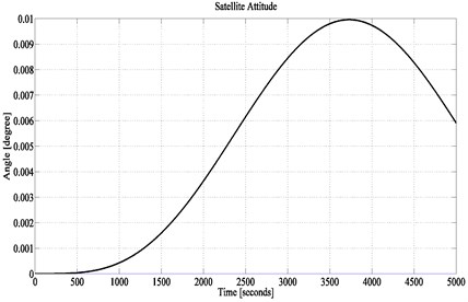
Fig. 11Ideal satellite attitude performance obtained in [16]
![Ideal satellite attitude performance obtained in [16]](https://static-01.extrica.com/articles/18066/18066-img11.jpg)
Till above, the simulation works are performed for an ideal system, in which the value of motor-generator torque constant and flywheels’ inertias are taken ideally [6, 16, 17]. Therefore, a second test is performed for a non-ideal combined system. The flywheel based system contains two major internal gain errors. In which, one is related to the motor-generator torque constants and the other one is related to flywheels’ inertias. These two internal disturbances are considered for non-ideal test cases. Hence, the small satellite is verified for a comparative motor-generator torque constant variance of 0.5 %, and a relative variance in flywheels' inertias of 0.2 % [1].
Considering these non-ideal parameters, numerical treatment is performed for satellite dynamics of the combined system. Simulation results shows in Fig. 10 that the satellite pitch pointing accuracy is reduced to 0.01° due to the non-ideal parameters. But the result is still better than any other previous investigations. For example, the same result (pitch accuracy: 0.01°) is obtained by AFC-PD control solution [16] which was tested in ideal case and shown in Fig. 11. The non-ideal treatment results were recorded for 0.3° and 0.043° in Reference [3] and [17] respectively. Therefore, the current investigation obtained better result than previously proposed scheme while considering non-ideal parameters.
A complete comparison is demonstrated in Table 1 for both ideal and non-ideal cases obtaining pitch pointing accuracy through conventional schemes and the proposed control method. Ideal case is defined while the external disturbances are considered only. Non-ideal case is demonstrated including both internal and external disturbances. The flywheel based system contains two major internal gain errors. In which, one is related to the motor-generator torque constants and the other one is related to flywheels’ inertias. These two internal disturbances are considered for non-ideal test cases. 0.2° and 0.22° is achieved for ideal and non-ideal test cases, respectively, while using proportional-integral-derivative (PID) control method. PID-active force control(AFC) method achieved pitch pointing accuracy 0.01° and 0.3° for the same test cases. Further, optimal control method obtained 0.0185° and 0.043for the similar ideal and non-ideal demonstration of combined scheme. However, the tabular comparison clearly shows the superiority of the full state feedback solution to maintain the pitch pointing accuracy for combined energy and attitude control scheme of small satellite.
Table 1A comparison of pitch pointing accuracy for the combined energy and attitude control scheme
Conventional and proposed scheme | Ideal/non-ideal case | Pitch pointing accuracy |
Mehedi-used PID controller [6] | Ideal | 0.2° |
Non-ideal | 0.22° | |
Varatharajoo-used AFC controller [16] | Ideal | 0.01° |
Non-ideal | 0.3° | |
Ying used controller [17] | Ideal | 0.0185° |
Non-ideal | 0.043° | |
Proposed full state-feedback controller | Ideal | 0.001° |
Non-ideal | 0.01° |
7. Conclusions
A pole placement with full state-feedback design is presented in this paper. The method of control solution has been tested on combined energy and attitude regulatory scheme with a selected reference mission. Results show that the full state-feedback control design performed far better than the required mission attitude accuracy when an appropriate combination of poles location are selected. The proposed method of control maintained the attitude accuracy from 0.001° to 0.005° for an ideal case. The full-state feedback control also maintained the attitude accuracy around 0.01° in a non-ideal flywheel based combined energy and attitude regulatory model. In fact, full state-feedback provides attitude pointing accuracy performances that are far better than control option [17] archiving 0.0185° and AFC-PD control solution [16] achieving 0.01° pitch pointing accuracy. Future works on other control options PI-Integer order control scheme can be investigated to provide a complete overview of the full state-feedback controllers on this combined system. Again, the proposed method based combined control scheme for satellite energy and attitude pointing is a novel initiation for further investigation towards designing a fractional order controller with state space approaches.
References
-
Guyot P., Barde H., Griseri G. Flywheel power and attitude control system (FPACS). 4th ESA Conference on Spacecraft Guidance, Navigation and Control System, Noordwijk, 1999, p. 371-378.
-
Roithmayr C. M. International Space Station Attitude Control and Energy Storage Experiment: Effects of Flywheel Torque, NASA Technical Memorandum 209100, 1999.
-
Varatharajoo R. A combined energy and attitude control system for small satellites. Acta Astronaut, Vol. 54, 2004, p. 701-712.
-
Varatharajoo R. Operation for the combined energy and attitude control system. Aircraft Engineering Aerospace Technology: International Journal, Vol. 78, Issue 6, 2006, p. 495-501.
-
Varatharajoo R. On-board errors of the combined energy and attitude control system. Acta Astronaut, Vol. 58, 2006, p. 561-563.
-
Mehedi I. M., Varatharajoo R., Harlisya H., Filipski M. N. Architecture for combined energy and attitude control system. American Journal of Applied Sciences, Science Publications, Vol. 2, 2005, p. 430-435.
-
Mehedi I. M., Varatharajoo R. Pointing performance of combined energy and attitude control system. Journal of Industrial Technology, Vol. 14, Issue 2, 2006, p. 147-160.
-
Mehedi I. M., Filipski M. N. Design of a momentum bias attitude control system with a double reaction wheel assembly. Ankara International Aerospace Conference, Ankara, Turkey, 2005.
-
Mehedi I. M., Varatharajoo R. Architecture of combined energy and attitude control system for enhanced microsatellites. Proceedings of Aerotech, Putrajaya, Malaysia, 2005, p. 133-140.
-
Mehedi I. M. Hybrid regulator system for satellite directing enactment and energy longevity. Life Science Journal, Vol. 11, Issue 3s, 2014, p. 59-67.
-
Varatharajoo R., Teckwooi C., Mailah M. Two degree-of-freedom spacecraft attitude controller. Advances in Space Research, Vol. 47, 2011, p. 685-689.
-
Wu D., Huimin Z., Jingjing L., Xiaolin Y., Yuanyuan L., Lifeng Y., Chuanhua D. An improved CACO algorithm based on adaptive method and multi-variant strategies. Soft Computing: Methodologies and Application, Vol. 19, 2015, p. 701-713.
-
Zhang S., Zhang Y., Zhang X., Dong G. Fuzzy PID control of a two-link flexible manipulator. Journal of Vibroengineering, Vol. 18, Issue 1, 2016, p. 250-266.
-
Gu B., Sheng V. S., Tay Y. T., Romano W., Li S. Incremental support vector learning for ordinal regression. IEEE Transaction on Neural Networks and Learning Systems, Vol. 26, Issue 7, 2015, p. 1403-1416.
-
Pan Z., Zhang Y., Kwong S. Efficient motion and disparity estimation optimization for low complexity multi view video coding. IEEE Transaction on Broadcasting, Vol. 61, Issue 2, 2015, p. 166-176.
-
Varatharajoo R., Teckwooi C., Mailah M. Attitude pointing enhancement for combined energy and attitude control system. Acta Astronaut, Vol. 68, 2011, p. 2025-2028.
-
Ying S. B., Varatharajoo R. Hα control option for a combined energy and attitude control system. Advances in Space Research, Vol. 52, 2013, p. 1378-1383.
-
Nise S. N. Control Systems Engineering. John Wiley and Sons, 2008.
Cited by
About this article

This work was supported by the Deanship of Scientific Research (DSR), King Abdulaziz University, Jeddah, under Grant No. (D-150-135-1437). The author, therefore, gratefully acknowledges the DSR technical and financial support.
