Abstract
The gear rattle noise of automobile transmission, which belongs to broadband noise, tends to attract the driver’s increasing attention. This paper performs a test on the noise, vibration and harshness (NVH) performance of power train in a passenger car. The results of the test show that the angular acceleration of the input shaft in the transmission increases with the increase of the angular acceleration of the flywheel, and excessive fluctuations of angular acceleration lead to the generation of the gear rattle in transmission. In this paper, a mathematic model of torsional vibration under the working conditions of acceleration, constant speed and deceleration has been established by taking a pair of helical gears as an example. The solving model of the mathematic model is set up by Matlab/Simulink and numerical solution has been solved. The theoretical analyses show that the ability of the traditional single-stage torsional vibration damper to attenuate fluctuations of angular acceleration is limited, while the multi-stage torsional vibration damper can attenuate larger fluctuations of angular acceleration, and the power train can provide good comfort and low fuel consumption. The experimental results in this paper are in accordance with above theories. Dynamic model of torsional direction of helical gears built in this paper is of great significance to the analysis of dynamic characteristics of gears. The multi-stage torsional vibration damper proposed in this paper can attenuate larger fluctuations of angular acceleration effectively, which plays an important role in controlling gear rattles, meanwhile it can enhance the riding comfort of a vehicle and reduce fuel consumption.
1. Introduction
With the rapid development of the automobile industry, the competition in the automobile market has become increasingly fierce. Consumers are more concerned about the NVH performance of the vehicle. The vibration and noise of transmission make a great contribution to the vibration and noise of the whole vehicle. As a result, in order to make a great improvement of the NVH performance of the whole vehicle, the vibration and noise of the transmission system should be controlled.
There are many factors that affect the gear rattle in the transmission, such as the angular acceleration from the engine, the vibration effect of the torsional vibration damper and the structural design parameters of the transmission [1]. Several automobile manufacturers have tried different methods to control the gear rattle noise in transmission, like replacing with high viscosity gear oil, installing gear shifting cable isolator and dual mass flywheel. These methods have been truly enhanced the NVH performance. However, they have caused the deficiency of other properties of the vehicle, such as fuel consumption rise, shift gears soft, acerbity and vehicle cost rise [2]. Thus, it has great significance to choose the appropriate method to control the transmission gear noise.
The scholars at home and abroad have done a lot of researches on the influence of fluctuation of angular acceleration on the gear rattle. In 1987, Fudala et al. used the experimental method to study the effects of factors including fluctuation of angular acceleration from engine, the inertia of the flywheel and clutch characteristics vice on gear rattle in transmission [3]. In 2000, Gaillard et al. used numerical simulation and experimental test to study the influence of clutch characteristics on transmission clatter, and it found it is an effective measure through improving clutch characteristics to control gear rattles [4]. In 2005, Chae et al. reduced the torsional stiffness of the clutch and the half shaft by the optimized structure of the clutch and the half shaft. Then the angular acceleration of the torsional reduced greatly in the sliding and running conditions [5]. In 2013, Prasad J. S. et al. reduced gear rattle noises in a passenger compartment by increasing clutch hysteresis [6]. Brancati R. et al. studied on the relationship between the speed fluctuation, the excitation frequency, the lubrication condition and the dynamic characteristics of the gear on the special test bench [7]. Rong Guo et al. discussed the effect of determination of gear rattle noise and the influence of torsional stiffness, hysteresis damping, viscous damping, stiffness transition node, damping coefficient of the active and passive gears, moment of inertia, flywheel speed and the amplitude of fluctuation of angular acceleration on gear rattle [2]. From the above, research results of domestic and foreign experts show that the fluctuation of angular acceleration of input shaft in transmission leads directly to gear rattle and it is beneficial for controlling the gear rattle in transmission by optimizing clutch parameters.
Based on the results of NVH performance test of power train in a passenger car in the phase of the trial production, this paper analyzes the percussion dynamics of transmission gear in theory. According to the specific circumstances of the passenger car, a reasonable way has been presented to control the gear rattle noise in transmission-matching of multi-stage torsional vibration damper. Both theoretical calculation and experimental verification have indicated that the matching of multi-stage torsional vibration damper can effectively attenuate the larger fluctuations of angular acceleration of input shaft, which plays an important role in controlling the transmission rattle noise.
2. NVH performance test of power train in a passenger car
The passenger car in the stage of trial was assessed primarily. The results showed that the 2nd gear, the 3rd gear, the 4th gear had clear gear rattle noise, while the 1st gear, the 5th gear and the retreat gear did not have this kind of noise obviously. In order to determine the mechanism of the gear rattle noise in transmission and find out the appropriate method to control the noise of the passenger car in a reasonable range, the NVH performance of power train in the passenger car was tested [8, 9].
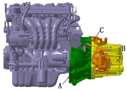
The test vehicle is equipped with a 1.8 T engine with four cylinders and manual transmission which can deliver maximum torque of 260 Nm. Tests were conducted in the vehicle semi-anechoic chamber shown in Fig. 1, in which cut-off frequency is 63 Hz and background noise is less than 20 dB (A). Selection and layout of sensors was shown in Fig. 2 and Table 1. Low noise four-wheel drive chassis dynamometer was selected, whose drum diameter is 1905 mm, rated power for a 600 kW. Tests were carried out in the conditions as follows: 1) acceleration and slide in 1st gear; 2) acceleration and slide in 2nd gear; 3) acceleration and slide in 3rd gear; 4) acceleration in 4th gear; 5. acceleration in 5th gear. LMS128 channel data acquisition system was applied, which has two-speed input channel and four-channel signal generator.
Fig. 1Tests in the vehicle semi-anechoic chamber
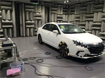
Fig. 2Sensors layout and the software in NVH testing of transmission
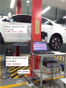
a)
b)
Table 1Information of sensors in NVH testing of transmission
Position | Sensor | Position in Fig. 2 | Type | Model | Picture |
Flywheel | Speed sensor | A | Eddy current sensors | SJ109 |  |
Input shaft | Speed sensor | B | Eddy current sensors | SJ109 |  |
Driver’s right ear | Microphone | D | Digital person foreman | HMS 4.0 |  |
Near field | Microphone | C | Sound intensity probe | GRAS 46AE |  |
Transmission Z | Acceleration sensor | C | Piezoelectric sensor | HAD/8602 |  |
Test results of 2nd gear, 3rd gear, 4th gear which had evident gear rattle noise in subjective driving evaluation are shown in Fig. 3.
Fig. 3The angular acceleration of flywheel and input shaft in 2nd gear
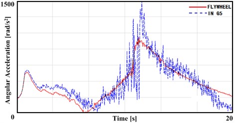
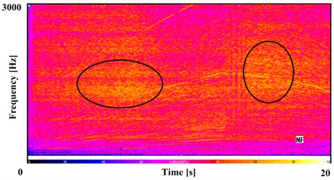
Fig. 3 shows the measured value of angular acceleration of flywheel and input shaft in the 2nd gear, in which vehicle slides after accelerates. It can be seen from the Fig. 3 that the angular acceleration of input shaft always follows the engine flywheel’s in the entire working conditions. And with the increase of the angular acceleration of input shaft, the fluctuation of the angular acceleration also increases. In the phase of transition from acceleration to slide, the average value of the angular acceleration and the amplitude of the fluctuation are to the maximum. Combined with Fig. 4, the near field noise in 2nd gear under the same condition, it can be concluded that in this stage, the transmission has a certain degree of gear rattle.
Similarly, it can be drawn from Figs. 5-6 that gear rattle produced in the transmission have the same characteristics as 2nd and 3rd gear. Namely under a certain condition, excessive fluctuation of angular acceleration leads to rattle in loose gear.
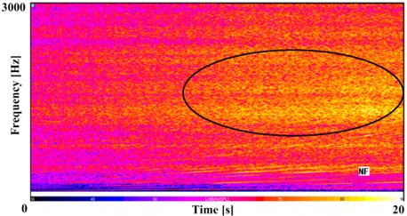
Figs. 7-8 show the test results under the condition of 4th and 5th gear. They show that in the vicinity of a particular speed, the angular acceleration of the input shaft is far greater than the angular acceleration of the flywheel of engine, accompanied by a certain gear rattle noise in transmission. However, after crossed the particular speed, the angular acceleration of input shaft reduced rapidly, and the noise of the gear rattle also decreased rapidly. It is judged that the transmission system occur resonance in the vicinity of the particular speed. The mechanism of the gear rattle is different from 2nd gear and 3rd gear.
Fig. 4The near field noise in 2nd gear
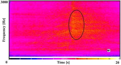
Fig. 5The angular acceleration of flywheel and input shaft in 3rd gear
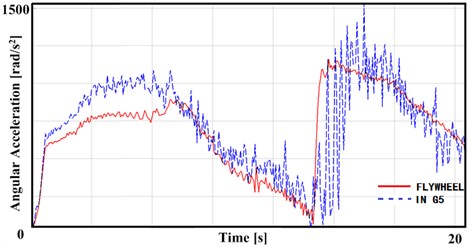
Fig. 6The near field noise in 3rd gear
In summary, from the data of NVH performance test of power train in a passenger car, the gear rattle is often driven by the excessive fluctuation of the angular acceleration of input shaft and the transmission system resonance. The gear rattle caused by the excessive fluctuation of the angular acceleration of input shaft only under certain conditions, such as the transition phase from the accelerated mode to the sliding mode. Reasonable and inevitable fluctuation of the angular acceleration from engine can be reduced to a reasonable range through the torsional vibration damper of the clutch, with no gear rattle in transmission [10].
Fig. 7The angular acceleration of flywheel and input shaft in 4th gear
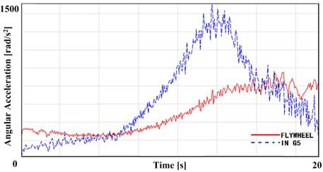
Fig. 8The near field noise in 4th gear
3. Theoretical analysis on the dynamics of gear rattles
In order to determine the generation mechanism and influencing factors of gear rattle noise in transmission for further research, the paper makes a theoretical study on gear rattle dynamics. It is clear that the manual transmission is a gear transmission system with multi axis and multi gear pairs. In order to simplify the model, the multiple pairs of gears are recognized as equivalent to a single pair of gears [11]. Mechanical model of torsional vibration of a single pair of helical gears is shown in Fig. 9.
Fig. 9Mechanical model of torsional vibration of a single pair of helical gear pairs
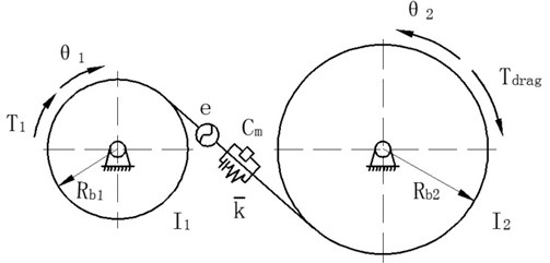
The paper analyzed the force applying on single pair of helical gear and established the dynamic model of torsional vibration [12]. Among them, expresses the displacement of driving wheel, while expresses the displacement of driven wheel. So:
Among above formulas, , stand for separately moment of inertia of the active and passive gear, , stand for separately base radius of the active and passive gear, stands for spiral angle of gear, stands for input torque, stands for retardation torque, stands for static error of gear pair, stands for mean meshing stiffness of gear pair, stands for non-linear function of clearance between the gear pair, stands for mean mesh damping of gear pair.
Dividing Eq. (1) by and dividing Eq. (2) by , then:
From , then:
Multiplying Eq. (5) by , multiplying Eq. (6) by , then:
Eq. (7) minus Eq. (8), then:
From , then:
Derived:
Transfer error in the direction of torsion of the gear system is defined as:
Then:
Eq. (12) represents the mathematical torsional vibration model of single pair of helical gear. It can be seen that the dynamic response of the gear pair to the vibration is related to the damping of the transmission system, the stiffness of the transmission system, the driving force, the load and the error of the transmission system.
There is a huge difference on the order of magnitude between damping and the stiffness. If the numerical solutions are solved directly, it will not be easy to determine the calculation step, to get accurate numerical solution, and the computation efficiency will also be pretty low. So, the paper applies dimensional method to the above differential equations [13]. Dimensional time is defined as . The displacement scale of bc is the displacement of the unilateral side clearance, then:
Take Eq. (13 - 14) into Eq. (12), then:
Among above formulas, stands for the fluctuation amplitude of meshing stiffness, stands for meshing frequency of gear pair, stand for natural frequency of gear model.
Empty or light load gears will produce gear rattle in some certain conditions [12, 14]. When transmission is in the conditions of 2nd, 3rd and 4th gears, 1st and 5th synchronizers keep uncombined, whose gears are in a state of the empty set. Compared with the 5th gear, 1st driven gear, has greater mass and larger inertia, is more prone to generate gear rattle. So, the paper takes the 1st gear parameters of transmission shown in the Table 2 into the Simulink solving model.
The certain calculation step size is 0.001, and the simulation time is unit time of 600. Among which, there are simulations of uniformly accelerated working condition during unit time of 0-200, uniform working condition during unit time of 200-400, uniformly decelerated working condition during unit time of 400-600. Simulation result is shown in Fig. 10.
Table 2The 1st gears parameters of transmission
Parameter | Value |
Number of teeth () | 17/59 |
Modification coefficient () | –0.0048/–0.2505 (mm) |
Modulus () | 2.28 |
Pressure angle () | 22.5° |
Helical angle () | 25.5° |
Tooth width () | 23/17 (mm) |
Fig. 10Dynamic response of single helical gear in different working conditions
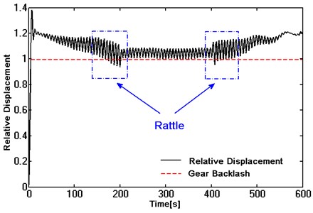
As shown in Fig. 10, in the process of dimension, the paper chose gear backlash (bc) as length ruler. In other words, unilateral clearance of gear pair means unity. When the absolute value of relative displacement between active and passive gear is less than 1, the gears will be in disjointed. Vice versa, it can be considered that gear pair will produce rattle when it is changing from disjointed into jointed.
During 1-200 unit times, the active gear accelerates uniformly. Corresponding to the acceleration condition of the vehicle, the angular acceleration from engine is not stable. With the increase of the angular acceleration from engine, the fluctuation of the angular acceleration of input shaft gets severely. At the end of accelerative motion, namely unit time of 150-200, the absolute value of relative displacement fluctuates around unity. That is to say, the gear pair is in the changing from disjointed into jointed and producing gear rattle.
During 200-400 unit times, the active gear keeps constant speed. Corresponding to cruising condition of the vehicle, engine runs stable. The fluctuation of angular acceleration from engine becomes small. The absolute value of relative displacement always greater than 1. That gear pair is in the stage of meshing without gear rattle.
During 400-600 unit times, the active gear decelerates uniformly. Corresponding to the coasting condition of the vehicle, the engine runs unstable, especially in transforming from uniform condition to coasting condition. In the early stage of coasting condition, the angular acceleration from engine and the angular acceleration of input shaft in transmission fluctuate seriously. During unit time of 400-450, the absolute value of relative displacement fluctuates around unity, namely that the gear pair is in the changing from disjointed into jointed and producing gear rattle. With the decrease of speed, the fluctuation of angular acceleration becomes flat, and the absolute value of relative displacement will always be greater than 1 without gear rattle.
From the whole simulation process, gear rattle occurs just at the stage of excessive angular acceleration and the transition phase of engine conditions. It not occurs through the whole simulation process. Due to the limited damping effect of the traditional torsional vibration damper and the characteristics of the engine, the larger fluctuation of the angular acceleration from engine is reduced incompletely by the torsional vibration damper when transmitting to input shaft in transmission. The fluctuation of the angular acceleration is still large enough to drive the gear rattle in loose gears.
To sum up, compared the theoretical simulation of torsional vibration dynamics with the results of experiments of helical gears, the traditional single-stage torsional vibration damper cannot reduce larger amplitude of fluctuation of the angular acceleration to a reasonable range when the engine under special conditions, which directly leads to the gear rattle in loose gears.
4. Influence of torsional vibration damper parameters on gear rattle
Considering that the traditional torsional vibration damper can effectively attenuate the fluctuation of the angular acceleration from engine in most cases and controlling the generation of gear rattle effectively. Just under some certain conditions of the engine, the larger fluctuation of the angular acceleration is difficult to be reduced to a reasonable range by the traditional single-stage torsional vibration damper. If improved the traditional torsional vibration damper stiffness and damping at the same time, the larger stiffness will lead to the shock in the process of power transfer, the larger damping will increase the energy consumption of the vehicle [5]. Therefore, the paper prefers to optimize the parameters of torsional vibration damper in clutch to control gear rattle [15].
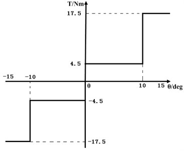
The stiffness and damping of multi-stage torsional vibration damper are nonlinear. As shown in Fig. 11 and Fig. 12, taking the stiffness and damping of double-stage torsional vibration damper as an example. When the angular acceleration from engine is relatively small, the power is transmitted through the clutch friction plate with smaller relative rotation angle of torque damper. The torsional vibration damper can attenuate the fluctuation of the angular acceleration of the engine with smaller stiffness and damping, and the vehicle power transmission has better comfort. When the engine is in a rapid acceleration or transition stage, the fluctuation of the angular acceleration of engine is larger, and torsional vibration damper relative rotation angle is larger, with triggering the secondary torque damping spring, then torsional vibration damper will use larger stiffness and damping to attenuate larger amplitude of the fluctuation of the angular acceleration [16]. The results of theoretical analysis show that the use of multi-stage torsional vibration damper can effectively attenuate the larger fluctuation of the angular acceleration of engine under certain conditions.
Fig. 11Double-stage stiffness of torsional vibration damper
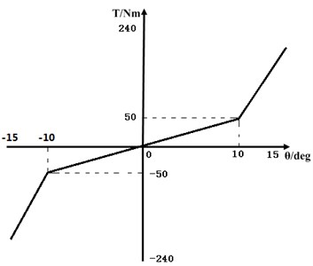
Fig. 12Double -stage damping of torsional vibration damper
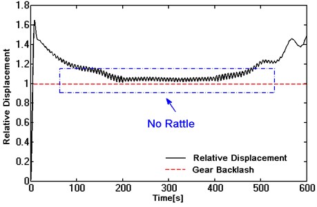
Taking spring stiffness and damping of the double-stage torsional vibration damper into the dynamic solving model of torsional vibration of single helical gear built in Eq. (15), the results of dynamic response of gear pairs are shown as follows:
It can be seen in Fig. 13 that in the whole process of simulation, the absolute value of relative displacement is always greater than 1. In other words, the gear pair is in a state of constant mesh without gear rattle. Therefore, it is effective to attenuate the fluctuation of the angular acceleration from engine and control the gear rattle noise of the transmission by matching reasonable multi-stage torsional vibration damper.
Fig. 13Dynamic response of a helical gear with double -stage torsional vibration damper
5. Experiments on improving the gear rattle of multi-stiffness torsional vibration damper
In order to verify whether multi-stage torsional vibration damper has a better effect than the traditional single-stage torsional vibration damper in terms of attenuating the larger fluctuation of the angular acceleration, the test was conducted on the angular acceleration of input shaft in transmission in the passenger car which equipped with traditional single-stage torsional vibration damper and double-stage torsional vibration damper [7, 8]. Then conditions that produce obvious gear rattle noise for testing were chosen, such as 2nd gear acceleration condition, 2nd gear coasting condition, 3rd gear coasting condition, 4th gear coasting condition. The results are shown in Figs. 14-17.
Fig. 14The angular acceleration of input shaft in 2nd gear acceleration
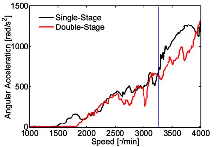
As shown in Fig. 14, the angular acceleration of input shaft measured when added traditional single-stage torsional vibration damper and double-stage torsional vibration damper respectively under 2nd gear in acceleration condition. As can be seen from Fig. 14, the angular acceleration of the input shaft with single-stage and double-stage torsional vibration damper increases similarly. When the speed of input shaft is higher over 3250 r/min, the input shaft has a higher angular acceleration. The average value of the angular acceleration of input shaft and the fluctuation amplitude of the input shaft with double-stage torsional vibration damper are obviously lower than that of the single-stage torsional vibration damper. After the speed of the input shaft is greater than 3250 r/min, the larger second stage stiffness and damping of the double-stage torsional vibration damper have taken effect. The intersection of the two curves is the starting point of the second stage torsional vibration damper.
Fig. 15The angular acceleration of input shaft in 2nd gear coasting
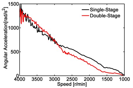
Fig. 16The angular acceleration of input shaft in 3rd gear coasting
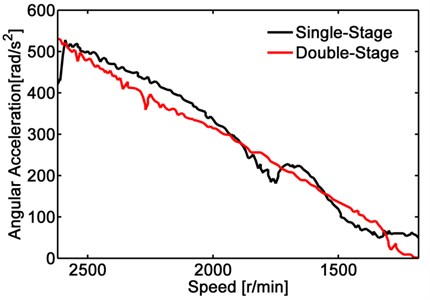
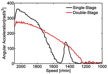
Fig. 17The angular acceleration of input shaft in 4th gear coasting
As shown in Fig. 15, the angular acceleration of input shaft measured when added traditional single-stage torsional vibration damper and double-stage torsional vibration damper respectively under 2nd gear in sliding condition. As can be seen from Fig. 15, under this condition, there is no better advantage of double-stage torsional vibration damper than the traditional single-stage torsional vibration damper in reducing average value of angular acceleration at the stage of higher angular acceleration, but the curve of the double-stage torsional vibration damper is smoother. That is to say, double-stage torsional vibration damper is better than the traditional single-stage torsional vibration damper to attenuate the fluctuation amplitude angular acceleration of engine.
Similarly, it can be seen from Fig. 16 and Fig. 17, double-stage torsional vibration damper has better effect than the traditional single-stage torsional vibration damper in attenuating the fluctuation of angular acceleration with larger amplitude under the 3rd and 4th gear in sliding conditions.
To sum up, compared with the traditional single-stage torsional vibration damper, the multi-stage torsional vibration damper has a better advantage in attenuating the larger fluctuation of angular acceleration. The attenuation of angular acceleration is more reasonable in the whole conditions with multi-stage torsional vibration damper and the reasonable attenuation of angular acceleration contributes to controlling the gear rattle [14]. So, the multi-stage torsional vibration damper has a better effect on the control of the gear rattle in transmission.
6. Conclusions
In this paper, it is found that gear rattle only occurs in some certain conditions from the analysis of NVH performance test results of power train in a passenger car. Through theoretical analysis, this paper studies the generation mechanism of gear rattle in the certain conditions and puts forward the method to control the gear rattle by the multi-stage torsional vibration damper. The experiments results show that the multi-stage torsional vibration damper can better attenuate the fluctuation of angular acceleration in some certain conditions while the comfort and fuel consumption of the vehicle are considered. Conclusions were obtained through this research are shown as follows:
1) Excessive fluctuation of angular acceleration of input shaft in transmission leads to the gear rattle noise, which is also related to both engine characteristics and clutch torsional vibration damper.
2) There will be fluctuations of angular acceleration with larger amplitude in engine certain conditions, which leads to gear rattle in the transmission. Multi-stage torsional vibration damper can effectively attenuate the fluctuation of angular acceleration of the input shaft in the certain conditions, thus control the gear rattle.
3) Compared with the method that adding stiffness and damping of traditional single-stage torsional vibration damper globally, the multi-stage torsional vibration damper has good comfort and relatively low fuel consumption in the process of power transmission in vehicle.
References
-
Brancati Renato, Rocca Ernesto, Savino Sergio A gear rattle metric based on the wavelet multi-resolution analysis: experimental investigation. Mechanical Systems and Signal Processing, 2014, p. 161-173.
-
Guo Rong, Qiu Yan, Zhang Tong, et al. The influence factors of manual transmission neutral gear on problem analysis. Journal of Jiangsu University (Natural Science Edition), Vol. 4, 2013, p. 378-383.
-
Fudala G. J., Engle T. C., Karelis A. V. A systems approach to reducing gear rattle. SAE Paper No. 870396, 1987.
-
Gaillard C. L., Singh R. Dynamic analysis of automotive clutch dampers. Applied Acoustics, Vol. 60, 2000, p. 399-424.
-
Chae C.-K., Won K.-M., Kang K.-T., et al. Measurement of transmission rattle sensitivity and calculation of driveline torsional vibration for gear rattle analysis. SAE Paper No. 2005.01.1785, 2005.
-
Prasad J. S., Damodar N. C., Naidu T. S. Clutch hysteresis maximization for elimination of gear rattle in a passenger bxis. SAE Paper, 2013, p. 1-6.
-
Brancati Renato, Rocca Ernesto, Savino Sergio, et al. Analysis of gear rattle by means of a wavelet-based signal processing procedure. Meccanica, Vol. 48, Issue 6, 2013, p. 1399-1413.
-
Acoustics-Determination of Sound Power Levels of Noise Sources Using Sound Pressure-Precision Methods for Anechoic and Hemi-Anechoic Rooms, ISO 3745-2003, 2003.
-
Acoustic-Engineering Method for the Measurement of Noise Emitted by Accelerating Road Vehicle, ISO 362-1-2005, 2005.
-
Ottewill J. R., Neild S. A., Wilson R. E. Intermittent gear rattle due to interactions between forcing and manufacturing errors. Journal of Sound and Vibration, Vol. 321, 2009, p. 913-935.
-
Singn R., Xie H., Comparin R. J. Analysis of automotive neutral gear rattle. Journal of Mechanical Design, Vol. 112, Issue 2, 1989, p. 177-196.
-
Bile Y., Gondhalekar A., Kumbhar M. Studies on neutral gear rattle in early stage design. SAE Paper, 2013.
-
Sha Fa-ming The Nonlinear Dynamics Analysis of Helical Gear in Dual-clutch Transmission. Hefei University of Technology, HeFei, 2015, p. 21-83.
-
Rocca E., Russo R. Theoretical and experimental investigation into the influence of the periodic backlash fluctuations on the gear rattle. Journal of Sound and Vibration, Vol. 330, Issue 20, 2011, p. 4738-4752.
-
Gong Bing, Pan Pu-Sheng, Chang Hui, et al. Simulation and experiment of gear rattle in manual transmission. Computer Aided Engineering, Vol. 5, 2013, p. 37-42.
-
Forcelli A., Grasso C., Pappalardo T. The transmission gear rattle noise: parametric sensitivity study. SAE Paper No. 870396, 1987.
Cited by
About this article

