Abstract
An air percussive rotary bit is a key component of air percussive rotary drilling technology, and its fracture failure seriously affects the safe operation and economic efficiency of drilling. This paper presents (1) theoretical analysis of the impact stress wave propagating in the air percussive rotary bit and effect of the stress wave on bit fracture and (2) finite element simulation study based on the stress wave theory which builds a model of the air hammer piston, drill and rock, defines material parameters, meshes and defines boundary conditions, clarifies propagation characteristics of the impact stress wave, analyzes stress characteristics of the bit matrix under different conditions (same drilling pressure and same piston speed, different drilling pressure and same piston speed and same drilling pressure and different piston speed) and determines the main factors of bit matrix fracture. The correctness of the theoretical analysis was verified with simulation results and fundamental ways of preventing bit fracture failure were proposed to provide a theoretical basis for the structural optimization design of a new bit. The results show that a bit section mutation is the root cause for the shock of the impact wave and the change in nature of the wave during propagation. The tensile wave is the root cause for bit matrix fracture, and a breakage is the most serious at stomatal interchanges. With increasing drilling pressure and piston speed, the rate of increase in the peak stress of the bit matrix increases, leading to early fatigue fracture of the bit matrix. The fracture of the bit matrix can be reduced, and the bit life can be extended by rationally designing the bit sectional structure parameters, ensuring that the bit withstands the effects of the compression wave so as to reduce the formation of a tensile wave, and rationally choosing drilling process parameters (such as drilling pressure and air pressure).
1. Introduction
Percussive rotary drilling has gained increasing interest in the oil and gas industries because of its high drilling speed, high drilling efficiency, and good hole deviation control [1, 2]. An air percussive rotary bit is the key component of air percussive rotary drilling technology; its performance is responsible for both the safe and stable operation of production and for the economic benefits from the drilling. However, the bit is regularly subjected to extreme drilling conditions accompanied by sliding, tearing and gouging motions that can accelerate deterioration of the bit structure and properties [3-5]. According to statistics for a drilling site in the Sichuan Puguang gas field in China, of 21 drilling tool failures, there were eight percussive rotary bit fractures, which occurred mainly on the matrix [6]. Visibly, the bit matrix is the main part to fracture. Therefore, it is important to study the bit matrix fracture mechanism and determine the main reason for fracture to prevent from a bit fracture and improve the bit performance.
Many scholars have carried out an experimental research on the bit matrix performance and tested mechanical properties by binder adding and reinforcing phase into the bit matrix material and using different preparation processes. The effects of additives on the properties of the bit matrix material have been studied; the additives have been shown to significantly improve wear resistance, flexural strength and impact toughness of the obtained bit matrix [7-9]. To improve the strength and plasticity of a matrix of diamond-containing studs for rock-destruction tools and thereby increase the efficiency of the tools, Loshak and Alexandrova [10] suggested replacing the VK6 and VK10 carbides currently used as a matrix with VK6S and VK10S alloys based on a high-temperature tungsten carbide. The structure of the matrix-body concave bit has been studied to parameterize the design using Pro/E (Pro/ENGINEER), and a technology system of the related parameters has been established for the structural design of bits [11]. A recent research has focused on the effect of the design optimization of the material formula and structure on bit matrix properties. There are many researches on the failure analysis of bit teeth [12, 13] or drill buttons [14] which contact with rock, while the studies on the failure of the bit matrix are few. Serious fracture failure of the bit matrix reduces the life of the bit, increasing drilling costs, and has become the bottleneck in developing percussive rotary drilling technology [6]. Only by starting from a failure analysis, studying the fracture mechanism of the bit matrix and finding the main failure reason, can we establish precautions and a theoretical basis for the design optimization of the structure and selection of the drilling parameters.
In this paper, a theoretical analysis and computer simulation are presented. The theoretical analysis is carried out to determine the impact stress wave propagating in an air percussive rotary bit and the effect of the stress wave on bit fracture during propagation based on stress wave theory, since tress wave theory is widely used in impact analysis [15, 16] and drilling field [17, 18]. Additionally, a finite element simulation is carried out by building a model of an air hammer piston, drill and rock, defining material parameters, meshing and defining boundary conditions, clarifying propagation characteristics of the impact stress wave, analyzing stress characteristics of the bit matrix under different conditions (same drilling pressure and same piston speed, different drilling pressure and same piston speed and same drilling pressure and different piston speed) and finding the main factors of bit matrix fracture. The correctness of the theoretical analysis is verified with simulation results, and fundamental ways of preventing bit fracture failure are proposed to provide a theoretical basis for the structural optimization design of a new bit.
2. Theoretical analysis of impact stress wave
2.1. Wave equation
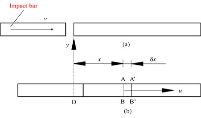
An impact rod impacts a long cylindrical bar at speed , producing a stress wave that propagates from left to right (Fig. 1). During a period , the stress wave propagates in the right rod from displacement (cross-section AB) to displacement (cross-section A'B'). The strain and inertia along the direction Oy are ignored, the rod is assumed to undergo elastic deformation, the Newton’s second law is applied to two adjacent sections AB and A'B', the tension force is set to be positive, and the pressure force is negative [19-20]. The one-dimensional wave differential equations are then obtained as:
where is the direction, m; is time, s; is the wave speed, m/s; is the displacement of the rod particle along the direction at time , m; and and are waves propagating respectively in the and directions at speed at time , m. These waveforms do not change with time and spread. If there is only a wave propagating in the direction, then 0.
The wave speed is:
where is the elastic modulus of the bar material, Pa, and is the density of the bar material, g/mm3.
Fig. 1Wave propagation: a) before impact, b) after impact
For the waves propagating in the direction, the speed and stress of particles are:
where is the speed of waves propagating in the direction, m/s; is the stress of waves propagating in the direction, MPa; and is the displacement, m.
For the waves propagating in the direction, the speed and stress of particles are:
where is the speed of waves propagating in the direction, m/s, and is stress of waves propagating in the direction, MPa.
2.2. Reflection and transmission of waves
At an interface where the density, elastic modulus or sectional area of the medium changes significantly, waves will be reflected and transmitted [19, 20].
Assuming that elastic waves propagate from medium to medium with different wave impedance (, ), the propagation direction is perpendicular to the interface. When the disturbances of the incident stress wave reach the interface, there will be disturbances in both medium A and medium i.e., reflected-wave disturbances spread to medium and transmitted-wave disturbances spread to medium B.
The stress and speed of an incident wave are respectively denoted as , MPa and , m/s; the stress and speed of a reflected wave are respectively denoted as , MPa and , m/s; and the stress and speed of a transmitted wave are respectively denoted as , MPa and , m/s. Stress and speed are related according to the following equations:
where is the reflection coefficient; and is the transmission coefficient:
where:
Here is the ratio of the wave impedances of the two mediums; is the density of medium , g/mm3; is the density of medium , g/mm3; is the wave speed of medium , m/s; is the wave speed of medium , m/s; is the elastic modulus of medium , Pa; and is the elastic modulus of medium , Pa.
When the cross-section of medium is and that of medium is , the reflection coefficient and transmission coefficient are:
where is the cross-section of medium , mm2, and is the cross-section of medium , mm2.
The expressions in Eqs. (13-14) are substituted into Eqs. (6-7) to get:
If , and . Namely media and are of the same material or the cross-section changes for a single medium. Further, if , then and are both positive; i.e., the reflection wave and transmission wave are both compression waves. If , then is negative and the reflection wave is a tensile wave.
It should be noted that reflection of a stress wave on a free end face is equivalent to setting ; i.e., the second medium is equivalent to a vacuum (), and reflection of a stress wave on a fixed end face is equivalent to writing .
2.3. Impact stress acting on bit matrix
2.3.1. Simplification and hypothesis for piston and bit
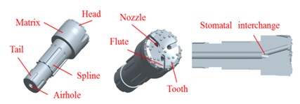
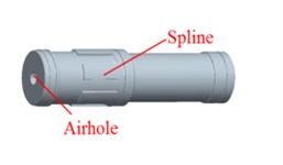
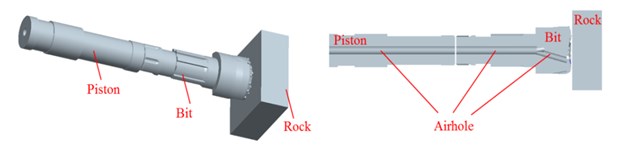
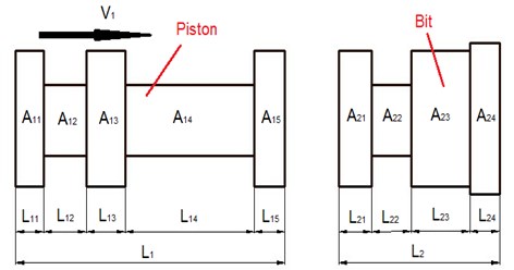
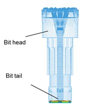
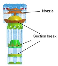
As shown in Fig. 2(a), the drill bit is consisting of airhole, spline, matrix, nozzle and so on. The piston- drill rock model can be expressed as Fig. 2(c). To facilitate the theoretical analysis, the piston and bit are simplified (Fig. 3). is the total length of the piston, mm; is the length of each section of the piston, mm; is the cross-sectional area of each section of the piston, mm; is the total length of the drill, mm; is the length of each section of the bit, mm; and is the cross-sectional area of each section of bit, mm2. The detailed simplification and hypothesis are as follows:
(1) The geometric features of spline, nozzle, flute, tooth and airhole are ignored (Fig. 1);
(2) The material of the piston and bit are the same and isotropic;
(3) The principal impact stress and main reflection impact stress are considered. The aftermath is not considered.
Fig. 2Pistons-drill-rock three-dimensional solid model: a) bit, b) piston, c) pistons-drill-rock model and its inner structure
a)
b)
c)
Fig. 3Piston and bit
2.3.2. Maximum principal impact stress appears in each section of the bit when an impact stress wave propagates from the bit tail to the head
Since the cross-sections of the piston and drill are uneven, there are reflections and transmission phenomena in the dissemination of impact stress waves produced by the piston impacting the bit. The density, elastic modulus and wave speed of piston and bit are same since they are of the same material.
Eqs. (14-15) is used to calculate the coefficients of reflection and transmission at each section interface of the piston and bit. The expressions are given in Tables 1 and 2.
The shock waves propagating in the and directions in the piston are respectively denoted as and . Before impact, the speed of the piston is and the stress of the piston is zero. From Eqs. (3-4) and (5-6), it follows that:
where is the stress of the stress wave propagating within the piston section in the direction, MPa; is the stress of the stress wave propagating within section of the piston in the direction, MPa; is the displacement of the stress wave propagating within the piston section in the direction at speed , m; is the displacement of the stress wave propagating within the piston section in the direction at speed , ; is the speed of the stress wave propagating within the piston section in the direction, m/s; is the speed of the stress wave propagating within the piston section in the direction, m/s; and is speed of the stress wave 1, m/s.
Table 1Reflection coefficient of each section of piston and bit
Reflection | Coefficient | Reflection | Coefficient |
Reflection from interface into section | Reflection from interface into section | ||
Reflection from interface into section | Reflection from interface into section | ||
Reflection from interface into section | Reflection from interface into section | ||
Reflection from interface into section | Reflection from interface into section | ||
Reflection from interface between section and tooth into section | Reflection from rock interface into tooth |
Table 2Transmission coefficient of each section of piston and bit
Transmission | Coefficient | Transmission | Coefficient |
Transmission from interface into section | Transmission from interface into section | ||
Transmission from interface into section | Transmission from interface into section | ||
Transmission from interface into section | Transmission from interface into section | ||
Transmission from interface into section | Transmission from interface into section | ||
Transmission from interface into section | Transmission from interface into section | ||
Transmission from interface into section | Transmission from interface into section | ||
Transmission from interface into section | Transmission from interface into section | ||
Transmission from interface into section | Transmission from interface into section | ||
Transmission from interface into tooth | Transmission from interface into section |
The solution can be obtained as:
where is stress of the stress wave 1, MPa.
When the piston impacts the bit, the largest stress acting on the bit tail section is:
where is the stress of a wave transmitted from interface into section , MPa; is the coefficient of transmission from interface into section (Table 2); is the cross-sectional area of ; is the cross-sectional area of ; and is the cross-sectional area of .
Since there are section mutations (sudden change between two different section areas) between the section of length and section of length when the impact stress wave arriving from the bit tail propagates to interface , there is a separate propagation of right-traveling impact stress waves in section and left-traveling impact stress waves in section ; i.e., there are transmitted waves and reflected waves at interface .
According to Eqs. (7-8), the stress reflected into at interface is:
where is the reflection coefficient of the impact stress wave at interface (Table 1). is stress of a reflected wave from interface into section , MPa.
Because , it follows that , which shows that the reflection wave reflected into the bit tail at interface is a tensile wave; i.e., tensile stress will appear in section of the bit tail.
According to the principle of wave superposition, the total stress in section of the bit tail is:
where is the total stress in section of the bit tail, MPa.
Therefore, the greatest impact stress in section is .
When the impact stress wave arriving from section transmits into section at interface , the impact stress in section is:
where is the stress of a wave transmitted from interface into section , MPa, and is the coefficient of transmission from interface into section .
Similarly, since there are section mutations in the section, when the impact stress wave arriving from section propagates at interface , there is the transmission and reflection of waves.
According to Eqs. (7-8), the reflecting stress entering at interface is:
where is the stress of a wave reflected from interface into section , MPa, and is the reflection coefficient of the impact stress wave at interface (Table 1).
Since , in cross-sectional area, it follows that, which shows that the reflection wave entering section at interface is a compressional wave.
According to the principle of wave superposition, the maximum stress in section of the bit tail is:
where is the maximum stress in section of the bit, MPa; is the stress of a wave reflected from interface into section , MPa.
Similarly, stresses in section are:
where is the stress of a wave transmitted from interface into section , MPa; is the coefficient of transmission from interface into section ; is the stress of a wave reflected from interface into section , MPa; is the coefficient of reflection from interface into section ; is the maximum stress in section of the bit, MPa; and is the coefficient of transmission from interface into section .
Stresses in section are:
where is the stress of a wave transmitted from interface into section , MPa; is the coefficient of transmission from interface into section ; is the stress of a wave reflected from interface into section , MPa; is the maximum stress in section of the bit, MPa; and is the coefficient of reflection from the interface between section and the tooth into section .
2.3.3. Main reflection impact stress appears in each section when impact stress wave propagates from bit head to tail
When the main impact stress wave propagates to the bit head , some of the stress wave is transmitted into a tooth, and the remainder is reflected into . When the tooth impacts rock, part of the stress wave is reflected in the tooth and transmitted into . Therefore, the main reflection stress in the bit head is:
where is the maximum stress of the main reflection stress in bit , MPa; is the coefficient of transmission from interface into section ; is the coefficient of transmission from interface into the tooth; is the coefficient of reflection from the rock interface into the tooth; is the stress of the superposition wave of stress waves 1 and 2, MPa; and is the stress of a reflected superposition wave of stress waves 1 and 2, MPa; is transmission coefficient from interface into section .
Similarly, the main reflection stress in section is:
where is the maximum stress of the main reflection stress in bit , MPa, and is the coefficient of transmission from interface into section .
The main reflection stress in section is:
where is the maximum stress of the main reflection stress in bit , MPa, and is the coefficient of transmission from interface into section .
The main reflection stress in section is:
where is the maximum stress of the main reflection stress in bit , MPa. is transmission coefficient from interface into section .
2.4. Results and discussions
The QL120 air hammer and auxiliary bits (parameters given in Tables 3 and 4) used at the Puguang gas field in China are taken as a calculation example.
Table 3Relevant parameters of piston
Length (mm) | |||||
60 | 110 | 220 | 360 | 92 | |
Diameter (mm) | |||||
207.5 | 191.5 | 207.5 | 177.5 | 187.5 | |
Area (mm2) | |||||
33816.3 | 28802.3 | 33816.3 | 24745 | 27611.7 | |
Elasticity modulus (Pa) | 0.21⋅1012 | ||||
Density (g/mm3) | 7.85⋅10-3 | ||||
Speed (m/s) | 7 | ||||
Table 4Relevant parameters of percussive rotary drill
Length (mm) | |||||
130 | 99 | 301 | 237 | 130 | |
Diameter (mm) | |||||
187.5 | 171 | 208 | 288.6 | 187.5 | |
Area (mm2) | |||||
27611.7 | 22965.8 | 33979.5 | 65415.8 | 27611.7 | |
Modulus of elasticity (Pa) | 0.21⋅1012 | ||||
Density (g/mm3) | 7.85⋅10-3 | ||||
2.4.1. Maximum principal impact stress
From Eqs. (20) and (23), the largest impact stress in section is
where the negative sign represents compressive stress.
According to Eqs. (26), the largest impact stress in section is:
According to Eqs. (27-29), the largest impact stress in section is:
According to Eqs. (30-32), the largest impact stress in section is:
In summary, a change in the size of the bit section provides a strong discontinuity surface for stress wave propagation, which affects both the amplitude of the stress wave (the amplitude increases as the cross-sectional area decreases) and the nature of the reflection wave (tensile stress or compressive stress). When the compression stress wave is reflected from a smaller section into a larger section, the reflection coefficient is positive, and the reflection stress wave is a compressive wave. In contrast, when the compression stress wave is reflected from a larger size section into a smaller section, the reflection coefficient is negative, and the reflection stress wave is a tensile wave. When the reflection stress wave is a tensile wave, tensile stress is generated in the bit and the bit cracks. Under the repeated action of tensile stress, fatigue cracks grow and extend, and finally, the drill fractures. Therefore, the situation that the reflection stress wave is a tensile stress which is studied in the following.
2.4.2. Main reflection impact stress
The main reflection impact stress propagating in the air hammer bit may be compressive stress or tensile stress, depending on the reflection coefficient . According to the discussion in Section 2.3, if the surface of the bit tooth is a free end surface (i.e., poor chip removal leads to sticking or the bit works in cavity rock formations, resulting in poor contact between the tooth and rock and the rock non-breaking by the bit), then the reflection stress is tensile stress when is –1. When the bit tooth surface is fixed (i.e., the bit works normally), is 1 and the reflection stress is compressive stress. Since tensile stress is the main reason for a bit to crack, later in this work, only the situation is considered that reflection stress is tensile stress.
According to Eq. (33), the main reflection impact stress in section is:
According to Eq. (34), the main reflection impact stress in is:
According to Eq. (35), the main reflection impact stress in is:
According to Eq. (36), the main reflection impact stress in is:
Therefore, the total stress in each section of the bit is:
As seen from the above analysis, for a certain bit section, (1) there is only the effect of the main impact stress wave before the reflection wave arrives, and the section is pressed, and (2) the section is under the combined action of the main impact stress wave and main reflection stress wave after the arrival of the reflection wave. When the amplitude of the main impact stress wave is greater than that of the main reflection stress wave, the bit sections (sections , and ) are pressed. In contrast, when the amplitude of the main impact stress wave is less than that of the main reflection stress wave, the bit sections are stretched (i.e., the total stress in section is always positive). Under the repeated effects of tensile stress, fatigue failure easily occurs, which is the root cause for the easy fracture failure of the bit matrix.
2.4.3. Discussions
According to the above mentioned theory analysis and calculation, the propagation law and characteristics of the stress wave in the bit are obtained. The stress of the bit under different conditions can be easily calculated. The bit section mutation is the root cause for the shock of the impact wave and the change in the nature of the wave during propagation. Typically, the maximal amplitude of the stress wave appears in the smallest section , and section is always subjected to tensile stress. However, as previously mentioned in Section 2.3.1, the effects of the principal impact stress and the main reflection impact stress are only considered in the propagation of stress wave. The aftermath is not considered. In addition, the key geometrical characteristics, such as air hole, spline, nozzle, flute, and tooth, are not considered.
Therefore, it is necessary to use the finite element simulation to explore the cause of the bit fracture. These stress amplitudes and the propagation law can be used as reference values of the result of finite element simulation.
3. Finite element simulation of piston-drill-rock interaction
3.1. Fundamental assumption and verification for FE model
3.1.1. Fundamental assumption
There are many factors to influence the FE simulation results. For the convenience of analysis and calculation, the factors which have a little effect on the process of FE simulation are ignored. The detailed assumption is shown in the following.
(1) The materials of the piston and bit and rock are isotropic and constant;
(2) The bit and piston are set to elastomer;
(3) The piston and bit are always coaxial during the impact process;
(4) The end face of piston contacts with the bit tail face completely;
(5) Air quality is ignored. The pressure of fluid column caused by drilling medium is not considered;
(7) The effects of temperature on the materials of piston, bit and rock are not considered.
(8) The rock elements are immediately deleted after failure.
3.1.2. Verification for FE model
Further, to verify the correctness of FE simulation setting, the coaxial collision of two elastic bars is analyzed by theoretical calculation and FE simulation. The materials and section areas of two bars are the same.
As shown in Fig. 4(a), from the view of stress wave theory, the stress amplitude of the bar B can be expressed as equation 49 according to the Eqs. (20) and (21) and Table 2. Let’s set the initial velocity of the bar A to 6, 7, 8, 9 m/s, and then, the stress amplitudes of the bar B under different conditions can be obtained by the Eq. (49):
where is the stress amplitude in the bar B; is the density of bar A; is the elasticity modulus of bar A; is the initial velocity of bar A.
From the view of FE simulation, the above fundamental assumption is adopted. The material parameters are the same with the ones of theoretical analysis. Besides, the bar A and bar B are meshed with hexahedron elements as shown in Fig. 4(b).
Then, given the different initial velocities of bar A, the different wave stress in the rod B can be obtained using the FE simulation. Furthermore, take 8 elements at the different positions of the bar B. The upper and lower stress limits of the 8 elements are obtained, and the stress limits are expressed as the green curves in Fig. 5.
Fig. 4Coaxial collision model of two bars: a) model for theoretical analysis, b) model for FE analysis
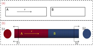
Fig. 5Stress amplitude of bar B by FEA and theoretical calculation
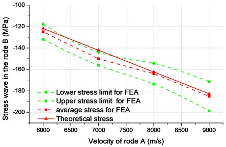
The change trend of the stress wave of FEA is consistent with the stress calculated by equation 70 (the red solid curve in Fig. 5). The mean stress (the red dashed curve in Fig. 5) calculated by FEA is very close to the stress calculated by equation 70, and the average error of FEA compared with the theoretical calculation is less than 5.56 % (Table 5).
Therefore, the simulation model is reliable. The parameters setting of the piston-drill-rock model is same with the coaxial collision model of two elastic bars.
Table 5Reflection coefficients of piston and bit
(t/mm3) | (MPa) | (mm/s) | (MPa) | Average error of FEA | ||
Theoretical calculation | Stress bounds of FEA | Mean stress of FEA | ||||
7.85e-9 | 0.21e6 | 6000 | –121.8 | [–131.9, –118.0] | –125.0 | 2.62 % |
7000 | –142.1 | [–156.0, –144.0] | –150.0 | 5.56 % | ||
8000 | –162.4 | [–173.7, –154.4] | –164.1 | 1.05 % | ||
9000 | –182.7 | [–198.7, –171.5] | –185.1 | 1.31 % | ||
3.2. Geometric model
The main structure of the bit includes splines, nozzles, flutes, teeth, central vents, and matrix (Fig. 1(a)). The main structure of the piston includes splines, vents, and piston body (Fig. 1(b)). The rock is simplified as a cube, and the piston-bit-rock geometry is built (Fig. 1(c)).
3.3. Material conditions
The piston material model is defined as linear elastic/perfectly elastic-plastic material; since the materials of the bit matrix and tooth are harder than rock, they can be defined as linear elastic/perfectly elastic-plastic material [21]. The rock is granite and defined by a plastic strain failure model [22]. Specific parameters are given in Table 6. The density unit is 10-6 kg/m3, the force unit is 106 N, and the pressure unit is 1012 Pa.
Table 6Reflection coefficients of piston and bit
Name | Density | Young modulus | Poisson’s ratio |
Piston | 7.85E-3 | 0.21 | 0.3 |
Bit | 7.85E-3 | 0.21 | 0.3 |
Rock (granite) | 2.6E-3 | 0.4 | 0.2 |
3.4. Meshing
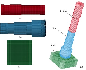
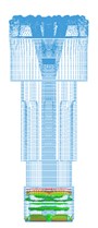
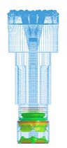
To reduce the computational load while keeping the calculation accuracy, the piston and rock are only meshed with 14004 and 98000 hexahedron elements, respectively, because this paper focuses on the bit. The rock area that is in contact with the bit is meshed densely, and the rock area that is not in contact with the drill is meshed sparsely. The bit is meshed with 413355 hybrid grids, as shown in Fig. 6(b).
The hybrid grid mainly includes the hexahedral and tetrahedral grids. The size of the tetrahedral element changed from 6 mm to 3 mm along the right direction. The left side of the tetrahedral mesh can perfectly be combined with the hexagonal mesh, and the right side of the tetrahedral grid can express the tooth feature very well. The final finite element model is as shown in Fig. 6.
Fig. 6Grid meshing for FEA model: a) piston meshing, b) bit meshing, c) rock meshing, d) piston-drill-rock meshing
3.5. Boundary conditions
According to the field test data for the QL120 air hammer used at the Puguang gas field in China, the speed of the piston is about 6.66 m/s, the rotational speed of the bit is 50 rpm, and the drilling pressure range is 10-50 kN.
In this paper, the rotational speed is set to 50 rpm; the speed of piston is set to 6.5, 7, 7.5 and 8 m/s, and the WOB is set to 0, 10, 30 and 50KN for different situations as shown in Section 3.6. Besides, the simulated rock is considered to be infinitely large, but only a part of the rock can be considered when building the model. Therefore, unlimited non-reflecting boundary conditions are applied to five rock boundary surfaces (not including the rock boundary surface in contact with the bit) [23-24].
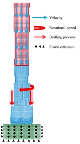
As shown in Fig. 7, the velocity is applied on all piston elements; the drilling pressure is applied on the matrix head face; the rotational speed is applied on all bit elements; the fixed constraints are applied on five rock surfaces (not including the rock surface in contact with the bit).
Fig. 7Boundary conditions setting for simulation model
3.6. Results and discussions
3.6.1. Propagation analysis of impact stress wave in percussive rotary bit
In order to better display the propagation process of an impact stress wave, the WOB is not considered in this section. At this point, the drilling pressure is set to 0 KN, and the velocity of piston is set to 6.5 m/s. Fig. 8 shows the propagation of the main impact stress wave in the drill body. A red color indicates maximum tensile stress (positive value). The analysis results are as follows.
(1) In the process of breaking rock, the energy of the piston propagates from the bit tail to the head in the form of a stress wave. When the stress wave reaches the contact surface between a tooth and rock, some of the energy propagates to the rock (wave transmission), and the rest is reflected (wave reflection) back to the bit at the contact surface and travels from the bit head to the tail.
Fig. 8Propagation process of main impact stress wave in drill body
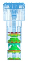
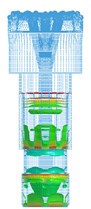
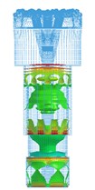
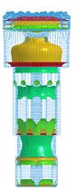
(2) The section mutations (a sudden change between two different section areas) of the bit generate stress wave vibration in the bit body. When an impact stress wave propagates to the bit body, there are many transmissions and reflections at the sectional mutation positions. These results in the stress wave vibration in the bit body and make the bit work under the effect of alternating stress, which is consistent with the theoretical analysis.
(3) The bit matrix bears large tensile stress (of red color), and other parts bear compressive stress, which is consistent with theoretical results. The maximum stress is focused on the bit nozzle interchanges. The stress concentration can more easily induce fatigue fracture under the repeated vibration effect of the stress wave.
3.6.2. Stress analysis of bit matrix
3.6.2.1. Stress analysis of bit matrix for same drill pressure and piston speed
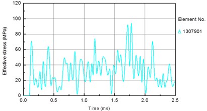
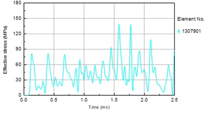
In this section, the drill pressure is set to 10 KN, and the piston speed is set to 7 m/s. The other parameters are set as shown in the Section 3.5. To compare the stress conditions of each section of the bit matrix, an element is considered for each section of the external and internal parts of the bit. Fig. 9 shows the selected element for each section, and Fig. 10 shows the time histories of the stresses of the external and internal elements of the bit body. The following results are obtained from Figs. 9 and 10.
Fig. 9External and internal unit number of bit body: a) external unit, b) internal unit
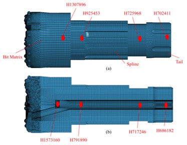
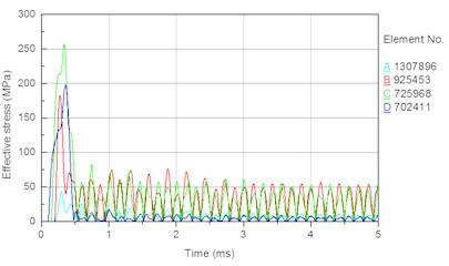
Fig. 10Stress time history of external and internal unit of bit body: a) external unit, b) internal unit
a)
b)
(1) In Fig. 10(a), the stress peaks earliest for the element corresponding to the bit tail (element ), then the elements corresponding to the smaller diameter around the bit tail (element ) and the spline (element ), at finally the element corresponding to the bit matrix (element ). Because the impact stress wave and the maximum stress both propagate from the bit tail to the head, the result is consistent with the propagation characteristic of the impact stress wave in the bit body.
(2) In Fig. 10(a), the peak stress in each element decreases in the order .
According to the theoretical analysis, when a stress wave propagates from a small section to a large section, the amplitude of the transmission stress wave is less than that of the incident stress wave (Fig. 3); i.e., the area ratios and imply the peak stresses and . Therefore, .
When a stress wave propagates from a large section to a small section, the amplitude of the transmission stress wave is greater than that of the incident wave stress; i.e., and .
However, energy of the incident stress wave is lost during the propagation; therefore, .
In summary, the order of the magnitude of peak stress in the different section elements is , and the simulation result is thus consistent with the theoretical result.
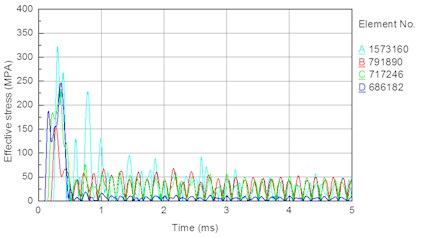
(3) In Fig. 10(a) and 7(b), during the propagation of the impact stress wave, the stress in each element fluctuates frequently, and the fluctuation amplitudes of the different sections are not the same. This is because when the stress wave propagates in the bit body, the bit is under the long-term effect of alternating stress caused by the superposition of transmission and reflection stress waves. The repeated alternating stress will readily lead to fatigue failure of the bit.
(4) In Fig. 10(b), the peak stress and average stress are both largest at stomatal interchanges (Fig. 1(a)) of the bit matrix. A high stress concentration and long-term effect of alternating stress can readily lead to fatigue fracture at stomatal interchanges of the bit matrix. The analysis of bit failures in the field shows that fracturing of the bit body often occurs at the interchanges. Therefore, the simulation result is consistent with the failure of bits used in the field, demonstrating the correctness and rationality of the simulation.
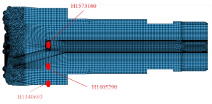
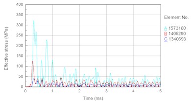
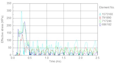
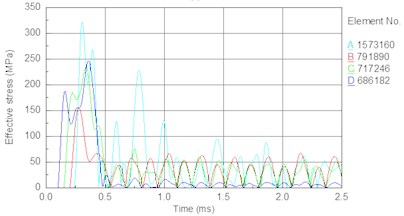
To further analyze the force condition of the bit matrix, elements are taken separately from the external part to the internal part of the bit matrix, as shown in Fig. 11(a). Fig. 11(b) shows the stress time histories for these external and internal elements of the bit matrix. The following results are obtained from Figs. 11(a) and 11(b). The magnitudes of peak stress decrease in order from the internal element to the external element. The peak stress of the internal element (element No. H1573160) is 322 MPa, and that of the external element (element No. H1340693) is about 40 MPa, which shows that there is a high stress concentration at stomatal interchanges. Under the effect of high stress, local stresses will increase suddenly, the formation and extension of cracking will be exacerbated, and the fatigue life of the bit will decrease; thus, bit fracture will ultimately occur. Therefore, in a future design, it is important to improve the structure to decrease the stress concentration and probability of the fracture failure of the bit matrix.
Fig. 11External and internal unit of bit matrix and stress time history: a) external and internal unit of bit matrix, b) stress time history
a)
b)
3.6.2.2. Stress analysis of bit matrix for different drill pressures and same piston speed
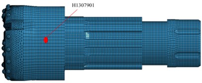
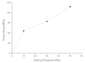
In this section, the piston speed is set to 7 m/s, the drill pressure is set as follows. To facilitate the analysis, an element on the bit matrix is taken (Fig. 12(a)). Fig. 13 shows the stress time history of the bit matrix unit under different drilling pressures. Fig. 12(b) shows the relationship between the drilling pressure and peak stress in the element. It is seen that the stress in the drill matrix element increases with increasing drilling pressure. The peak stress is 66 MPa when the drilling pressure is 10 kN, 94 MPa when the drilling pressure is 30 kN, and 138 MPa when the drilling pressure is 50 kN.
Fig. 12Bit matrix unit and relationship between drilling pressure and unit peak stress of bit matrix: a) bit matrix unit, b) relationship between drilling pressure and unit peak stress
a)
b)
Fig. 13Stress time history of bit matrix unit under different drilling pressure: a) 10 KN, b) 30 KN, c) 50 KN

a)
b)
c)
In percussive rotary drilling, the action of drilling pressure ensures that the bit compresses the rock tightly to break the rock and prevent otherwise from a poor contact between the bit and the rock affecting the stress wave propagation under the action of an impact reaction force and reducing the efficiency of rock breaking. It is clear that, when a bit drills through hard rock formations, with an increase in drilling pressure, wear of the bit body and tooth is not only increased but also the matrix stress is increased. Additionally, there is a high stress concentration at stomatal interchanges, and local stresses will thus increase to exacerbate the formation and extension of the crack, leading to bit fracture.
Therefore, in the drilling process, the high breaking efficiency should not be pursued to increase the drilling pressure. The drilling pressure must be low enough to ensure sufficient service life of the bit but high enough to ensure adequate contact between the bit tooth and rock. Therefore, it is important that a proper drilling pressure be chosen according to the specific geological situation to prevent from fracture of the bit matrix.
3.6.2.3. Stress analysis of bit matrix for same drill pressure and different piston speeds
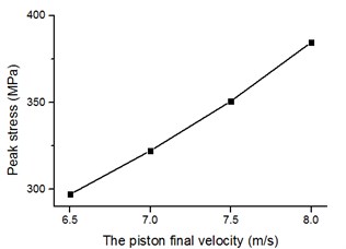
In this section, the drill pressure is set to 10 KN, and the piston speed is set as follows. Fig. 14 shows the stress time history of internal elements of the bit body (as indicated in Fig. 9) for different piston speeds. Fig. 15 shows the relationship between the piston speed and peak stress in an element of the bit matrix. The following results are obtained from the figures. With an increase in piston speed (impact energy), the magnitude of peak stress increases. Table 7 shows that the rate of increase in the bit matrix’s (element A) peak stress is the largest (25, 28, 34 MPa), revealing that an increase in piston speed leads to too much stress in the matrix; the high stress easily leads to fatigue failure of the bit and especially the matrix under the action of the repeated alternating stress.
Table 7Reflection coefficients of piston and bit
Piston speed (m/s) | 6.5 | 7 | 7.5 | 8 | |
Element stress (MPa) | A | 297 | 322 | 350 | 384 |
B | 142 | 155 | 170 | 190 | |
C | 219 | 234 | 260 | 287 | |
D | 227 | 246 | 269 | 295 | |
Increase in stress (MPa) | A | 25 | 28 | 34 | |
B | 13 | 15 | 20 | ||
C | 15 | 26 | 27 | ||
D | 19 | 23 | 26 | ||
Fig. 14Stress time history of bit body internal unit under different piston speed: a) 6.5 m/s, b) 7 m/s, c) 7.5 m/s, d) 8 m/s
a)
b)
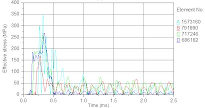
c)
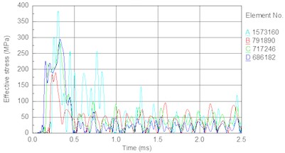
d)
Fig. 15Relationship between piston speed and unit peak stress of bit matrix
It is thus important in the drilling process to choose proper air pressure to get a proper piston speed. It is not wise to pursue a high drilling speed, because early fracture failure resulting from a large drilling force will reduce the drilling efficiency and increase drilling costs.
4. Discussions and future research
In this paper, the theory analysis and FEA simulation is used to research the fracture mechanism of air percussive rotary bit matrix. The propagation law of the stress wave and the underlying causes of the law can be revealed by the theory analysis. Meanwhile, the stress wave status for the special position such as the root of the spline and the air hole of the matrix can be analyzed by the FEA. At last, the stress wave bit matrix propagation features are obtained. The main influencing factor for the fracture failure of the bit matrix is also obtained.
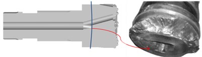
Typically, the bit matrix is under tensile stress loading, and the peak stress at the stomatal interchanges is high during the drilling process. This will lead to the stomatal interchange appearing on the crack damage, and further leading to the early fatigue fracture of the bit. This result is consistent with the failure of the bits used in the field, as shown in Fig. 16, thereby demonstrating the correctness and rationality of the FEA. In addition, the stress amplitude of the bit matrix increases and the fatigue life of the bit decreases with increasing drilling pressure and piston speed. Therefore, it is important to adopt reasonable drilling technology parameters.
Fig. 16Fracture at stomatal interchanges in drilling filed
In order to reduce the peak stress at stomatal interchanges and extend the service life of the bit, we put forward some suggestions and several future researches as follows.
(a) Research the bit structure optimization.
Make an optimization of bit structure, especially at the stomatal interchanges of the bit matrix, in order to ease the phenomenon of high stress concentration, avoid the early fracture of bit, extend the bit life and reduce the drilling cost.
(b) Improve the processing quality of bit.
The airhole is in the bit body. Thus, the airhole is difficult to be processed. Process quality is also hard to be guaranteed, especially at the stomatal interchanges. Some manufacturing deficiencies such as deep tool marks and high surface roughness will happen. These deficiencies will become the root for generating crack in the bit matrix. Therefore, this paper advises that the bit should be processed in the factories which have sound processing equipment and heat processing technology, and have an experience in resembling bit processing.
(c) Choose the available drilling process parameters.
When drilling hard formation, small weight on bit (WOB) is recommended, while the low WOB must be based on the sufficient contact between the bit and rock. For the determination of air pressure in the airhole of the bit, the rock breaking efficiency, and the service life of the bit should be considered. The high air pressure can increase the impact energy of the piston; make the bit to break rock with a high power. However, a high pressure may lead to an early failure of bit matrix, low drilling efficiency and high drilling cost.
5. Conclusions
This paper mainly analyzes matrix failure mechanism and effects of drilling parameters on bit. The authors believe the failure mechanism makes a great guiding significance to the improvement of bit performance and reduction of matrix failure for air percussive rotary drilling. For instance, to improve the performance of bit, the phenomenon of large peak stress, such as at the stomatal interchanges, should be avoided in the stage of bit design. Meanwhile, the impact energy of piston should be also considered in this stage. For another example, to avoid or reduce the failure of bit matrix, WOB should be controlled in a reasonable range according to different formations in field application. In addition, our study suggests that the stress peak calculated by FE simulation can be as an essential criterion for the design of air percussive rotary bit. Furthermore, the novel method of stress wave analysis based on FE simulation in Section 3 can be extended and applied on structural design for other types of percussion drilling tools. The main conclusions of this paper are shown in the follows:
1) Bit section mutation (a sudden change between two different section areas) is the root cause for the shock of the impact wave and the change in nature of the wave during propagation.
2) The tensile wave is the root cause for bit matrix fracture. The fracture is the most serious at stomatal interchanges.
3) In the propagation of an impact stress wave, stress is concentrated at stomatal interchanges. Stomatal interchanges are thus the weakest parts of a bit. This result is consistent with fractures of bits in the field.
4) The stress amplitude of the bit matrix increases, and the fatigue life of the bit decreases with an increase in drilling pressure. Therefore, in the drilling process, the drilling pressure must be sufficiently low to preserve the service life of the bit; however, drilling pressure that is too low will lead to inadequate contact between the bit tooth and rock and reduce the breaking efficiency. It is important to choose proper drilling pressure according to the specific geological situation to prevent from the bit matrix fracture.
5) With an increase in piston speed (impact energy), the magnitude of peak stress increases, and an increase in peak stress of the matrix leads to an early fatigue failure. In the drilling process, therefore, it is important to choose proper air pressure so that the piston speed is sufficiently low to prevent from the bit matrix fracture.
6) Rational design of the sectional structure parameters of the bit will ensure that the bit withstands the effects of the compression wave and will reduce the appearance of a tensile wave, thus reducing a fatigue failure of the bit matrix. Furthermore, proper selection of the operational parameters (such as drilling pressure and air pressure) is also fundamentally important, in terms of reducing the bit matrix fracture and extending the bit life.
7) The structure and material are two important factors that affect the bit matrix fracture and cannot be ignored. In this paper, the cause of the bit matrix fracture is studied from the view of structure. The effect mechanism of the stress wave acting on bit matrix fracture is investigated revealing the location of large stress and the relationship between the fracture and the structural design parameters. We will consider carrying out the structure optimization based on the effect of different structure parameters on the peak values of stress wave. The effect of the different model on the crack damage speed from the material view will be also carried out in the next step of our work.
References
-
Fan Y. T., Huang Z. Q., Gao D. L., Li Q. Experimental study of Al2O3/WC–Co nanocomposite based on failure analysis of hammer bit. Engineering Failure Analysis, Vol. 18, 2011, p. 1351-1358.
-
John M., Michael S. Air hammers cut Barnett shale drilling time in half. World Oil, Vol. 9, 2004, p. 71-72.
-
Kembaiyan K. T., Keshavan K. Combating severe fluid erosion and corrosion of drill bits using thermal spray coating. Wear, Vols. 186-187, 1995, p. 487-492.
-
Deshpande P. K., Lin R. Y. Wear resistance of WC particle reinforced copper matrix composites and the effect of porosity. Materials Science and Engineering: A, Vol. 418, 2006, p. 137-145.
-
Reyes M., Neville A. Degradation mechanisms of Co-based alloy and WC metal-matrix composites for drilling tools offshore. Wear, Vol. 255, 2003, p. 1143-1156.
-
Zhang J., Yu W. Application of air drilling technology in Puguang Gas Field. Drilling Process, Vol. 6, 2006, p. 8-10.
-
Yina Y., Bantiwalub E. A. Optimizational analysis for experimental study of iron-based diamond drill bit matrix formula. Procedia Engineering, Vol. 16, 2011, p. 486-492.
-
Honga E., Kaplin B., You T., Suh M., Kim Y., Choe H. Tribological properties of copper alloy-based composites reinforced with tungsten carbide particles. Wear, Vol. 9, Issue 10, 2011, p. 591-597.
-
Tan S., Yang Y. Study on mechanical performance of iron based matrix for hot pressed diamond bit. Diamond and Abrasives Engineering. Vol. 2, 2009, p. 49-52.
-
Loshak M. G., Alexandrova L. I. Rise in efficiency of use of cemented carbides as matrix of diamond-containing studs of rock destruction tool. International Journal of Refractory Metals and Hard Materials, Vol. 1, 2001, p. 5-9.
-
Liu G. Parameterized mockup design of PDC bits based on Pro/E. Procedia Earth and Planetary Science, Vol. 3, 2011, p. 435-439.
-
Zhou Y., Huang Z., Zhang F., Jing S., Chen Z., Ma Y., et al. Experimental study of wc-co cemented carbide air impact rotary drill teeth based on failure analysis. Engineering Failure Analysis, Vol. 36, Issue 36, 2014, p. 186-198.
-
Momeni S., Moseley S., Ante M., Allaart J., Hilti A. G. The wear of wc-co drill bits during rotary-percussive drilling of reinforced concrete. International Journal of Refractory Metals and Hard Materials, 2016.
-
Beste U., Jacobson S. A new view of the deterioration and wear of wc/co cemented carbide rock drill buttons. Wear, Vol. 264, Issue 11, 2008, p. 1129-1141.
-
Maekawa I. The influence of stress wave on the impact fracture strength of cracked member. International Journal of Impact Engineering, Vol. 32, Issue 1, 2005, p. 351-357.
-
Elı́as D. A., Chiang L. E. Dynamic analysis of impact tools by using a method based on stress wave propagation and impulse-momentum principle. Journal of Mechanical Design, Vol. 125, Issue 1, 2003, p. 131-142.
-
Zheng S., Wang D., Zheng R., Wang X. Research on the detection system for impact energy of pneumatic drill based on stress wave technique. IEEE International Conference on Electronic Measurement and Instruments, Vol. 3, 2015, p. 1415-1419.
-
Carcione J. M., Poletto F. Simulation of stress waves in attenuating drill strings, including piezoelectric sources and sensors. Journal of the Acoustical Society of America, Vol. 108, Issue 1, 2000, p. 53-64.
-
Guo W. Stress Wave Brief Tutorial. Northwestern Polytechnical University Press, Xian, China, 2007.
-
Ma X. Impact Dynamics. Institute of Technology Press, Beijing, China, 1992.
-
Fan Y. T., Huang Z. Q., Gao D. L., Li Q., Zhu H. Y. Study on mechanism of impactor-bit-rock interaction using 3D FEM analysis. 2nd International Conference on Manufacturing Science and Engineering, ICMSE, 2011, p. 2280-2284.
-
Franca L. F. P. Bit-rock interaction model for rotary-percussive drilling. International Journal of Rock Mechanics and Mining Sciences, Vol. 5, 2011, p. 827-835.
-
Chiang L. E., Elias D. A. Modeling impact in down-the-hole rock drilling. International Journal of Rock Mechanics and Mining Sciences, Vol. 4, 2000, p. 599-613.
-
Chianga L. E., Elíasb D. A. 3D FEM methodology for simulating the impact in rock-drilling hammers. International Journal of Rock Mechanics and Mining Sciences, Vol. 5, 2008, p. 701-711.
About this article

