Abstract
In this paper, the dynamic response characteristics of a common double shear lap joint structure with viscoelastic layer are investigated. Firstly, an analytical model is established in shear vibration based on phenomenological model. The fourth order Runge-Kutta method is employed to calculate the harmonic response, where the effect of Coulomb friction and excitation levels on system are presented. Secondly, a new nonlinear finite element model for the bolted joint structure with viscoelastic layer is developed. The simulation results show good agreement with the corresponding experimental results. Finally, the proposed harmonic excitation experiments with laser vibrometer in tangential direction are carried out to investigate the nonlinear behaviors of system, as well as the influence of bolt preload and viscoelastic material on dynamic characteristics of the bolted joint beam. The results show that the viscoelastic layer help reduce vibration at certain extent, especially in the high frequency region of vibration, and some peak frequencies of system can be changed through the viscoelastic layer.
1. Introduction
The nonlinear behavior of the bolted joint structure has long been studied in the context of engineering machinery. Bolted joint characteristics are of great significance because of its influence in structural vibration and play a decisive role in the overall dynamics. Usually, structural joints are also considered to be a source of energy dissipation between interfaces. Reducing structural vibrations is a very important challenging working for many designers. In some applications, the vibration can be controlled by avoiding exciting the structure at its natural frequencies, or increasing the damping in the structure under the premise of avoiding resonance.
Noise and vibration are often limiting factors in the performance of many industrial machines. Viscoelastic damping has been widely used in the control of vibration and noise in industrial applications, large civil engineering structures as well as aerospace industry [1-3]. The behavior of viscoelastic materials is characterized with strain and strain rate and temperature dependence. The works of Park and Rouleau [4, 5] represent the use of viscoelastic materials and nonlinear characteristics. Also, some related studies about viscoelastic materials have been carried out by other researchers, which are useful for future structural modeling work. Moreover, it needs to be pointed out that the friction between bolt interfaces partially contribute to reduce the level of structural vibration [6, 7]. However, for the sandwich bolted joint structure with viscoelastic material, most studies have been focused on the development and research of viscoelastic materials itself, but more detailed descriptions about modeling and nonlinear behavior are still inadequate.
The double shear lap joint structure with bolts is a kind of common connection substructure in aviation and engineering machinery, with considerable stability. To solve the nonlinear dynamic problem produced by bolted joint interface, different modeling approaches can be found in the literatures. Both phenomenological and constitutive models have been applied extensively in the previous researches [6-8]. Nowadays, the finite element method (FEM) also presents more satisfactory modeling results for bolted joint properties, as reported by previous literatures [9-11]. However, due to the viscoelastic material increasing the complexity of the interface characteristics, the modeling study for the bolted joint structure with viscoelastic layer (as can be seen in Fig. 1), is rarely introduced, especially when the system is under varying loading conditions.
The bolted joint interface introduces both linear and nonlinear dynamics simultaneously, which is a challenge for experiment precision and design. At present, modal testing [12, 13] and impulse tests, etc. have always been widely used in reports. Although there have been already some experimental studies on bolted joint structure, less reports have been found on the excitation experiment of tangential direction for the sandwich structure with viscoelastic material. Motivated by above, an experimental investigation on the nonlinear dynamic response under shear vibration is conducted in the current study.
Even though various nonlinear models for the connected structure with bolts have been applied in the dynamic researches, analytical modeling approach in the bolted joint structure with viscoelastic layer still needs to be further developed due to the complexity of interface. In addition, the shear excitation may cause additional deflection of vibration, which results in the changes of overall dynamic performance, or eventually induce bolt relaxation and fatigue fracture. Up to now, there have been few published studies discussing modeling method of bolted joint interface with viscoelastic layer to capture system's dynamic characteristics under harmonic shear excitation. Therefore, the purpose of the present work is to develop a nonlinear dynamic model of bolted joint structure and investigate the influence of nonlinear factors of bolted joint interface with viscoelastic layer on system dynamic characteristics in harmonic shear excitation. To this end, an analytical model for double shear lap joint structure with viscoelastic layer is first proposed based on phenomenological model, and the dynamic responses of system under various Coulomb friction and excitation levels are analyzed. Furthermore, a new FE modeling technique with nonlinear stiffness is developed based on contact algorithm. Finally, the relative harmonic experiments with laser vibrometer are investigated in detail, and also show good agreement with the simulation results.
2. Mathematical model
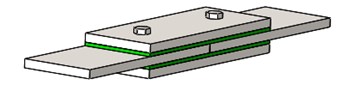
To evaluate the dynamic response characteristics of bolted joint structure with viscoelastic layer, a detailed analytical modeling approach is developed in this section. Fig. 1 shows the 3D model diagram of the connected structure, which consists of the four low-carbon steel plates and M12 bolts. The viscoelastic layer is sandwiched in the double shear lap joint region of combined plates, and the lap region locates in the center part. The double shear structure with bolts is a kind of common component in engineering equipment, which is also widely studied.
Fig. 1The double shear lap joint structure with viscoelastic layers
2.1. Simple model of viscoelastic layer in bolted joint beam
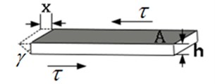
The viscoelastic layer has been widely used in various mechanical structures and has appreciable influence on dynamic characteristics of connection structures, which is mainly reflected in nonlinear stiffness and damping of interface. The viscoelastic layer model sandwiched in bolted joint beam is built in the shear direction, as shown in Fig. 2. The harmonic shear force acting on the material element produces a shear stress in the layer. The stress can be expressed as:
where is the shear modulus and is the shear angle, is the transverse thickness and is the corresponding displacement.
The shear stress can be also given by:
where is the harmonic shear force, , and is the shear area of contact.
Substituting Eq. (2) into Eq. (1) gives:
Fig. 2The schematic of viscoelastic layer model
2.2. Viscoelastic material characteristics
When viscoelastic material is used in the bolted joint structure, its elastic and viscous properties will play a critical role in nonlinear vibration. The dynamic response characteristics are changed with different situations, such as temperature, frequency, loss factor, and there are various phase differences between the excitation force and displacement response. Normally, a complex modulus is chosen to describe the features of viscoelastic material. Many researchers have introduced different viscoelastic materials into structural dynamic analysis [14]. Moreover, the shear modulus and the loss factor have dependence on frequency and temperature, the initial variable values of system in general are based on the indoor temperature 25 °C, which is also applicable to experimental environment.
Through the complex modulus , the Eq. (3) takes the form:
Thus, the harmonic displacement can be obtained as , where and are respectively given by Eqs. (5) and (6) respectively:
2.3. Dynamics model
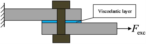
For bolted joint structure, the preload provides the corresponding initial friction force between contact surfaces. Thus, the global relation between the tangential force and the relative displacement in the frictional interface can be described based on phenomenological model. At the meantime, in order to analyze and highlight the characteristics of the bolted joint interface with viscoelastic layer, the simplified structure in Fig. 1 is reduced to a 4 degree of freedom (DOF) model in the tangential direction or loaded harmonic shear force direction, as shown in Fig. 3. Also, the refinement process contributes to judge different motion states between contact surfaces and analyze dynamic response. This simplified discrete model respectively consists of mass and , representing the upper beam’s mass, and mass and representing the lower beam's mass. The viscoelastic layer is represented by a nonlinear spring-dashpot model. The expression of nonlinear stiffness is determined by the properties of viscoelastic material itself, which can be observed in relevant experimental results [15].
Fig. 3Four degree of freedom(DOF) nonlinear model
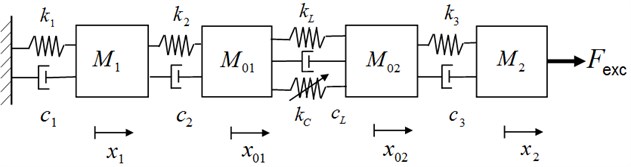
The equation governing the dynamics of the structure are given by:
where and are the displacement, dots represent derivatives with respect to time, ( 1, 2, 3) and are the viscous damping coefficient, and are the stiffness parameter for the upper beam and for the lower beam. The contact between the viscoelastic layer and two beams is ensured by a combined stiffness and , which represent respectively linear spring stiffness and cubic spring stiffness. The cubic stiffness term has little effect on small deflections in linear behavior, and the deflection amount of cubic spring will cause more nonlinearity in the case of low preload or high excitation amplitude. is assumed to be the sum of shear force of viscoelastic material layer in bolted joint and Coulomb friction , where changes with the time and displacement, , is friction coefficient, is the normal force.
To judge the effect of viscoelastic layer on dynamic characteristics of bolted joint interface under harmonic excitation, we first define a mass ratio :
Substituting Eq. (11) into Eq. (9), and combining Eq. (8) gives:
where:
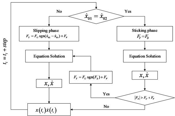
Considering the interaction between interlayer and plate in harmonic shear excitation, two different motion phases are respectively defined. First, for sticking phase, and , where Second, for slipping phase, where . Additionally, due to the variability of characteristics of viscoelastic material, if the viscoelastic material reaches its limit state in nonlinear vibration, such as or the temperature goes beyond the normal range of itself, it would get into the third phase, called 'failure phase' or equivalent to no existence in the interlayer of structure, where , indicating that there is only Coulomb friction between bolted joint interfaces. The flowchart of calculation for different motion states is shown in Fig. 4.
Fig. 4The algorithm flowchart
2.4. Numerical results and analysis
For bolted joint structure, the variation in preload brings about the change of related parameters of joint interface. In this part, due to the existence of viscoelastic layer sandwiched in bolted joint interface, in order to investigate the effects of Coulomb friction and excitation level on system under harmonic response, the corresponding dynamical behaviors are described. Based on the fourth order Runge-Kutta method, the coupled differential motion Eqs. (7)-(10) are solved in the MATLAB software for the four-DOF nonlinear system. The storage modulus and loss factor of viscoelastic material are respectively 4.15e6 Pa and 0.683, which are obtained from the literature [14]. The parameter values of the systems are listed in Table 1.
Fig. 5 shows the frequency response curves at the point of for various Coulomb frictions.
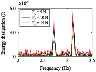
It may be noticed that the amplitude increases with the increasing of Coulomb friction. The frequencies in the vicinity of 2.7 Hz and 3.1 Hz have some small changes, which indicates that the nonlinearity of the system is visible. Fig. 6 represents that the energy dissipation increases when the tightening force is increased.
Table 1Simulation parameters of the numerical system
Parameter | Value |
(kg) | 1.0 |
(kg) | 0.1 |
(Ns/m) | 0.02 |
(N/m) | 1e7 |
(N/m) | 1e7 |
(N/m3) | 1e5 |
(Ns/m) | 0.01 |
(mm) | 2.0 |
(m2) | 1.245 |
(N) | 100, 150, 200 |
Fig. 5The comparison of frequency response curves in various Coulomb frictions
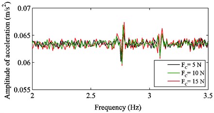
Fig. 6The spectrum of energy dissipation in various Coulomb frictions
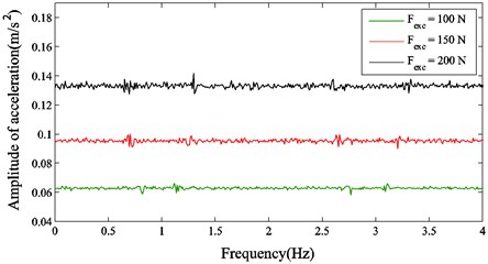
For the sandwich viscoelastic material, actually it plays a role in reducing the vibration of the global joint structure. Thus, when the amplitude of acceleration and the energy dissipation caused by Coulomb friction are controlled by the preload, it is likely that the stiffness of bolted joint interface and the total dissipated energy of system would be changed. In addition, the amplitude-frequency curves at the point of in various harmonic excitation levels are shown in Fig. 7. It can be seen that as the excitation level increases, the magnitude of amplitudes at several main frequencies are also increased. The amplitudes of acceleration at 0.8 Hz and 2.8 Hz shift left gradually and their corresponding frequencies decrease, inversely the amplitudes of acceleration at 1.5 Hz and 3.1 Hz shift right so that their corresponding frequencies increase. This indicates that the nonlinear effects in different excitation levels are very obvious. Moreover, the viscoelastic material sandwiched in structure can exhibit different characteristics in various external excitations, such as varying storage modulus, damping modulus and loss factor. The nonlinearity of material itself has much influence on dynamic behavior of the whole system, and the stiffness of bolted joint interface is related to the stiffness properties of viscoelastic material, which illustrates that design for viscoelastic layer at a great extent can be helpful to reduce vibration and control the energy dissipation in nonlinear system.
Fig. 7The comparison of frequency response curves in various harmonic shear excitation
3. FEM modeling of the bolted joint beam with viscoelastic layer
In order to investigate the application of nonlinear stiffness in finite element modeling and dynamic analysis of the connection structure, a 3D finite element model (from Fig. 1) is developed in ABAQUS, as shown in Fig. 8(a), which totally consists of 66720 elements and 90322 nodes. Model dimensions are shown in Fig. 8(b).
Fig. 8Finite element model

a) Global model
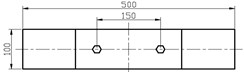
b) Dimension graph

c) Local mesh graph
The rectangular steel plate has a thickness of 5 mm, thus the thickness of each plate is represented by double rows of finite elements. The interface considers both the preload and the frictional effects. Thus, the normal stiffness and shear stiffness are simultaneously taken into account in our finite element analysis. For the pre-stressed state of bolted joint, the contact nonlinearity relationship is built by using surface-to-surface contact and the master-slave algorithm. The main contact pairs are defined as the annular regions, as shown in Fig. 8(b). Its outer radius is about 1.8 times the radius of bolt hole, due to stress distribution area in linear system basically concentrating in this range. Also, in order to obtain reliable numerical results, different mesh densities are assigned respectively on annular regions and other regions on the plates.
The equivalent normal load applied on the bolt and nut can be calculated by the following equation [16]:
where is the selected torque; is the dimensionless nut factor, which is approximately equal to 0.2 for all cases; is the nominal diameter of the bolt.
In this numerical model, the calculations of multiple load steps are done, including the bolt preload as the first analysis step and the subsequent harmonic load. Through the application of the Lagrange’s approach, the general form of equation for the combination beam system with viscoelastic material is given by:
where is the vector of generalized displacements, is the mass matrix, is the damping matrix, is the linear stiffness matrix, is the cubic stiffness matrix. The element type C3D8R with dynamic explicit reduced integration is used to mesh the whole model. The normal behavior in contact is considered to be hard contact. The material properties include Elastic modulus 2.1×10⁵ MPa, Poisson ratio and density 7.85×10³ kg/m3. Based on the contact algorithm, the nonlinear stiffness matrix is added into the computational model in harmonic shear excitation.
4. Experimental investigations and discussion
In this part, dynamic experimental studies based on the harmonic shear excitation are carried out to investigate the nonlinear behavior and analyze the effects of preload and viscoelastic layer material on dynamic characteristics of the double shear lap joint structure. Moreover, the experimental results are compared with the simulation datum.
4.1. Experimental scheme
In our investigation, the experimental system is set up, shown in Fig. 9.
Fig. 9Double shear lap beam experimental setup

a) Position diagram of laser testing and vibration exciter
b) Laser projection in the lens
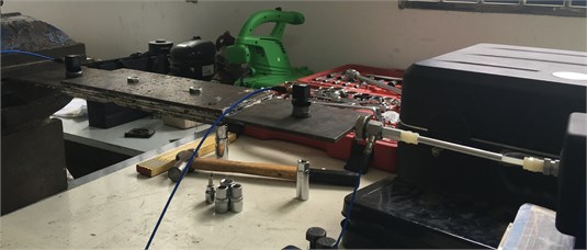
c) Acceleration sensors location
Two tri-axial sensors are respectively arranged near the right and left ends of double shear lap joint structure with viscoelastic layer. The chosen sensors are PCB Model 356B08 with a 10 mV/m/s2 sensitivity. The data acquisition and analysis system used in this study is international SO Analyzer with 8 channel (VXI Mainframe rack unit, Agilent E8491B). The vibration exciter is placed on the right cross section of the plate. The laser vibrometer is the VibroMap 1000 TV-holography system (Germany Optonor) with high sensitivity, which is a laser based system for full field and non-contact vibration and static deflection measurements. For the best possible results, the system is isolated from vibration source and noise, and laser irradiates the right cross sections of the upper and middle plates in a reasonable measurement distance. Silicone rubber is used as experimental viscoelastic material. The bolts are tightened to a predefined torque with a torque wrench. During test, bolt preload levels are adjusted in turn to be 4 N·m, 8 N·m, 12 N·m. The coherence function should be kept well in dynamic testing.
4.2. Experiment results
Fig. 10 shows the frequency response functions (FRF) between the acceleration of mass on left end and the input excitation for various bolt torques. It can be seen that the peak frequency and amplitude change significantly with the increasing of bolt preload, especially in the vicinity of 220 Hz and 460 Hz. The nonlinear effect is very obvious due to the change of interface parameters. Also, the amplitude variation in high frequency region is relatively smaller than that in low frequency region when the torque is increased. These phenomena indicate that the viscoelastic layer to some extent is more suitable for the vibration reduction of high frequency region for the bolted joint structure, compared with the low frequency region, and meanwhile has potentially possibility to help avoid some critical frequency of the structure. The simulation result also shows good agreement with the experimental one, reflecting accurately the dynamic behaviors of system.
Fig. 10Comparison of frequency response functions from experimental data and finite element result
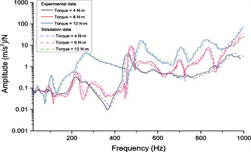
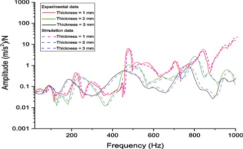
Fig. 11 represents FRFs for viscoelastic layer with different thicknesses. It can be found that the amplitude is reduced significantly with the increasing thickness of viscoelastic layer. The peak frequency is also changed to a large extent simultaneously. When the viscoelastic material thickness is adjusted, the properties of interface is changed, such as Coulomb friction and shear force of viscoelastic layer, even though in the situation of unchanged tightening force. Therefore, the whole structure stiffness change has been made via the changes of the thickness of the viscoelastic layer. It also illustrates that some peak frequencies can be avoided in vibration. Furthermore, the thickness of viscoelastic material should be controlled within a certain range, otherwise the eigen-frequency of the structure will decrease due to the larger viscoelasticity. Similarly, FEM results keep good accordance with the testing results.
Fig. 11Comparison of frequency response functions for the viscoelastic layer with different thicknesses
Through the laser testing on the different cross sections, the magnitudes of response amplitudes in tangential direction are respectively compared under various preloads and thicknesses of viscoelastic layers. From Fig. 12 and 13, it can be seen that the numerical results show good agreement with the experimental datum, which illustrates the accuracy of nonlinear modelling. Also, the response amplitudes for the middle plate are larger than those for the upper plate in shear excitation, and with the increasing of bolt preload, the difference of response amplitude for each torque becomes smaller gradually.
This is mainly due to that the excitation point is located on the cross section of the middle plate and when the preload reaches a certain degree, the stiffness of interface with viscoelastic layer increases little, which makes the change of tangential displacements of both smaller. Moreover, these two graphs indicate that when the preload is adjusted from loose to tight, the displacement response amplitude of the cross section is obviously reduced due to the increasing Coulomb friction and the sandwich viscoelastic material, and the time to reach the maximum displacement becomes longer.
The maximum displacement distribution diagram for viscoelastic layer with different thickness in one cycle is shown in Fig. 14. It can be seen that the maximum amplitude is changed with the increasing thickness of viscoelastic layer. It indicates that the elasticity of the material has a more significant effect on the response amplitude than viscous damping in shear vibration for the bolted joint structure and the tangential stiffness is reduced slightly even though the preload remains unchanged.
Fig. 12Displacement response amplitude of cross section of the upper plate for various bolt torque levels when the excitation amplitude Fexc= 15 N
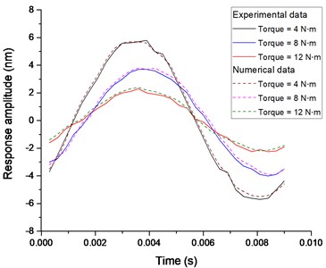
Fig. 13Displacement response amplitude of cross section of the middle plate for various bolt torque levels when the excitation amplitude Fexc= 15 N
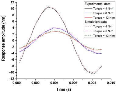
Fig. 14The maximum displacement distribution (nm) of cross section of the upper and middle plate when the excitation amplitude Fexc= 15 N
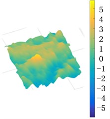
a) The thickness = 1 mm
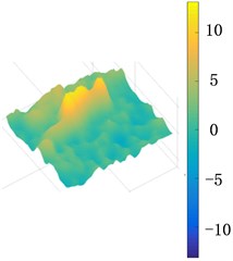
b) The thickness = 2 mm
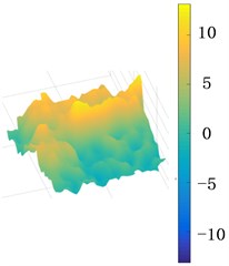
c) The thickness = 3 mm
5. Conclusions
In this work, the modeling and analysis of nonlinear dynamic response for the double shear lap joint structure with viscoelastic layer are studied. Based on phenomenological model, a four DOFs model is developed to predict the system’s dynamic response characteristics under the harmonic shear excitation. The influence of Coulomb friction and excitation levels on vibration are also addressed. Meanwhile, a FEM model with nonlinear stiffness with respect to contact algorithm is established, where the nonlinear behaviors under the various bolted preloads and viscoelastic layer thicknesses are presented. From the comparison between simulation and experiment results, it is worth noting that the viscoelastic layer help reduce the response of the composite structure to vibrations, especially significantly in the high frequency region, and the whole structure stiffness change can be achieved by adjusting the thickness of the viscoelastic layer. Furthermore, the simulation results are in good agreement with the experimental results.
References
-
Rao M. D. Recent application of viscoelastic damping for noise control in automobiles and commercial airplanes. Journal of Sound and Vibration, Vol. 262, Issue 3, 2003, p. 457-474.
-
Borges F. C. L., Roitman N., Magluta C., et al. A concept to reduce vibrations in steel catenary risers by the use of viscoelastic materials. Ocean Engineering, Vol. 77, 2014, p. 1-11.
-
Chen W., Liu S. Topology optimization of microstructures of viscoelastic damping materials for a prescribed shear modulus. Structural and Multidisciplinary Optimization, Vol. 50, Issue 2, 2014, p. 287-296.
-
Park S. W. Analytical modeling of viscoelastic dampers for structural and vibration control. International Journal of Solids and Structures, Vol. 38, Issue 44, 2001, p. 8065-8092.
-
Rouleau L., Deü J. F., Legay A., Sigrist J. F. Vibro-acoustic study of a viscoelastic sandwich ring immersed in water. Journal of Sound and Vibration, Vol. 331, Issue 3, 2012, p. 522-39.
-
Esteban J., Rogers C. A. Energy dissipation through joints: theory and experiments. Computers and Structures, Vol. 75, Issue 4, 2000, p. 347-59.
-
Sinou J. J., Jezequel L. Mode coupling instability in friction-induced vibrations and its dependency on system parameters including damping. European Journal of Mechanics-A/Solids, Vol. 26, Issue 1, 2007, p. 106-122.
-
Bograd S., Reuss P., Schmidt A., Gaul L., Mayer M. Modeling the dynamics of mechanical joints. Mechanical Systems and Signal Processing, Vol. 25, Issue 8, 2011, p. 2801-2826.
-
Kim J., Yoon J. C., Kang B. S. Finite element analysis and modelling of structure with bolted joints. Applied Mathematical Modelling, Vol. 31, Issue 5, 2007, p. 895-911.
-
Liu S. G., Ma Y. H., Zhang D. Y., Hong J. Studies on dynamic characteristics of the joint in the aero-engine rotor system. Mechanical Systems and Signal Processing, Vol. 29, 2012, p. 120-136.
-
Miller J. D., Quinn D. D. A two-sided interface model for dissipation in structural systems with frictional joints. Journal of Sound and Vibration, Vol. 321, Issue 12, 2009, p. 201-219.
-
Mohanty P., Rixen D. J. Operational modal analysis in the presence of harmonic excitation. Journal of Sound and Vibration, Vol. 270, Issue 12, 2004, p. 93-109.
-
Allemang R. J., Brown D. L. A complete review of the complex mode indicator function (CMIF) with applications. Proceedings of International Conference on Noise and Vibration Engineering (ISMA), Belgium, 2006, p. 3209-3246.
-
Stahle C. V., Staley J. A. Application of damping to spacecraft structures. Proceedings of the National SAMPE Symposium and Exhibition, 1984, p. 185-194.
-
Wang R., Crocombe A. D., et al. Energy dissipation in spacecraft structures incorporating bolted joints with viscoelastic layers. Proceedings of the iMeche, Part G: Journal of Aerospace Engineering, Vol. 222, Issue G2, 2007, p. 201-211.
-
Motosh N. Development of design charts for bolts preloaded up to the plastic range. Journal of Manufacture Science and Engineering – Transactions of the ASME, Vol. 98, 1976, p. 849-851.
Cited by
About this article

This work has been funded by Science and Technology Support Planning of Jiangsu province (Approval No. BE2014004-3), The Technology Grand Special Project (Approval No. 2013ZX04012032, No. 2012ZX04002032).
