Abstract
The effect of poor soil condition and unbalanced weight of the turbo machineries can lead to increased amplitudes of vibration which are further multiplied if subjected to seismic loading. In the current work, a computational model for the turbo machinery foundation was developed in SAP 2000 software to analyze the effect of Kathmandu earthquake (2015) in five different soil conditions i.e. very hard generic rock, generic rock, generic soil, NEHRP C class and NEHRP D class. The results reveal that turbo machinery foundation with barrettes can be used in seismic areas as barrettes safeguard the foundation by absorbing/reducing the seismic load due to high specific surface and side resistance. However for poor soil conditions like NEHRP D (clay soil), it was found that barrettes alone are not sufficient to limit the vibrations induced by either dynamic loading due to rotating motion of the machineries or seismic loading. Applications of geosynthetics along with barrettes considerably reduce the vibrations at top deck for poor soil conditions.
1. Introduction
Continuous improvements in power generation technologies lead to gigantic turbo machineries which generate considerably higher dynamic forces and stresses on the foundation. The machine foundations should be designed so as to transmit the dynamic forces of machines to the soil through the foundation thus negating the harmful effects due to vibration [1, 2]. During the design stage, a detailed vibration analysis for the turbo machine foundation needs to be carried out for investigating the dynamic behavior of foundation and its satisfactory performance. As turbo machineries are present in different geographies including highly seismic vulnerable areas across the world, the analysis must be carried out for different soil conditions so as to design the machine foundation that resists strong earthquake levels.
The behavior of foundation subjected to dynamic loads is highly dependent on the type of machine as well as operating frequency, soil state, depth of embedment and method of analysis [3]. Fattah et al. (2015) [4] carried out a parametric study of the machine foundation with pile using the ANSYS software to find out the geometry, amplitude and frequency of the dynamic load of the machine. They have reported that the final settlement of the foundation increases with increasing the amplitude of dynamic force, operating frequency and degree of saturation. Ming, et al. (2012) [5] studied a turbine foundation system with dynamic loadings from rotor movement and earthquakes. They have found that the displacement and internal forces of the rotary equipment foundation system are strongly influenced by effect of soil structure interaction. Tripathy and Desai (2016) [6] studied the effect of raft, pile with raft and barrettes with raft subjected to harmonic load on the turbo-generator foundation in medium dense and partially saturated sand. They have carried out both the experimental and numerical analysis using SAP 2000 and reported that the displacement at the top deck is lower for barrettes compared to raft and pile structures, which results in the least vibration at the top deck for barrette-supported turbo generator foundations. Barrettes can be used as an effective alternative to a large diameter bored and cast in place piles, due to their high specific surface area compared to circular piles [7]. Thasnanipan, et al. [8] have found that barrettes are satisfactory in layered soil static load up to 52,900 kN for the fifty-story building foundation in Bangkok.
Natural records for an earthquake are very much limited mostly due to the absence of nearby seismic stations in the earthquake site or because of low seismicity variation [9]. An actual seismic record is a non-stationary and nonlinear time series and hence the accuracy of the generated signal to record the natural properties and the characteristics are very much important. The main concern for the seismic analysis is to generate a set of motions which should be consistent with the soil classification for seismic design in the USA (NEHRP-2003). Boore et al. [10] reported the amplification values as frequency dependent functions for assessment of the NEHRP (1997) soil profiles viz. generic very hard rock (Vs-2900 m/s), generic rock (Vs-620 m/s), generic soil (Vs-310 m/s), NEHRP C class (Vs-520 m/s), and NEHRP D class (Vs-255 m/sec).
In Malaysia, due to a lack of recorded representative strong motion data, synthetic ground motions were generated in the frequency domain by carrying out a spectral matching analysis and application of random vibration theory [11]. Vrochidou [9] had compared the generated time history in SeismoArtif software with the values obtained from the Hilbert-Huang transform method.
In the current work, a turbo machinery foundation model with barrettes is developed in SAP 2000 software. Earthquake loading is applied to the model in north-east and south-west direction by considering Nepal Kathmandu time history in five different soil conditions i.e. NEHRP C, NEHRP D, Generic soil, Generic rock and Generic very hard rock. Vibration at top deck, bending moment at bottom raft, base shear and shear force parameters are studied for the model during application of dynamic loading. For the poorest soil NEHRP D, further parametric analysis is carried out with and without consideration of geosynthetics.
2. Numerical modeling
2.1. Modeling of turbo machinery foundation
The turbo machinery foundation consists of top deck, raft, columns, beams and barrettes. Shell elements are used for top deck and bottom raft, whereas frame elements have been used for beams and columns. The top deck and bottom raft of the foundation are modeled with four nodded shell elements. The top deck and bottom raft are divided into very fine meshes for carrying out vibration analysis. Similarly, barrettes are modeled using a series of nonlinear frame elements. Barrette has been divided into various nodes and the non-linear soil springs and dashpot have been attached to each node. Soil springs are also attached to each mesh of the bottom raft. Below steps are followed for designing the computational model.
Grid pattern with the dimensions of Length 38 m width 10 m and height of 36 m was selected. Then the bottom raft has been selected at a height of 22 m from bottom and the raft area has been drawn. Finally, the raft area was converted to shell elements of thickness 3 m.
At the top of the bottom raft, 14 nos of column with height 11.6 m been selected with the help of frame elements.
At the top of the column, beam elements has been placed. The joint represents common node for both beam and column.
At the height of 33.6 m, top deck area was drawn with dimensions 8 m×35 m and the area was converted into shell elements of thickness 1.5 m.
, , , , are the compressor and the turbine loads which were modeled as the rigid links. The rigid links were modeled in such a way that they are acting at the Centre of Gravity (CG) of the compressors and turbines. Sine loads were applied at the center of rigid link which represents the harmonic motion due to rotation of turbo machinery.
Columns were extended to the bottom of the raft of 19 m which forms the barrettes and were designed with the help of frame elements.
Entire structure was meshed into fine mess (0.5 m×0.5 m×0.5 m) by applying the auto meshing option in SAP 2000.
Geosynthetic has been modeled as a shell element. It has connected to the periphery of the barrettes.
Soil has been modeled as links which has 6 degrees of freedom (DOF) and it has been assigned to each mesh of the raft and each node of barrettes.
The foundation has been modeled using two parameters: the modulus of elasticity and Poisson’s ratio. The foundation material is considered to be reinforced concrete of grade M30. Value of Young’s Modulus (), Poisson’s ratio () and density of concrete are taken as 22.36 GPa, 0.15 and 25 kN/m3 respectively. Fig. 1. shows the detailed model of a turbo machine foundation in SAP: 2000. The machine component and foundation data considered for the model are mentioned in Table 1.
Table 1Machine component and foundation data
Machine component and foundation data | |
Machine running speed during normal operation | 3995 rpm (65 Hz) |
Bottom raft dimension | 38 m () × 8 m () × 3.0 m () |
Top deck dimension | 35 m () × 8 m () × 1.5 m () |
Compressor weight ) | 1311 kN |
Compressor weight () | 1445 kN |
Compressor weight () | 1445 kN |
Compressor weight () | 2045 kN |
Turbine weight () | 1361 KN |
Condenser weight | 995 kN |
Fig. 1Detailed model of turbo machine foundation in SAP: 2000
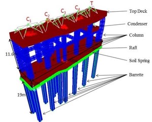
a) Turbo machinery foundation raft with Barrettes
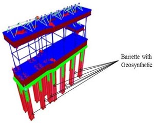
b) Turbo machinery foundation raft with Barrettes with geosynthetics
2.2. Modeling of machine components
Machine components are modeled as rigid links placed on the top deck of the foundation. Rotating speed of the machine is considered as 3995 rpm in the study.
2.3. Modeling of soil/geosynthetics
The Lysmer and Richart’s [12] method is used to calculate stiffness and damping values soil spring. Soil springs has been modeled using the linear link elements. The geosynthetic material considered in the study has Young modulus of 2000 MPa and Poisson’s ratio of 0.15. The geosynthetic material has been modeled as shell element.
2.4. Forced vibration analysis
Vibration occurs in the foundation due to harmonic loads from machine. The unbalanced forces are due to weight of the motor and the rotational motion. Sine functions are added at the top deck to model the harmonic dynamic loads of the machine which are transmitted through rigid links. Similarly, earthquake time history is applied at the bottom of the raft for carrying out seismic excitation and vibration analysis.
2.5. Generation of synthetic time history
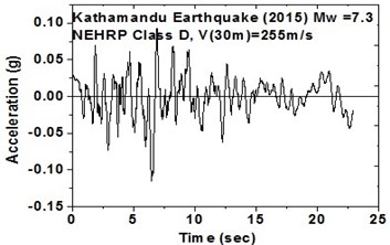
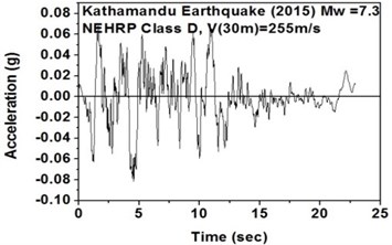
The SeismoArtif software has been used for generating a synthetic time history at different soil conditions with the application of Kathmandu earthquake. The software uses the Hallodorson and Papageorgiou [13] algorithm for generating a synthetic accelerogram. Real time history of the Kathmandu earthquake is taken from the PEER database and plotted in Fig. 2. Same has been used in SeismoArtif software for generating the time history for different soil conditions. The peak ground acceleration values for the generated earthquakes obtained from SeismoArtif are summarized in Table 2. Fig. 3 shows input time histories generated for different soil conditions in SeismoArtif. These time histories are applied to the computational model in SAP2000 at the bottom of the raft for carrying out the seismic analysis of the structure.
Table 2Earthquake motions obtained from SeismoArtif
Sl. No. | Generated Earthquake with different soil conditions | Year | Magnitude | Dist. (km) | Peak ground acceleration PGA (g) | Peak ground velocity PGV (cm/s) | Peak ground displacement PGD (cm) |
1 | NEHRP D (NE) | 2015 | 7.3 | 10 | 0.084 | 38.938 | 56.623 |
2 | NEHRP D (SW) | 2015 | 7.3 | 10 | 0.115 | 37.885 | 67.872 |
3 | NEHRP C(NE) | 2015 | 7.3 | 10 | 0.107 | 15.173 | 20.67 |
4 | NEHRP C (SW) | 2015 | 7.3 | 10 | 0.079 | 14.511 | 8.058 |
5 | Generic soil (NE) | 2015 | 7.3 | 10 | 0.096 | 34.245 | 38.898 |
6 | Generic soil (SW) | 2015 | 7.3 | 10 | 0.098 | 30.22 | 48.601 |
7 | Generic rock (NE) | 2015 | 7.3 | 10 | 0.108 | 53.004 | 95.518 |
8 | Generic rock (SW) | 2015 | 7.3 | 10 | 0.072 | 41.943 | 74.803 |
9 | Generic hard rock (NE) | 2015 | 7.3 | 10 | 0.104 | 198.5 | 1185.97 |
10 | Generic hard rock (SW) | 2015 | 7.3 | 10 | 0.096 | 81.302 | 207.114 |
Fig. 2Real time history for Kathmandu earthquake
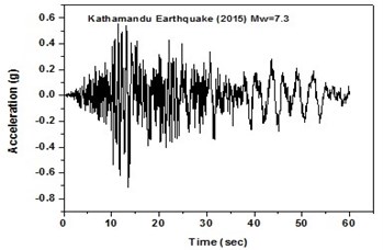
a) Time history in north-east direction
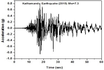
b) Time history in south-west direction
3. Results and discussion
3.1. Vibration at top deck of turbo machinery foundation
Vibration is defined as the differential displacement which is compared between two displacements occurring in a structure. There is a relative displacement on the machinery foundation due to a static load such as heavy machineries and dynamic relative displacements due to sine loading and earthquake loading. Due to dynamic loads, crack may occur at the top deck and column which sometimes may lead to bottom raft settlement.
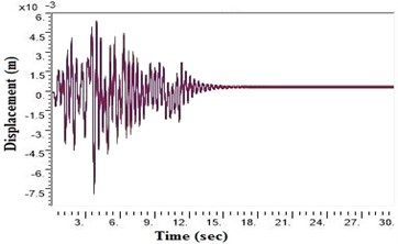
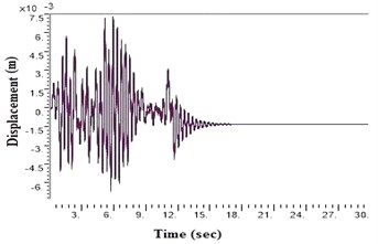
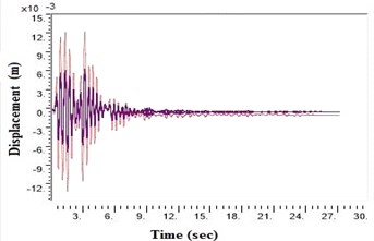
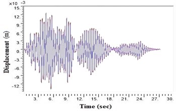
Fig. 3Time histories for Kathmandu earthquake with soil classification for seismic design in USA (NEHRP-2003)
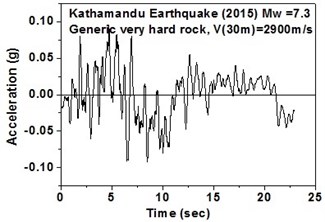
a) Generic very hard rock in north-east direction
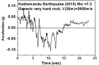
b) Generic very hard rock in south-west direction
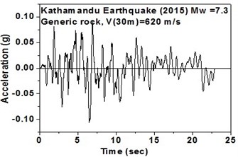
c) Generic rock in north-east direction
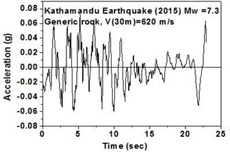
d) Generic rock in south-west direction
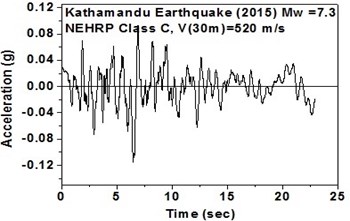
e) NEHRP Class C soil in north-east direction
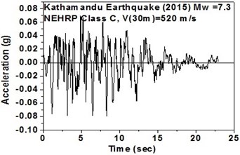
f) NEHRP Class C soil in south-west direction
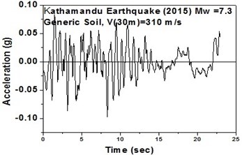
g) Generic soil in north-east direction
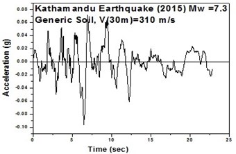
h) Generic soil in south-west direction
i) NEHRP Class D soil in north-east direction
j) NEHRP Class D soil in south-west direction
Fig. 4Displacement values at top deck near sine loading for NEHRP D Class soil before applying Kathmandu earthquake in barrettes
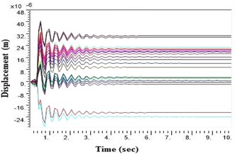
a) Displacement without geosynthetics in barrettes
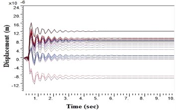
b) Displacement with geosynthetics in barrettes
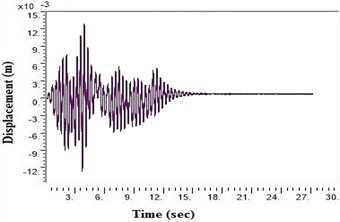
Fig. 5Displacement values at top deck near sine loading for different soil types after applying Kathmandu earthquake
a) Generic very hard rock
b) Generic rock
c) NEHRP Class C
d) Generic soil
e) NEHRP Class D without geosynthetics
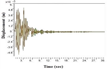
f) NEHRP Class D with geosynthetics
During a strong motion earthquake, the turbo machinery foundation often vibrates out of phase due to their different dynamic characteristics. The out-of-phase motion of the machinery foundation will lead to relative displacement if the top deck has insufficient capacity for handling the dynamic motions of the machinery parts. Accelerations which are applied to the column, bottom raft and barrettes are influenced by the magnitude and duration of the earthquake, type of soil and distance from the epicenter. Fig. 4. shows the vibrations of the machineries at the top deck in NEHRP D Class soil condition which is unsuitable for a turbo machinery foundation. After providing the geosynthetics in barrettes, the vibration has been reduced to 20 microns which is within permissible limit. Fig. 5. shows the vibrations at top deck in different soil conditions after applying the Kathmandu earthquake time history generated for different soils.
3.2. Bending moment at bottom raft
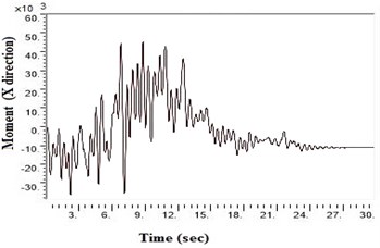
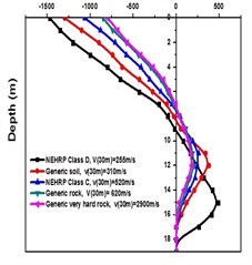
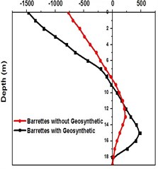
SAP2000 is used to determine shears and moments in the turbo machinery foundation. If the unbalance forces are generated on the foundation due to any reasons, it will have components in the horizontal () directions, which will in-turn generate horizontal moments. Hence it becomes necessary to study the moments of turbo machinery foundation. Fig. 6. shows the bending moment at the base of the raft for different soil conditions under Kathmandu earthquake loading. The base moment at direction is found to be higher for NEHRP D soil conditions compared to the other soils, which is reduced by the application of geosynthetics. The moment profiles along the barrette length for different soils with Kathmandu earthquake loading are shown in Fig. 7. The maximum bending moment has been observed at the top of the barrette probably due to the rigidity of the raft-barrette connection. Bending moment developed at barrette top is positive, which reduces to negative along the barrette length and then becomes zero towards at the barrette end. Negative to positive crossover point is found at shallow barrette depths for all types of soil conditions.
Fig. 6Moment values at bottom raft in X direction after applying Kathmandu earthquake
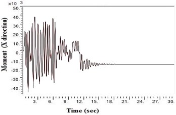
a) Generic very hard rock
b) Generic rock
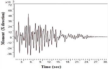
c) NEHRP Class C
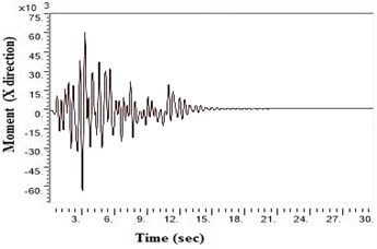
d) Generic soil
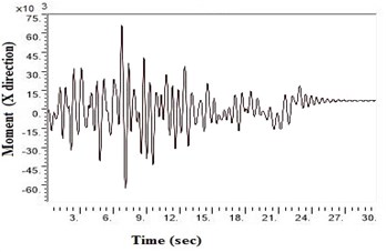
e) NEHRP Class D without geosynthetics
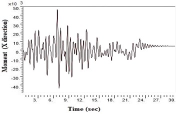
f) NEHRP Class D with geosynthetics
Fig. 7Bending moment along Barrette for Kathmandu time history loading
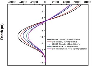
a) Bending moment for different types of soil with barrette
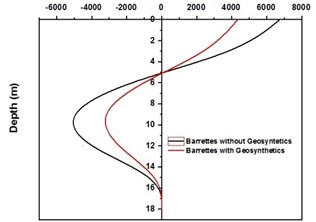
b) Bending moment for NEHRP D soil with Barrettes (with and without geosynthetics)
3.3. Base shear and shear force
Base shear is the maximum expected lateral force at the base of a structure due to seismic ground motion. It depends upon the site soil conditions, seismic ground motion and vibration period of the structure when subjected to dynamic loads. From Fig. 8(a) and (b), it is evident that the turbo machinery foundations with barrette in NEHRP D soil condition have high base shear, and by providing geosynthetics it can be reduced. Fig. 9 shows the negative shear force at the top then increases to a positive value at the bottom then reduces to zero.
Fig. 8Base shear for turbo generator foundation for Kathmandu time history loading
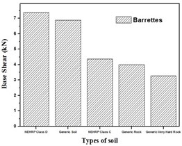
a) Base shear for different types of soil with barrette
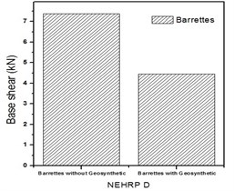
b) Base shear for NEHRP D soil with Barrettes (with and without geosynthetics)
Fig. 9Shear force along barrette for Kathmandu time history loading
a) Base shear for different types of soil with barrette
b) Base shear for NEHRP D soil with Barrettes (with and without geo synthetics)
4. Conclusions
A turbo machinery foundation model with barrette has been analyzed to determine the effects of the soil structure interaction under seismic loading. From the analysis, it is concluded that barrettes with raft are suitable for high seismic areas in all soil conditions because they transfer seismic reaction through columns to barrettes thus increasing the stability and durability of the turbo machinery foundation. It is also found that for poorest soil like NEHRP D condition, the displacement, bending moment and base shear of foundation increase as compared to other soils when subjected to strong motion earthquake. By providing geosynthetics in the barrettes, the displacement at top deck can be minimized for poor soils. Hence for poor soil conditions, barrettes with geosynthetics are recommended.
References
-
Barkan D. D. Dynamics of Bases and Foundations. McGraw-Hill Book Company, New York, U.S.A, 1962.
-
Major A. Dynamics in Civil Engineering-Analysis and Design, Vols. I-IV, Akadémiai Kiadó, Budapest, Hungary, 1980.
-
Fattah M. Y., Al-Mosawi M. J., Al-Ameri A. F. I. Vibration response of saturated sand foundation system. Earthquakes and Structures, Vol. 11, Issue 1, 2016, p. 83-107, https://doi.org/10.12989/eas.2016.11.1.083.
-
Fattah M. Y., Al-Nakdy I. A. M., Hamood M. J. Finite-element analysis of piled machine foundation, structures and buildings. Proceedings of the Institution of Civil Engineers, Vol. 168, Issue 6, 2015, p. 421-432., https://doi.org/10.1680/stbu.14.00053.
-
Ming F., Tao W., Hui L. Dynamic behaviour of turbine foundation considering full interaction among facility, structure and soil. Proceedings of the 15th World Conference on Earthquake Engineering, Lisbon, Portugal, 2008.
-
Tripathy S., Desai A. Investigation of dynamic behaviour for turbo generator frame foundation through experimental and computational approach. International Journal of Geotechnical Engineering, 2016, https://doi.org/10.1080/19386362.2016.1239037.
-
Ramaswamy S. D., Pertusier E. M. Construction of Barrettes for high-rise foundations. Journal of Construction Engineering Management, Vol. 112, Issue 4, 1986, p. 455-462.
-
Thasnanipan N., Aye Z., Teparaksa W. Barrette of over 50,000 kN ultimate capacity constructed in the multi-layered soil of Bangkok. Deep Foundations, 2002, p. 1073-1087.
-
Vrochidou E., Alvanitopoulos P. F., Andreadis I., Elenas A., Mallousi K. Synthesis of artificial spectrum-compatible seismic accelerograms. Measurement Science and Technology, Vol. 25, Issue 8, 2014, p. 1-31.
-
Boore D. M., Joyner W. B. Site amplifications for generic rock sites. Bulletin of the Seismological Society of America, Vol. 87, Issue 2, 1997, p. 327-341.
-
Adnan A., Marto H. A., Irsyam M. Development of synthetic time histories at bedrock for Kuala Lumpur. Proceedings of the 6th Asia-Pacific Structural Engineering and Construction Conference, Kuala Lumpur, Malaysia, 2006.
-
Lysmer J., Richart F. E. Dynamic response of footing to vertical loading. Journal Soil Mechanics Foundation Division, Vol. 92, Issue 1, 1966, p. 65-91.
-
Halldorsson B., Papageorgiou A. S. Calibration of the specific barrier model to earthquake of different tectonic regions. Bulletin of the Seismological Society of America, Vol. 95, Issue 4, 2005, p. 1276-1300.
About this article

