Abstract
In this paper, the finite element software ANSYS Workbench 14.0 is used to analyze the moment-curvature and ovalization-curvature relationships of 6061-T6 aluminum alloy tubes with a local sharp cut under curvature-controlled symmetrical cyclic bending. The cut depths of 0.4, 0.8, 1.2, 1.6 and 2.0 mm were considered. The experimental moment-curvature relationship exhibited an almost steady loop from the beginning of the first cycle; the cut depth had almost no influence on the curves. Moreover, the ovalization-curvature curve increased in an increasing, unsymmetrical and ratcheting manner with the number of bending cycles. Large cut depths resulted in larger ovalization of the tube cross-section. The ANSYS analysis was compared with the experimental finding. The simulated results exhibited close correspondence to those obtained from the experiments.
1. Introduction
It is well known that the bending of circular tubes results in the ovalization (change in the outer diameter divided by the original outer diameter) of the tube cross-section. This ovalization increases slowly during reverse bending and continuous cyclic bending and, in turn, results in the deterioration of the circular tube, which buckles when the ovalization reaches some critical value. The circular tube is severely damaged during buckling and cannot bear the load, which ultimately results in obstruction and leakage of the material being transported. As such, a complete understanding of the response of the circular tube to cyclic bending is essential for industrial applications.
As part of the earliest research regarding this issue, Shaw and Kyriakides [1] designed and constructed a tube cyclic bending machine and conducted a series of experimental and theoretical investigations. Kyriakides and Shaw [2] later investigated the inelastic behavior of tubes subjected to cyclic bending and extended the analysis of tubes to stability conditions under cyclic bending. Corona and Kyriakides [3] investigated the stability of tubes subjected to combined bending and external pressure; they also later[4] studied the degradation and buckling of tubes under cyclic bending and external pressure. Corona and Vaze [5] studied the response, buckling, and collapse of long, thin-walled seamless steel square tubes under bending, and later they [6] experimentally investigated the elastic-plastic degradation and collapse of steel tubes with square cross-sections under cyclic bending. Corona and Kyriakides [7] also studied the asymmetric collapse modes of pipes under combined bending and pressure. Corona et al. [8] conducted a set of bending experiments on aluminum alloy tubes to investigate the yield anisotropy effects on buckling. Later, Kyriakides et al. [9] studied the plastic bending of steel tubes with a diameter-to-thickness ratio ( ratio) of 18.8, exhibiting Lüders bands through the experiment. Limam et al. [10] studied the inelastic bending and collapse of tubes in the presence of bending and internal pressure. Later, Limam et al. [11] later investigated the collapse of dented tubes under combined bending and internal pressure. Bechle and Kyriakides studied the localization in NiTi tubes under bending [12].
Additionally, other scholars have published a number of related studies. Elchalakani et al. [13] experimentally conducted tests on different ratios of grade C350 steel tubes under pure bending and proposed two theoretical simulation models. Jiao and Zhao [14] tested the bending behavior of very high strength circular steel tubes and proposed a plastic slenderness limit. Houliara and Karamanos [15] investigated the buckling and post-buckling of long-pressurized, elastic, thin-walled tubes under in-phase bending. Elchalakani et al. [16] conducted the variable amplitude, cyclic, pure bending tests to determine fully ductile section slenderness limits for cold-formed CHS. Mathon and Liman [17] experimentally studied the collapse of thin, cylindrical shells that were submitted to internal pressure and pure bending. Elchalakani and Zhao [18] investigated concrete-filled, cold-formed circular steel tubes that were subjected to variable amplitude, cyclic, pure bending. Fatemi et al. [19] discussed the parameters that affect the buckling and post-buckling behavior of high strength pipelines under bending. Yazdani and Nayebi [20] discussed the ratcheting and fatigue damage of thin-walled tubes under cyclic bending and steady internal pressure. Jiang et al. [21] experimentally investigated and designed the thin-walled concrete-filled steel tubes under Bending. Shariati et al. [22] experimental studied the SS316 cantilevered cylindrical shells subjected to cyclic bending.
In 1998, Pan et al. [23] designed and set up a new measurement apparatus. It was used with the cyclic bending machine to study various kinds of tubes under different cyclic bending conditions. For instance, Pan and Her [24] investigated the response and stability of 304 stainless steel tubes that were subjected to cyclic bending with different curvature-rates, Lee et al. [25] studied the influence of the ratio on the response and stability of circular tubes that were subjected to symmetrical cyclic bending, Lee et al. [26] experimentally explored the effect of the ratio and curvature-rate on the response and stability of circular tubes subjected to cyclic bending, and Chang and Pan [27] discussed the buckling life estimation of circular tubes subjected to cyclic bending.
In practical industrial applications, tubes are in hostile environments, so the material in the environment may corrode the tube surface and produce notches. Additionally, when using a tube, it must have a notch design. The mechanical behavior and buckling failure of a notched tube differs from that of a tube with a smooth surface. In 2010, Lee et al. [28] studied the variations in ovalization that occur in sharp-notched circular tubes subjected to cyclic bending. Lee [29] later investigated the mechanical behavior and buckling failure of sharp-notched circular tubes under cyclic bending, and Lee et al. [30] experimentally discussed the viscoplastic response and collapse of sharp-notched circular tubes subjected to cyclic bending.
Fig. 1Pictures of a) a tube with a circumferential sharp notch, b) a tube with a local sharp notch and c) a tube with a local sharp cut
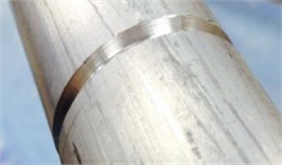
a)
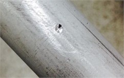
b)

c)
However, all investigations of the sharp notch were the circumferential sharp notch as shown in Fig. 1(a). If the sharp notch is a local sharp notch (Fig. 1(b)), the response of a local sharp notch tube under cyclic bending should be different from that of a circumferential sharp notch tube under cyclic bending. Therefore, Lee et al. [31] investigated the response of local sharp-notched circular tubes with different notch depths subjected to cyclic bending.
It is known that the tubes may be damaged by a sharp object during the delivery, installation or use. Once a local sharp cut is on a tube (Fig. 1(c)), the response of the tube under cyclic bending should be different from that of a smooth or other kind of notched tube under cyclic bending. Therefore, the response of tubes with a local sharp cut under cyclic bending is investigated in this paper.
2. Experiment
The experiments were performed in a specially built testing apparatus, which is shown schematically in Fig. 2(a). This apparatus was designed for conducting the bending, reverse, and cyclic bending test and detailed descriptions thereof are provided elsewhere [24-28]. Pan et al. [23] designed a light-weight instrument, shown schematically in Fig. 2(b), for measuring the curvature and ovalization of the tube cross section. The two side inclinometers measure the angle changes during cyclic bending and the curvature of the tube can be determined through a simple mathematical calculation (extended version of the instrument and the calculation are described in Pan et al. [23]).
Fig. 2a) A schematic drawing of the bending device, b) a schematic drawing of the curvature-ovalization measurement apparatus
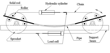
a)
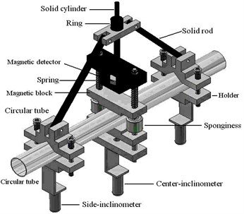
b)
Circular tubes made of 6061-T6 aluminum alloy were used in this study. Table 1 shows the alloy’s chemical composition. The ultimate stress was 258 MPa, the 0.2 % strain offsetting the yield stress () as 166 MPa, and the percent elongation was 23 %. The raw, unnotched 6061-T6 aluminum alloy tubes had an outside diameter of 35.0 mm, a wall thickness of 3.0 mm and a tube length of 50 mm. The raw tubes were machined on the outside surface to obtain the desired shape and depth of the sharp cut. Fig. 3(a) shows a schematic drawing of the tube with a sharp cut where the cut depth is denoted as . In this study, five different cut depths were considered including 0.4, 0.8, 1.2, 1.6 and 2.0 mm, respectively. The cut root radius for all tested tubes was controlled to be less than 1/100 mm and all tested tubes were carefully examined before the test. Fig. 3(b) shows a picture of the tested 6061-T6 aluminum alloy tubes with different cut depths.
Table 1Chemical composition of 6061-T6 aluminum alloy (weight %)
Chemical composition | Al | Mg | Si | Cu | Ti | Fe |
Proportion (%) | 97.40 | 0.916 | 0.733 | 0.293 | 0.268 | 0.256 |
Chemical composition | Mn | Zn | Cr | Ni | Pb | Sn |
Proportion (%) | 0.132 | 0.0983 | 0.0682 | 0.0056 | 0.005 | <0.001 |
The bending experiments were performed under curvature-controlled conditions and curvatures were applied at loading curvature rates of 0.03 m-1/s. The two load cells installed in the testing apparatus (Fig. 2(a)) were used to measure the bending moment. Moreover, the light-weight instrument (Fig. 2(b)) was used to measure the curvature and ovalization of the tube cross-section.
Fig. 3a) A Schematic drawing of a tube with a sharp-cut depth of a, b) a picture of the tested 6061-T6 aluminum alloy tubes with different cut depths
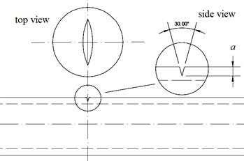
a)
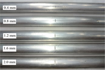
b)
3. Finite element analysis
A uniaxial cyclic stress-strain curve was constructed multilinearly in ANSYS shown in Fig. 4(b) according to the tested uniaxial cyclic stress-strain curve for 6061-T6 aluminum alloy shown in Fig. 4(a). Additionally, the kinematic hardening rule was used for cyclic loading.
Fig. 4(a) Tested and (b) ANSYS constructed data of the uniaxial cyclic stress-strain curves for 6061-T6 aluminum alloy
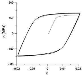
a)

b)
Owing to the three-dimensional geometry and elastoplastic deformation of the tube, the SOLID 185 element was used for relative analysis. This element is a tetrahedral element built in ANSYS, which is suitable for analyzing plastic and large deformations. In particular, this element is adequate for analyzing shell components subjected to bending. Moreover, owing to the right-left symmetry, only half of the tube model was constructed. Fig. 5 shows the mesh constructed by ANSYS.
Fig. 5Mesh constructed by ANSYS for half tube
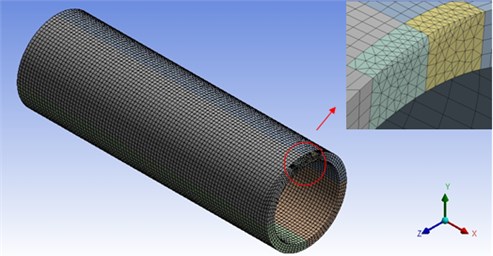
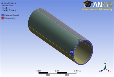
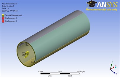
Fig. 6(a) shows the restrictions on the symmetrical plane (central cross section), constructed by ANSYS, for a tube subjected to cyclic bending. Since the tubes were bent in the -direction only, the frictionless roller support was fixed to the symmetrical plane and the displacement in the -direction of this plane was set to zero. Fig. 6(b) shows the loading condition constructed by ANSYS on the basis of the tube bending device. As the figure shows, the remote displacement in the -direction was unrestricted, i.e., the rotation was free to move in the -direction. In addition, the bending moment was applied only in the -direction and hence, the rotations in the - and -directions were set to zero.
Fig. 6a) Restrictions on the symmetrical plane constructed by ANSYS, b) loading condition constructed by ANSYS
a)
b)
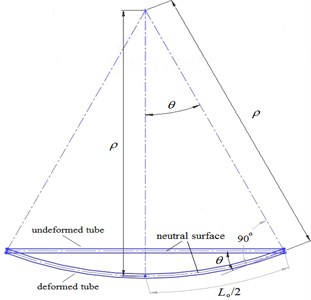
The rotation angle in the -direction (Fig. 7) was used as the input data for the tube subjected to curvature-controlled cyclic bending and is related to the curvature through:
where is the radius of curvature and is the original tube length.
Fig. 7Relationship between rotating angle θ and curvature κ for a tube under pure bending
4. Comparison of the experimental and ANSYS analysis results
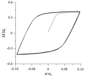
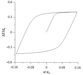
Fig. 8(a) shows a typical set of experimentally determined cyclic moment ()-curvature () curves for local sharp-cut 6061-T6 aluminum alloy tubes, with cut depth of 0.4 mm, subjected to cyclic bending. The moment and curvature were normalized by and , respectively (Corona and Kyriakides [3, 4]). The tubes were cycled between ±0.16. However, the - response was seen to be characterized by a nearly closed and steady hysteresis loop from the first cycle. Since the sharp cut is small and local, the cut depth has almost no influence on the - curve. Therefore, the - curves for different values of are not shown in this paper. Fig. 8(b) shows the - curve, as simulated by ANSYS. Since ANSYS cannot simulate the cyclic hardening, the cyclic - curve consists of only a single loop.
Fig. 8a) Experimental and b) ANSYS simulated moment (M/Mo) – curvature (κ/κo) curves for local sharp-cut 6061-T6 aluminum alloy tubes under cyclic bending with a= 0.4 mm
a)
b)
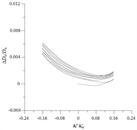
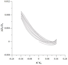
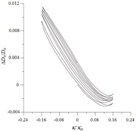
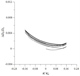
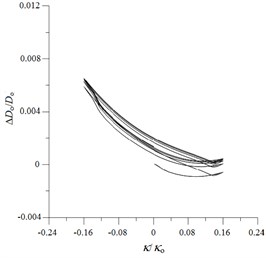
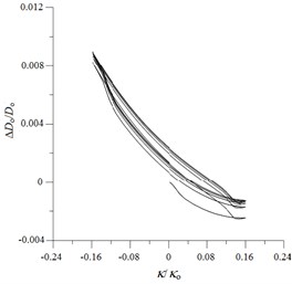
Fig. 9Experimental ovalization (ΔDo/Do) – curvature (κ/κo) curves for local sharp-cut 6061-T6 aluminum alloy tubes under cyclic bending
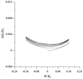
a) 0.4 mm
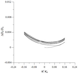
b) 0.8 mm
c) 1.2 mm
d) 1.6 mm
e) 2.0 mm
Figs. 9(a)-(e) show the experimentally determined ovalization ()-curvature () curves for local sharp-cut 6061-T6 aluminum alloy tubes subjected to cyclic bending; cut depths of 0.4, 0.8, 1.2, 1.6 and 2.0 mm were considered. The ovalization is defined as , where is the outside diameter and is the change in the outside diameter. It can be seen that the ovalization increases in a ratcheting and unsymmetrical manner with the number of bending cycles. A higher value of for the cut tube causes greater ovalization in the tube’s cross-section. In addition, higher values of for sharp-notched SUS304 stainless steel tubes led to more severe unsymmetrical trends in the - curve. This phenomenon of - curves is similar to that for local sharp-notched SUS304 stainless steel tubes subjected to cyclic bending [31]. But the unsymmetrical trend of - curves for local sharp-cut 6061-T6 aluminum alloy tubes is more significant than that for local sharp-notched SUS304 SUS304 stainless steel tubes. Figs. 10(a)-(e) depict the corresponding simulated - curves by ANSYS. The ANSYS simulated results exhibit close correspondence to those obtained from the experiments.
Fig. 10ANSYS simulated ovalization (ΔDo/Do) – curvature (κ/κo) curves for local sharp-cut 6061-T6 aluminum alloy tubes under cyclic bending
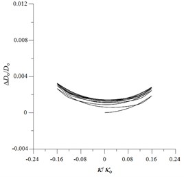
a) 0.4 mm
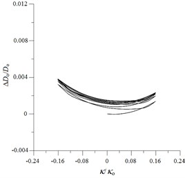
b) 0.8 mm
c) 1.2 mm
d) 1.6 mm
e) 2.0 mm
5. Conclusions
The response of local sharp-cut 6061-T6 aluminum alloy tubes with different cut depths subjected to cyclic bending were investigated in this study. On the basis of the experimental and theoretical results, the following conclusions can be drawn:
1) The - curves of local sharp-cut 6061-T6 aluminum alloy tubes with any cut depth exhibit a steady loop from the first cycle under curvature-controlled cyclic bending. In addition, the stable - loops have very similar shape and size irrespective of the cut depth.
2) The - curves show that the ovalization of the tube cross section increases in a ratcheting manner with increasing number of cycles. Higher leads to more unsymmetrical trends and larger ovalization of the tube cross-section compared with those obtained at lower values of .
3) Using adequate stress-strain relationships, mesh, boundary conditions, and loading conditions, the finite element software ANSYS can simulate the behavior of local sharp-cut circular tubes subjected to cyclic bending; this behavior includes the moment-curvature and ovalization-curvature relationships. The simulated results exhibited close correspondence to those obtained from experiments.
References
-
Shaw P. K., Kyriakides S. Inelastic analysis of thin-walled tubes under cyclic bending. International Journal of Solids and Structures, Vol. 21, Issue 11, 1985, p. 1073-1110.
-
Kyriakides S., Shaw P. K. Inelastic buckling of tubes under cyclic loads. Journal of Pressure Vessel and Technology, Vol. 109, Issue 2, 1987, p. 169-178.
-
Corona E., Kyriakides S. On the collapse of inelastic tubes under combined bending and pressure. International Journal of Solids and Structures, Vol. 24, Issue 5, 1988, p. 505-535.
-
Corona E., Kyriakides S. An experimental investigation of the degradation and buckling of circular tubes under cyclic bending and external pressure. Thin-Walled Structures, Vol. 12, Issue 3, 1991, p. 229-263.
-
Corona E., Vaze S. Buckling of elastic-plastic square tubes under bending. International Journal of Mechanical Sciences, Vol. 38, Issue 7, 1996, p. 753-775.
-
Vaze S., Corona E. Degradation and collapse of square tubes under cyclic bending. Thin-Walled Structures, Vol. 31, Issue 4, 1998, p. 325-341.
-
Corona E., Kyriakides S. Asymmetric collapse modes of pipes under combined bending and external pressure. Journal of Engineering Mechanics, Vol. 126, Issue 12, 2000, p. 1232-1239.
-
Corona E., Lee L. H., Kyriakides S. Yield anisotropic effects on buckling of circular tubes under bending. International Journal of Solids and Structures, Vol. 43, Issues 22-23, 2006, p. 7099-7118.
-
Kyriakides S., Ok A., Corona E. Localization and propagation of curvature under pure bending in steel tubes with Lüders bands. International Journal of Solids and Structures, Vol. 45, Issue 10, 2008, p. 3074-3087.
-
Limam A., Lee L. H., Corana E., Kyriakides S. Inelastic wrinkling and collapse of tubes under combined bending and internal pressure. International Journal of Mechanical Sciences, Vol. 52, Issue 5, 2010, p. 637-647.
-
Limam A., Lee L. H., Kyriakides S. On the collapse of dented tubes under combined bending and internal pressure. International Journal of Solids and Structures, Vol. 55, Issue 1, 2012, p. 1-12.
-
Bechle N. J., Kyriakides S. Localization in NiTi tubes under bending. International Journal of Solids and Structures, Vol. 51, Issue 5, 2014, p. 967-980.
-
Elchalakani M., Zhao X. L., Grzebieta R. H. Plastic mechanism analysis of circular tubes under pure bending. International Journal of Mechanical Sciences, Vol. 44, Issue 6, 2002, p. 1117-1143.
-
Jiao H., Zhao X. L. Section slenderness limits of very high strength circular steel tubes in bending. Thin-Walled Structures, Vol. 42, Issue 9, 2004, p. 1257-1271.
-
Houliara S., Karamanos S. A. Buckling and post-buckling of long pressurized elastic thin-walled tubes under in-plane bending. International Journal of Nonlinear Mechanics, Vol. 41, Issue 4, 2006, p. 491-511.
-
Elchalakani M., Zhao X. L., Grzebieta R. H. Variable amplitude cyclic pure bending tests to determine fully ductile section slenderness limits for cold-formed CHS. Engineering Structures, Vol. 28, Issue 9, 2006, p. 1223-1235.
-
Mathon C., Liman A. Experimental collapse of thin cylindrical shells submitted to internal pressure and pure bending. Thin-Walled Structures, Vol. 44, Issue 1, 2006, p. 39-50.
-
Elchalakani M., Zhao X. L. Concrete-filled cold-formed circular steel tubes subjected to variable amplitude cyclic pure bending. Engineering Structures, Vol. 30, Issue 2, 2008, p. 287-299.
-
Fatemi A., Kenny S., Sen M., Zhou J., Tahern F., Paulin M. Parameters affecting buckling and post-buckling behavior of high strength pipelines. Proceeding of the 28th International Conference on Ocean, Offshore Mechanics and Arctic Engineering, Hawaii, U.S.A, 2009.
-
Yazdani H., Nayebi A. Continuum damage mechanics analysis of thin-walled tube under cyclic bending and internal constant pressure. International Journal of Applied Mechanics, Vol. 5, Issue 4, 2013, p. 1350038.
-
Jiang A. O., Chen J., Jin W. L. Experimental investigation and design of thin-walled concrete-filled steel tubes subjected to bending. Thin-Walled Structures, Vol. 63, 2013, p. 44-50.
-
Shariati M., Kolasangiani K., Norouzi G., Shahnavaz A. Experimental study of SS316 cantilevered cylindrical shells under cyclic bending load. Thin-Walled Structures, Vol. 82, 2014, p. 124-131.
-
Pan W. F., Wang T. R., Hsu C. M. A curvature-ovalization measurement apparatus for circular tubes under cyclic bending. Experimental Mechanics, Vol. 38, Issue 2, 1998, p. 99-102.
-
Pan W. F., Her Y. S. Viscoplastic collapse of thin-walled tubes under cyclic bending. Journal of Engineering Materials and Technology, Vol. 120, Issue 4, 1998, p. 287-290.
-
Lee K. L., Pan W. F., Kuo J. N. The influence of the diameter-to-thickness ratio on the stability of circular tubes under cyclic bending. International Journal of Solids and Structures, Vol. 38, Issue 14, 2001, p. 2401-2413.
-
Lee K. L., Pan W. F., Hsu C. M. Experimental and theoretical evaluations of the effect between diameter-to-thickness ratio and curvature-rate on the stability of circular tubes under cyclic bending. JSME International Journal, Series A, Vol. 47, Issue 2, 2004, p. 212-222.
-
Chang K. H., Pan W. F. Buckling life estimation of circular tubes under cyclic bending. International Journal of Solids and Structures, Vol. 46, Issue 2, 2009, p. 254-270.
-
Lee K. L. Hung C. Y., Pan W. F. Variation of ovalization for sharp-notched circular tubes under cyclic bending. Journal of Mechanics, Vol. 26, Issue 3, 2010, p. 403-411.
-
Lee K. L. Mechanical behavior and buckling failure of sharp-notched circular tubes under cyclic bending. Structural Engineering and Mechanics, Vol. 34, Issue 3, 2010, p. 367-376.
-
Lee K. L., Hsu C. M., Pan W. F. Viscoplastic collapse of sharp-notched circular tubes under cyclic bending. Acta Mechanics Solida Sinica, Vol. 26, Issue 6, 2013, p. 629-641.
-
Lee K. L., Meng C. H., Pan W. F. The influence of notch depth on the response of local sharp-notched circular tubes under cyclic bending. Journal of Applied Mathematics and Physics, Vol. 2, Issue 6, 2014, p. 335-341.
About this article

The work presented was carried out with the support of the National Science Council under Grant MOST 103-2221-E-006-041. Its support is gratefully acknowledged.
