Abstract
In this paper a description and practical implementation of the developed prototype of an underwater hybrid robot is presented. The solution is based on the guidelines of Cracow waterworks (Municipal Waterworks and Sewer Enterprise, MPWiK S.A.). The prototype of the hybrid robot consists of a crawler robot and a ROV. Robots’ design, mathematical models of kinematics and dynamics of the crawler robot, ROV’s vision system architecture with image processing methods for surface crack detection and robot position and attitude estimation are investigated and examined. Results obtained from experimental validation of the developed prototype are presented and discussed. Finally, the paper establishes future research directions.
1. Introduction
The applications of mobile robots are often connected with human-unfriendly environments. One of the more challenging ones is the underwater environment, which not only imposes the use of air supply systems but also poses risks connected with high pressures and low temperatures. In recent years there is an increasing interest in the area of underwater robotics for inspection and light intervention. If we consider the available solutions of underwater robots we can find small and light-weight constructions such as Scout [1] or LBV300 [2], middle-sized constructions such as Seaeye Falcon [3] or Kambara [4] as well as very large constructions such as Jason [5] or Trojan [6]. Scout robot is a product of VideoRay company. It is a typical ROV (Remotely Operated Vehicle). VideoRay company offers a few different vehicles of this type and they all operate in a similar way. The robot moves owing to a system of three thrusters. Two of them are placed in parallel to the longitudinal axis of the robot, on both sides, to propel the system in surge and yaw. The third thruster, placed along the vertical axis, moves the vehicle in heave and is a part of the dynamic depth control system. The robot is equipped with a set of video cameras, a lighting system and an optional sonar. The main video cameras can be manipulated by the operator. The robot can also be equipped with a small gripper. The robot is controlled via a surface control panel and can work at a maximum depth of 76 meters. Next, the LBV300, manufactured by SeaBotix, able to move in the water reservoirs owing to a set of four thrusters, with three thrusters mounted horizontally and one vertically. Two of the horizontal thrusters at the back and one transverse, in the middle – propelling the robot in surge, sway and yaw. The fourth thruster vertical, to independently control the depth. The vehicle is equipped with a set of video cameras and a lighting system. The robot operator is able to change the video camera angle in relation to the robot frame. The robot maximum operating depth is 300 meters. Another one from the same company, a tracked ROV model called vLBC (Vectored Little Benthic Crawler) is capable of driving on vertical and horizontal surfaces underwater. It is a combination of a typical thruster controlled ROV and a tracked robot. The robot is equipped with four vectored thrusters in the horizontal plane and one vertical thruster for depth control. There is a special suction mechanism called Vortex to achieve traction on vertical surfaces. It is highly reconfigurable with cameras, sonars and NDT sensors. The maximum operating depth depend on the equipment used.
Seaeye Falcon, a product of SAAB Technologies is equipped with four horizontal, vectored thrusters. It can easily move in any direction in the horizontal plane and has an additional vertical thruster to control the depth. The vehicle is equipped with a range of sensors and an intelligent control system. The main inspection device is a high resolution colour camera mounted on a tilt platform. LED lighting system supports the video camera. The robot has a small manipulator (max. payload of 14 kg). Optionally, it is possible to equip it with one more camera or a bigger manipulator (max. payload of 35 kg). It is rated for the depth of 1000 m. Robot Jason was constructed by Woods Hole Oceanographic Institute. It is used for scientific research concerning the bottom of the ocean. The robot cooperates with a device called Medea, thanks to which the robot is connected to a control panel placed on the research vessel. Medea is also a power supply unit and it isolates Jason from the movement of the vessel excited by surface waves and currents. Medea is equipped with additional lighting system and can be used to observe the operation of Jason. The main robot is propelled by six thrusters. It is equipped with two main video cameras, three additional video cameras mounted on the robot tools and a bunch of sensors. Three people are needed to operate the robot – a pilot, an engineer, and a navigator – and there is also place for five scientists in the control van. The robot is able to operate safely even at the depth of 6500 meters. Trojan robot is a product of the English company SEL. It has a metal frame and is driven by seven electric thrusters. Four mounted horizontally and three other mounted vertically. Horizontal thrusters propel the robot in surge, sway and yaw. Vertical thrusters are responsible for depth control together with two electric pressure containers. Additionally, in order to increase the buoyancy of the robot weighting more than 1800 kg, the frame is filled with design displacement material. The robot has got a video camera, supported by 250 W lighting. The robot is also equipped with a sonar and sensors for non-destructive techniques. The robot can be safely controlled at the depth of 1000 meters. Additionally, one can modify the construction for some specific purposes by adding extra thrusters, an extra gripper or another video camera.
In the Department of Robotics and Mechatronics at the AGH University of Science and Technology there are several projects related to underwater robotics. One of them is an adjustable tracked mobile robot for pipe inspection that may be utilised underwater [7]. Another project that we have been developing is a multipurpose underwater mobile platform used as a part of the inspection system for water reservoirs [8].
This paper presents preliminary results of a project which purpose was to find and evaluate possible solutions for a water tank inspection and conservation system. The main tasks for the system include scanning of the tank structure in search of mechanical defects and cleaning the bottom of the tank from the sediments. The solution that was developed consists of two underwater robots, cooperating with each other or working separately. After considering the pros and cons of the presented above, commercial robot designs, a decision was made to build custom units. There are a few important reasons to take this approach. Firstly, the commercial designs are equipped with simple vision systems, built around low quality cameras that would not be adequate to do precise scanning. Secondly, they are not equipped with cameras that can emerge from water to allow surveying the structures above the water line. Finally, even if the equipment of commercially available solutions is upgraded, there is still a problem with the final size of the robots, additional power requirements and high cost of the system.
The paper is organised as follows. Section 2 describes the structure of the designed system and the tasks performed by every part. Section 3 presents the design of the underwater tracked robot followed by a mathematical model and its experimental validation. Section 4 presents the design of the ROV followed by a description of the vision system including an experimental validation of the proposed distance and attitude measurement algorithm. Section 5 concludes the work and sets the targets for future research and development.
2. System structure
The system proposed in this paper consists of two underwater robots – a tracked unit and a ROV. It is schematically presented in Fig. 1. The units can be connected by a tether or work separately. The tracked robot is designed to move on the bottom of the water tank. Main tasks performed by this robot are transporting the second robot and cleaning the bottom with a water pump or scanning the tank structure with a 3D sonar. The tracked unit is therefore mainly used for conservation. The inspection function is mainly provided by the small ROV equipped with an advanced, high resolution vision system. This robot is able to scan the tank walls underwater to build mosaics of the surface, analysed offline in search of defects, and monitor the ceiling and wall structure above the water line with a pan-tilt-zoom camera which can emerge from water. Both robots are connected to a control panel on the roof of the tank which consists of a PC and a power supply for the robots.
Fig. 1Water tank inspection and conservation system
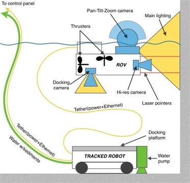
Communication between the robots and the control panel is based on a copper Fast Ethernet link. The power is supplied together with the communication by means of an underwater, neutrally buoyant, multi-conductor cable. The ROV can be connected directly to the control panel or to the tracked robot carrying an Ethernet switch.
3. Tracked robot
3.1. Design
The tracked robot is equipped with two track drive units by Inuktun Minitrac, intended for underwater operation. Usage of tracks has the main advantage over wheel drive that it may provide much better performance in terms of traction on a variety of surfaces. The track units feature elastomeric belts with treads, driven by DC motors. The robot chassis is based on an adjustable stainless steel frame that has mounting interfaces for inspection or cleaning equipment and watertight enclosure for control and power electronics. In Fig. 2, it is presented, equipped with a 3D sonar.
3.2. Kinematics
Mathematical model of the robot was created in order to appropriately implement control algorithms and path planning on the bottom of a tank. An initial step was to create a simplified model of a track drive. The elastomeric track was modelled as an inextensible tape wound on a driving sprocket and idler, similarly to the approach described in [7]. Next, the model of the track drive was integrated with a kinematic model of the entire robot.
Fig. 2Tracked mobile robot – prototype
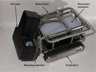
Fig. 3Velocities of the characteristic points during turning of the tracked robot
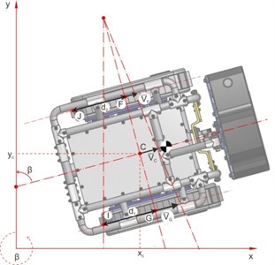
It was assumed that the robot will move on a flat and inclined surfaces. Kinematic equations were developed for a characteristic point of the robot (described as point C in Fig. 3), using similar approach to [7]. It was assumed that the robot moves on a planar surface, that may be inclined by angle of inclination with respect to the axis. The modeling of motion on inclined surface is limited to the case when the robot moves straight uphill or downhill as depicted in Fig. 5:
where is radius of the track drive sprockets, is the distance between the tracks, , are the slip ratios of track 1 and 2 respectively, , are angular velocities of the sprockets, -the heading angle of robot frame with respect to the axis and is the slope inclination with respect to horizontal surface
3.3. Dynamics
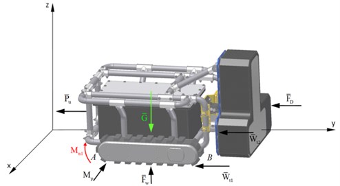
The model of the robot dynamics was created on the basis of Lagrange energetic methods. Initially, kinetic and potential energies were calculated in a way that each moving part of the system was analysed individually. Afterwards, total energies of track drive modules and frame assembly were combined to obtain total energy, taking into consideration all forces acting on a robot moving underwater, shown in Fig. 4.
Further calculations involved usage of Lagrange equations of the second kind. The final form of the dynamics model equations that include nonholonomic kinematic constraints is denoted by Eq. (2):
where is mass of the frame, is mass of the track, represents rolling friction force, is the cable pull force assumed as constant, is the buoyant force, is hydrostatic resistance force, are torques on the drive sprockets of tracks 1 and 2, is the moment of inertia of the robot frame, , are the reduced moments of inertia of the track drive module, is the moment of transverse resistance, represents the gravity force, is the drive efficiency and , , are the Lagrange multipliers (friction forces).
Fig. 4Forces acting on the robot during underwater locomotion
In the model it was assumed that the external forces such as rolling friction force, pull force, gravity force, buoyant force and hydrostatic resistance force are evenly distributed to calculate torques of both track drives. Validation of the mathematical model was conducted using a prototype of the robot. First of all, a mathematical model of the robot was implemented in Matlab/Simulink environment. A 3D path that involved avoiding an obstacle and climbing an inclined surface was set as an input for the simulation with maximum robot velocity. Further, the same path was followed by the prototype in the laboratory, on a test rig. The planned path is presented in Fig. 5. Resultant driving moments on each of the track drives were compared to the simulation results as presented in Fig. 6.
Fig. 5Trajectory of the robot for the simulation and experiment
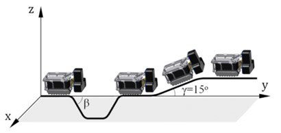
Fig. 6Driving moments on track drive motors – simulation and experiment
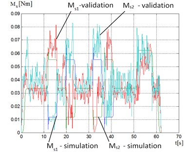
We observe that the values of moments obtained during validation agree with the values obtained during simulation, however multiple peaks are present even during motion with constant speed. This is caused by alternating changes of load carried by consecutive treads of the elastomeric tracks.
Further analysis of the signal confirmed that the frequency of track treads coincides with the peaks. This may be filtered to obtain much smoother plot.
4. ROV
4.1. Design
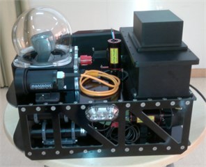
The ROV designed for the water tank inspection has two different tasks to perform: scan the surface of the tank walls under the water line and inspect the construction of ceiling and walls above the water line. It is equipped with two cameras to satisfy these tasks – a monochrome, high resolution camera, for photographing the surface of walls underwater, and a colour, low resolution, pan-tilt-zoom camera, used to navigate and inspect the ceiling and wall structure above water. Because of the way these cameras are mounted, which is the result of using the most of their functionality, an additional camera is needed to allow safe and easy docking on the tracked unit and avoid obstacles when submerging – this camera is located in the bottom part of the vehicle, looking downward. The high definition inspection camera is placed at the front of the robot in a watertight housing, equipped with a dome port to minimise image distortion due to air-water interface. The pan-tilt-zoom camera is placed perpendicularly to the inspection camera, in a watertight housing with a spherical dome, to fully utilise the camera's field of view when it rotates. It is at the top of the whole robot and can emerge from water when the robot surfaces. At the front of the mini-sub there are two high power LED light-heads with a beam angle of 120 deg. Some additional low power LED lights are located at both sides of the vehicle and the docking camera has its own. The vision system is complemented with four laser modules installed in a rectangular pattern, parallel to the high resolution camera's optical axis. The laser modules are encased in watertight housings with adjustable mounts. The red laser spots generated by these modules are used to measure distance and orientation of the inspected surface, calculate the image scale and remove perspective distortion from the images. Docking of the mini submarine is possible thanks to the use of the docking camera which allows to orient the robot correctly, looking at the illuminated marks on the tracked unit. Other important role of the docking camera is monitoring space under the robot to avoid collisions and entangling in the tether. To firmly connect the two units together there is an electromagnetic lock mechanism. The electric brushless thrusters move the robot horizontally and vertically. These two directions are separated. Two thrusters move the robot in surge and yaw. The central thruster moves the robot in heave. It is also used to keep the robot at a desired depth generating a small amount of thrust as the vehicle is designed to have slightly positive buoyancy to surface automatically in case of failure. Mini submarine has ballast tanks and electronics under the glass-fiber body. The ROV design is presented in Fig. 7 accompanied by a prototype photo in Fig. 8.
The control system of the ROV is based on two computing units - a real time micro-controller board and an embedded industrial PC, inertial and pressure sensors, brushless electronic speed controllers and the vision system which can play a double role of inspection and guidance. The real time unit is used for generating PWM waveforms, reading sensors and running time critical control loops. The industrial PC has a Linux based software architecture incorporating advanced control algorithms based on the vision system measurements. The control system is able to augment manual control of the ROV, done by the operator, with algorithms which support steady scanning of the water tank walls by keeping constant distance and attitude, important for building mosaics.
Fig. 7Design of the underwater remotely operated vehicle
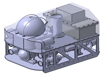
Fig. 8Photo of the prototype
4.2. Distance and attitude measurement
The primary task of the underwater inspection robot is scanning the surface of the tank walls in order to recognise and register defects (mainly cracks). To be able to measure objects of interests in the image, the distance to the surface and the robot attitude are needed. These data are not only useful for the photo measurements but also for the robot control system which has to automatically keep the robot moving at a desired distance, perpendicularly to the wall. Determining the position of the camera in reference to the scanned surface is possible thanks to the use of four parallel laser beams, casting spots on the photographed object.
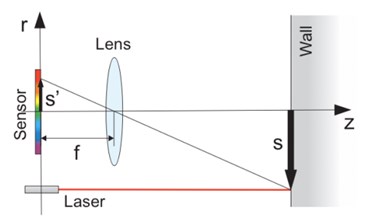
Fig. 9Formation of the laser dot image in the pinhole camera model. The image of the laser dot s is projected onto the camera sensor, through a lens with focal length f. The four parallel laser beams are located in a rectangular pattern of size a×b, symmetrically around the camera axis
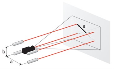
The beams are parallel to the optical axis and arranged in a symmetrical rectangular pattern. Only three spots are necessary to calculate distance and attitude. The redundant forth laser beam was introduced to increase robustness of the system, by allowing one spot to remain undetected or reject a detected outlier. There is always a risk that the laser beam will hit a crack or dent and the spot will be invisible or distorted. An important feature of the vision system is an underwater housing of the inspection camera equipped with a dome port, which minimises image distortion and gives maximum possible field of view. It allows for close object distance which decreases in-water light path and thereby improves image brightness and contrast [9].
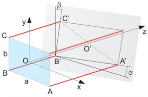
Fig. 10Geometry of the distance and attitude measurement
When a new image frame is captured it is then binarised and the centroids of the laser dots are calculated. Using Tales formula one can determine the distance to each dot using the following equations:
where denotes the distance from the optical axis to the laser dot determined by pattern size , and the same distance on image plane while is the focal length of the optical system. For clarity all those quantities are presented in Fig. 9. When the dot distances are known one can determine the distance along the optical axis by simple average and the attitude angles and (see Fig. 10) according to equations:
4.3. Experimental validation
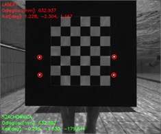
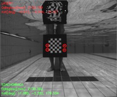
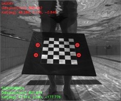
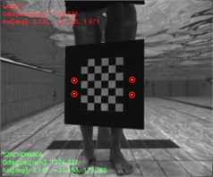
To validate the proposed measurement method, the robot was placed in a test tank, a calibration of the underwater vision system was carried out and a set of images was acquired for various distances and orientation of the calibration table representing the analysed surface. Results obtained by means of the calibration table were considered as reference results and were compared with measurements obtained by the developed vision algorithm. An application was developed using the OpenCV library, which can detect corners in the checkerboard pattern and calculate its distance and orientation in reference to the camera frame. The same software includes simple image processing and analysis algorithms which allow for the detection of the laser dot pattern projected onto the surface. The calculations based on the developed algorithm, presented above, are compared with the ground truth in real-time [10]. Some of the acquired images and results obtained during experimental tests are depicted in Fig. 11.
In an exemplary case for the object at a distance of 632.8 mm calculated from the reference calibration table, vision-laser based measured distance amounted to 632.9 mm (see Fig. 11(a)). At 2132.4 mm object’s distance, vision-based measured distance was 2152.2 mm (see Fig. 11(b)). When regarding exemplary calculation of two angles of rotation of the object: a) the angle of rotation about -axis amounted to 29.6 deg in the case of the reference measurement and 29.3 deg as a result of the developed vision-based measurement (see Fig. 11(c)); b) the angle of rotation about -axis 27.4 deg calculated using calibration table and 28.3 deg from vision-based measurement (see Fig. 11(d)).
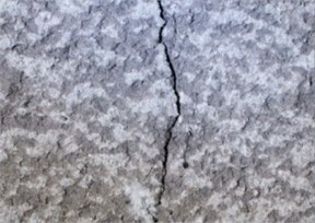
The image from the inspection camera is not only used on-line but also archived on a hard drive inside the robot. It is then used to assess the condition of the scanned walls by detecting mechanical defects like cracks. After downloading the images to the control panel they are processed by a multistage computer vision algorithm, designed to automatically detect cracks. Firstly, the images are calibrated and the perspective distortions are removed. Then the image is pre-processed to remove noise and analysed with region segmentation and morphological operations were employed to detect the cracks. An exemplary result of the crack detection algorithm on an image of a wall surface is shown in Fig. 12.
The developed crack detection algorithm will be extended by underwater by image processing and image enhancement methods [11-17] and the images will also be used for mosaicing [18-20] to create a panoramic view of the tank surface.
Other problems, like negative influence of ROV self-noise on detection aspect in water environment [21] or ROV control [22-25] will be considered as well.
Fig. 11Exemplary measurements in a test tank with our custom vision software: a) close, b) far, c) rotation about X-axis, d) rotation about Y-axis
a)
b)
c)
d)
Fig. 12Crack detection on the wall surface: a) input image, b) detected crack
a)
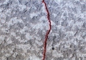
b)
5. Conclusions
The use of a complex system with high level of autonomy for the maintenance of fresh water reservoirs allows us to limit the time when the tanks are out of service. This is possible through regular monitoring with the use of a robot. Until now we had to do diagnostics in previously assumed periods. In addition, a robot equipped with a suction device can clean the bottom of the tank without disturbing its service. Another important feature of the system is the ability to perform 3D scans of underwater structures for diagnostic purposes and evidence.
Image processing and analysis algorithms dedicated to underwater mobile robots and ROVs were developed in this project. The first algorithm concerned measurements of robot position and attitude with respect to the analysed surface (i.e. surface of water tank). The proposed method is efficient and easy to implement so it can be used in a real time control system. The second algorithm deals with detection of wall surface defects, particularly cracks. Introduction of automatic inspection by a robot equipped with high resolution camera allows for quick tank condition assessment and can also be used for long-term health monitoring and maintenance planning by means of regular, repeatable checks [26]. Having a robotic system capable of measuring physical properties of identified defects (e.g. length of cracks) can lead to developing a kind of health factor for the whole tank.
The presented work was done in close cooperation and according to the guidelines of the Municipal Waterworks and Sewer Enterprise in Cracow (MPWiK S.A.).
References
-
VideoRay. http://www.videoray.com
-
Seabotix. http://www.seabotix.com
-
SAAB. http://www.seaeye.com
-
Australian National University. http://users.cecs.anu.edu.au/~rsl/sub/2-Systems/Submersibles.html
-
Woods Hole Oceanographic Institution. http://www.whoi.edu/page.do?pid=8423
-
Slingsby Engineering Limited. http://www.rov.net/pages/mrv1.htm
-
Ciszewski M., Buratowski T., Giergiel M., Malka Kurc P. K. Virtual prototyping, design and analysis of an in-pipe inspection mobile robot. Journal of Theoretical and Applied Mechanics, Vol. 52, Issue 2, 2014, p. 417-429.
-
Buratowski T., Ciszewski M., Giergiel M., Siatrak M., Wacławski M. Mechatronic Approach in Inspection of Water Supply Networks, Mechatronics – Ideas for Industrial Applications. Springer International Publishing, 2015, p. 447-454.
-
Jenkins F. A., White H. E. Fundamentals of Optics. Tata McGraw-Hill Education, 1981.
-
Kohut P. Mechatronics systems supported by vision techniques. Advances in Mechatronic Systems, Gdynia, Poland, Vol. 196, 2013, p. 62-73.
-
Schettini R., Corchs S. Underwater image processing: state of the art of restoration and image enhancement methods. EURASIP Journal on Advances in Signal Processing, Vol. 3, 2010, p. 14-15.
-
Ancuti C., Ancuti C. O., Haber T., Bekaert P. Enhancing underwater images and videos by fusion. IEEE Conference on Computer Vision and Pattern Recognition (CVPR), 2012, p. 81-88.
-
Iqbal K., Odetayo M., James A., Salam R. A., Talib A. Z. H. enhancing the low quality images using unsupervised colour correction method. IEEE International Conference on Systems Man and Cybernetics (SMC), 2010, p. 1703-1709.
-
Garcia R., Nicosevici T., Cufi X. On the way to solve lighting problems in underwater imaging, OCEANS, Vol. 2, 2002, p. 1018-1024.
-
Prabhakar C. J., Kumar P. U. P. An image based technique for enhancement of underwater images. arXiv.org, 2012.
-
Kohut P., Kurc K., Szybicki D., Cioch W., Burdzik R. Vision-based motion analysis and deflection measurement of a robot's crawler unit. Journal of Vibroengineering, Vol. 1, Issue 8, 2015, p. 4112-4121.
-
Ragulskis M., Aleksa A. Image hiding based on time-averaging Moire. Optics Communications, Vol. 282, Issue 14, 2009, p. 2752-2759.
-
Brown M., Lowe D. G. Automatic panoramic image stitching using invariant feature. International Journal of Computer Vision, Vol. 74, Issue 1, 2007, p. 59-73.
-
Szeliski R. Image Alignment and Stitching. Now Publishers Inc., 2006.
-
Singh H., Howland J., Pizarro O. Advances in large-area photo mosaicking underwater. IEEE Journal of Oceanic Engineering, Vol. 29, Issue 3, 2004, p. 872-886.
-
Listewnik K. Sound silencing problem of underwater vehicles. Solid State Phenomena, Vol. 196, 2013, p. 212-219.
-
Konieczny L., Burdzik R. Comparison of characteristics of the components used in mechanical and non-conventional automotive suspensions. Solid State Phenomena, Vol. 210, 2014, p. 26-31.
-
Burdzik R., Konieczny L., Adamczyk B. Automatic Control Systems and Control of Vibrations in Vehicles Car, Telematics – Support for Transport. Book Series: Communications in Computer and Information Science, Vol. 471, 2014, p. 120-129.
-
Młyńczak J. Algorithm Determining the Setting Force at Point Machines. Telematics – Support for Transport. Book Series: Communications in Computer and Information Science, Springer, Heidelberg, Vol. 471, 2014, p. 321-330.
-
Szymak P. Selection of method for underwater robot control. Solid State Phenomena, Vol. 164, 2010, p. 149-154.
-
Giergiel M., Buratowski T., Małka P., Kurc K., Kohut P., Majkut K. The project of tank inspection robot. Key Engineering Materials, Vol. 518, 2012, p. 375-383.
Cited by
About this article

The studies have been conducted under the Research Project No. R03005710 “Mechatronic Designing of Robots for Diagnostics and Maintenance of Tanks with Liquid”.
P. Kohut, P. Cieslak: concept and construction of ROV, concept and implementation of the vision-based measurement system, research and data analysis. M. Ciszewski, T. Buratowski: concept and construction of crawler robot, research. M. Giergiel: Concept of the whole system, substantive supervision, research.
