Abstract
The results of vibration measurements at characteristic points on the belt conveyor drive of bucket wheel excavatorSRs400 manufactured by Takraf are presented in the paper. The operating processes (transport of material on the belt conveyor) belong to the category of impacts, such as fitting, acceleration, sudden loading, and the like, which are extremely pronounced in mining machinery. For monitoring purposes, measurement was undertaken in all three directions, upon overhaul and after 11,850 hours of operation. Movement, speed and acceleration of oscillations were plotted using measured data and the effect of the rear connection of the electromotor mount support on its proper performance was determined.
1. Introduction
On bucket wheel excavators, the largest and most demanding mining machines, the drives, which have different functions, can be mounted in different ways. The excavated material is transported by means of rubber-belt conveyors. The conveyor drive is composed of an electromotor, gearbox, pulley (including their inter-linkages), braking mechanism, and structural supports on the excavator. All drive components need to feature adequate stiffness/strength to ensure that the system remains stable and reliable in operation.
With regard to the operation of a rubber-belt conveyor, the biggest problems occur in the structural supports of the drive due to wear and tear. The drive is connected to the steel boom of the excavator by means of a separable connection via axles. Two series of vibration measurements at characteristic points of the drive were undertaken to demonstrate the effect of the rear connection of the support on the drive and point out the technical problems of the drive in operation. The first series of measurements were conducted upon installation of a new drive assembly, and the second after 11,850 hours of operation, at the same characteristic points.
On a global scale, there are a number of papers that describe the effect of the dynamic behavior of the construction on the drive components. Some of them discuss the dynamic stability of the system and optimization of the geometry or design of the structure of the system [1-3]. Naprstek [1] indicates that the most frequently used dynamic stability analysis methods are related to individual dynamic systems that are widely discussed in various branches of engineering. From this perspective, the aim of that study was to present a brief review of the dynamic stability problem, its basic definitions and the principles, important phenomena, research motivations and applications in engineering. Luo and Tong [2] develop an efficient algorithm to find a moving is surface threshold level for evolving the design boundary and updating the weighting factor. The proposed algorithm coupled with commercial finite element analysis software is used to study optimal designs for vibrating structures. The obtained optimal designs were fabricated and the experimental tests conducted to validate the optimal topologies. Sinha [3] describe how optimal vibration absorbers are designed. The design procedure is quite generalized and can easily handle multiple modes of vibration. A general procedure for constructing a root loci plot is also developed. Numerical results are presented using a cantilever beam.
There are also papers that report research related to structural vibrations and their impact on the entire system [4, 5]. Xu et al. [4] originally formulated a slope vibration shape for damage detection in bars using longitudinal vibration shapes. A three-dimensional scanning laser vibrometer is used to measure the longitudinal steady-state response shape of an aluminum bar with damage due to reduced cross-sectional dimensions under harmonic excitation and the results show that the method can successfully identify and locate the damage. Slopes of longitudinal vibration shapes are shown to be suitable for damage detection in bars and have potential for application in noisy environments. Zhu and He [5] propose a vibration-based method that uses changes in the natural frequencies of a structure to detect the locations and extent of damage. It has the advantage of being able to detect various types of damage in the structure, including loosening of bolted connections. The developed damage detection method is experimentally validated on an aluminum three-bay space frame structure with L-shaped beams and bolted joints. Three types of introduced damage, including joint damage, member damage and boundary damage, were successfully detected.
Some papers address problems related to bucket wheel excavators and report experimental research [6-9]. Bošnjak, Savićević et al. [6] studied the engineering challenges that accompanied the process of returning the BWE from its post-accident state to the state of full operational readiness. Successful completion of a very delicate BWE rescue and balancing operation was followed by the reconstruction of a heavily damaged slewing platform. The redesign of the slewing platform structure produced favorable loads and stiffness distribution, while eliminating geometrical stress concentrators. Rusinski, Harnatkiewicz et al. [7] discuss a failure caused by a fractured shaft of the bucket wheel. An attempt was made to determine the causes of the bucket wheel shaft fracture. To that end, the character of changing loads and their maximum amplitudes was determined by performing measurements on the excavator. Also, Rusinski et al. [8] describe numerical and experimental identification of low frequency vibrations caused by operational loads of surface mining machines. The main goal was to investigate the relation between the vibrations of the complex multi-body structure of the machine and the operational loads. Based on the results, normal mode vibrations of separate parts of the bucket wheel excavator can influence the durability of the entire structure of the machine despite the fact that it vibrates at low frequencies. Bošnjak, Pantelić et al. [9] claim that the occurrence and propagation of cracks in the zones of slewing platform mantle holes probably lead to BWE collapse. The objectives of the study were to: diagnose the cause of cracks; design mantle reconstruction; and verify the reconstructed structure by numerical–experimental analysis.
Others discuss problems associated with belt conveyor drives, electromotors and diagnostics, most often based on vibrations [10-13]. Jovančić et al. [10] derive a methodological procedure for redesigning the shaft, gear box and bucket wheel. Measurements of vibrations at characteristic points of the gear box were used to validate the model. The data obtained in the frequency domain proved correctness. Maneski et al. [11] define a numerical-experimental procedure as a very suitable diagnostic tool. They show that the considered constructions failed due to incorrect operational parameters related to vibration of the structures. This enabled the determination of the actual structural behavior and reliable prediction of its response in operation, as well as the determination of the cause of unfavorable behavior or failure and assessment of the reliable service life and level of revitalization. Jin et al. [12] introduce a trace ratio linear discriminant analysis to deal with high-dimensional non-Gaussian fault data for dimension reduction and fault classification. Motor bearing data with single-point faults and generalized – roughness faults are used to validate the effectiveness of the proposed method for fault diagnosis. Ghorbanian and Faiz [13] deal with comprehensive concepts relating to faults that involve broken rotor bars in industrial induction motors. Since faulty motor behavior cannot be correctly identified without considering the operating condition of the motor, previous fault indicators are studied in-depth to investigate their applicability in different conditions.
The present paper examines the effect of the rear connection of the electromotor mount support on the proper operation of the electromotor that drives the rubber-belt conveyor of a bucket wheel excavator. Namely, the main objective is to point out the negative effect of the rear support (in operation) on the conveyor drive, due to its relatively large distance from the center of gravity of the electromotor.
2. Effect of high vibrations on electromotor as a result of poor condition of mount support
A bucket wheel excavator is a highly-complex dynamic system with a large number of vibration sources. It is sufficiently elastic and features different degrees of freedom/flexibility. The vibration excitation forces are either external or inherent in the system. Bucket wheel excavator forces are fully determined by the intensity of the excitation forces, the time interval in which they periodically occur, and the duration of their action. It is for this reason that vibrations are used to monitor and condition and behavior of the system (i.e. diagnostics).
In bucket wheel excavators, the drive assembly of the belt conveyor is commonly supported in one of the following ways:
– The gearbox and electromotor are mounted on a long beam, such that the structural support is far away from the center of gravity of the electromotor and the drive assembly is on the boom with which it moves. This particular case is shown in Fig. 1, which is a photograph of bucket wheel excavatorSRs400 (manufactured by Takraf, Germany) at Drmno open-pit mine (Kostolac Mining Basin, eastern Serbia). The insert in the figure shows the layout of the belt conveyor drive and the points at which vibrations were monitored.
– The gearbox and electromotor are on a short beam, such that the structural support is roughly below the center of gravity of the electromotor. The drive assembly is on the boom and moves along with it.
– The gearbox and electromotor are on a fixed mount – bottom beam of the excavator, which is a very stiff system in this case, and the boom with the belt conveyer moves independently.
Fig. 1Bucket wheel excavator. The insert shows a layout of the belt conveyor drive and the characteristic points where vibrations were monitored
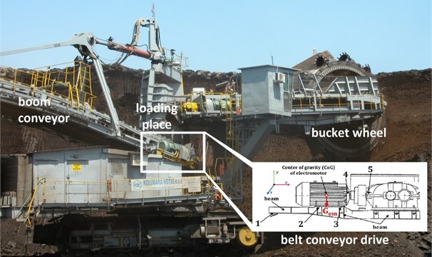
The characteristic points on the belt conveyor drive of the bucket wheel excavator, at which vibrations were monitored and which are shown in Fig. 1, are:
1) The rear support of the drive mount on the excavator boom;
2) The support of the electromotor on the drive mount (closer to the rear support);
3) The support of the electromotor on the drive mount (closer to the coupling);
4) The electromotor bearing; and
5) The gearbox bearing.
Both induced and natural vibrations occur in the drive assembly of the belt conveyor of the bucket wheel excavator. As is well known, induced vibrations are offset by balancing, via added or subtracted mass, by alignment, replacement of worn parts and adjustment of supports due to increased clearances. Natural vibrations are a structural effect, where a structure/component of the drive assembly acts as a signal amplifier at a sensitive frequency, or a frequency that cannot be characterized as a diagnostic parameter.
To prove a negative impact, primarily that of a worn rear support of the electromotor mount (increased clearance), which has an adverse effect on the overall performance of the drive (point 1 in the insert in Fig. 1), preventative vibration measurements are needed as soon as the excavator is put into operation after overhaul/installation (i.e. long before a structural clearance occurs), and then also after a clearance ensues. In the present case, measurement was undertaken after11850 hours of operation since overhaul/installation of the conveyor drive. To ensure validity of the results, nearly the same operating conditions of the excavator were specified and achieved in both measurement cycles. More precisely, in both cases:
– Coal was extracted from the upper cut (6 m-high vertical cuts);
– The kinematic conditions (excavator’s rate of travel, speed of movement of the super structure and excavator advance by the thickness of a cut) were identical;
– The parameters of the cuts (thickness 40 cm, width 25 cm) were the same;
– New bucket cutters were used; and
– The capacity and coal fragmentation were nearly identical.
The vibrations were measured by a three-component sensor capable of instantaneous sensing in three directions: transverse , vertical and axial . The instrumentation and data processing software were specially developed for this purpose by Mikro-Elektrika Co. from Belgrade. The instrumentation was comprised of a cutting-edge transducer, A/D converter, and USB-PC communication. The frequency signal was obtained applying a FFT (Fast Fourier Transformation) analysis. The software supports analysis of the time and frequency acceleration signal
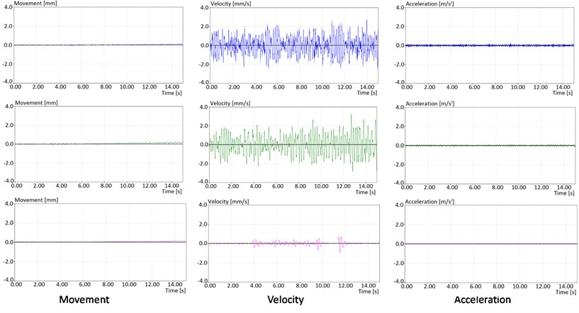
The results, that is, the vibrations in the time domain at the rear support of the drive mount on the excavator boom, are shown in Fig. 2.
Fig. 2Movement, velocity and acceleration, respectively, based on measurements conducted at the rear support of the drive mount on the bucket wheel excavator boom, at the beginning of operation after overhaul
3. Results and discussion
The diagrams shown below reflect the results of measurements conducted at the very beginning of operation of the conveyor drive after overhaul/installation. The color blue denotes vibrations in the transverse direction, green in the vertical direction, and red in the axial direction. Diagrams of movement, velocity and acceleration of oscillations were also produced, as shown. The results in Fig. 2 are typical of a reconstructed drive put into operation after overhaul, such that movement in all three directions is minimal, from 0.1 mm to 0.2 mm, or as much as allowed by the installation clearance of the connection between the drive mount and the steel structure of the boom. With this type of connection, the speed of movement is also very low, especially in the axial direction, which is indicative of both overall and local stiffness. Corresponding to such low velocities are minimal accelerations, from 0.1 m/s2 to 0.2 m/s2.
Vibration measurements in the time domain and in all three directions were repeated after 11850 hours of operation following overhaul/installation, also at the rear support. The color code is the same as in the case of measurements upon overhaul. Diagrams analogous to those shown in Fig. 2 were produced. Namely, Fig. 3 shows the measured vibrations over time at the rear support of the drive mount on the excavator boom after the said number of hours.
Fig. 3Movement, velocity and acceleration, respectively, based on vibration measurement at the rear support of the drive mount on the bucket wheel excavator boom after 11850 hours of operation since overhaul/repair
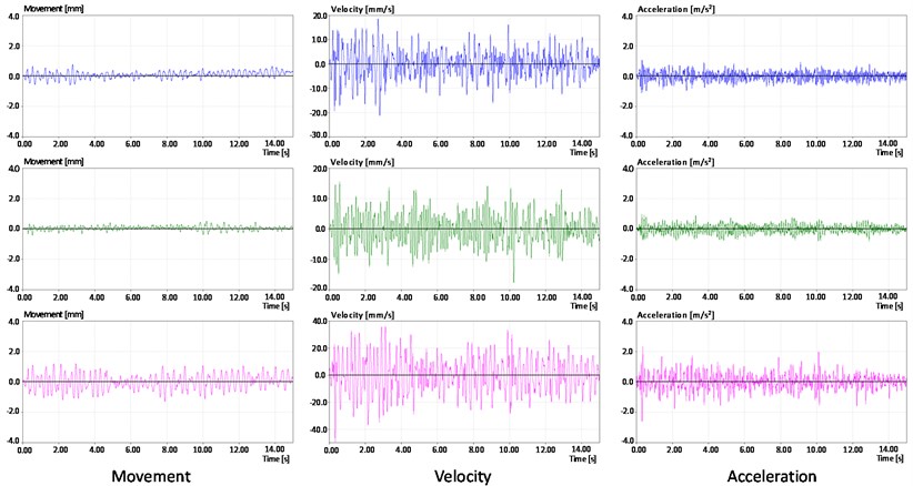
It is apparent by comparing Figs. 2 and 3 that the largest differences in the vibrations were registered in the axial direction ( axis/red). In other words, the drive mount support (connection via axles) had a greater clearance in the assembly after 11850 hours of operation, which intensified vibrations, particularly in the axial direction. The overall movement of the drive was caused, inter alia, by the movement of mass on the conveyor parallel to the drive center line (i.e. in the axial direction). This caused the support assembly to give way. The clearance was about 1.2 mm, which was the space within which movement occurred within the assembly. Table 1 shows the relations (quotients) of the recorded movement, velocity and acceleration, immediately after overhaul and after 11850 hours of operation.
In view of the fact that the data in Fig. 3 indicate that the highest vibrations were registered in the axial direction, Fig. 4 shows diagrams of acceleration vibrations over time in the axial direction at the characteristic points identified in Fig. 1.
The data clearly indicated that the support gave way in the axial direction. Slackening of the entire system was a result of a sudden increase in clearance and support failure/breakage. The reasons for this suggested the following:
–Measurement point 1 in Fig. 1 was quite distant from the center of gravity of the electromotor and caused the elasticity of the support to increase and the stiffness levels to differ;
–Point 1 was common to two different dynamic systems: drive with mount and belt conveyor boom. These two systems had different dynamic relationships with the support. Point 1 was the point of interaction of two different dynamic systems – the drive and the boom.
Table 1Correlations between maximum values based on vibration measurements at the beginning of operation of the bucket wheel excavator after overhaul, and following 11850 hours of operation
Movement [mm] | Velocity [mm/s] | Acceleration [m/s2] | |||||||
Direction | |||||||||
Beginning of operation | < 0.2 | < 0.2 | < 0.2 | 2-2.5 | 2-3 | 0.5-1 | < 0.2 | < 0.2 | < 0.2 |
After 11,850 hours of operation | 0.5-0.7 | 0.2-0.4 | 1-1.2 | 10-20 | 10-17 | 20-40 | 0.5-1 | 0.3-0.8 | 1-2.2 |
Relation | 3.5x | 2.0x | 6.0x | 8.0x | 5.7x | 40.0x | 5.0x | 4.0x | 11.0x |
Fig. 4Measured acceleration vibrations in the time domain, in the axial direction, at characteristic points of the drive after 11850 hours of operation
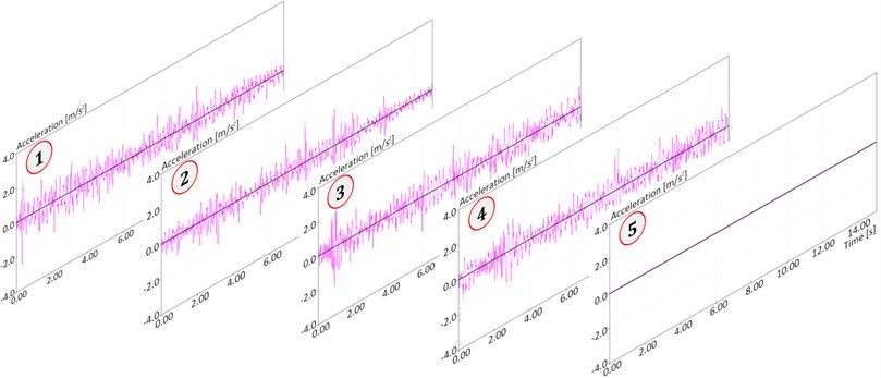
The first four measurement points delivered more pronounced signals in the axial direction that the last (fifth) point. At the fifth point, which is the bearings at the gearbox inlet, the signal in the axial direction was not strong and indicated that the stiffness of the gearbox was much higher than that of the other components. Also, the presence of a flexible coupling between the electromotor and the gearbox prevented transmission of axial movement.
Fig. 5 shows the signals measured in the frequency domain at the five characteristic points of the drive.
Fig. 5Vibration acceleration in the frequency domain at characteristic points on the conveyor drive after 11850 hours of operation
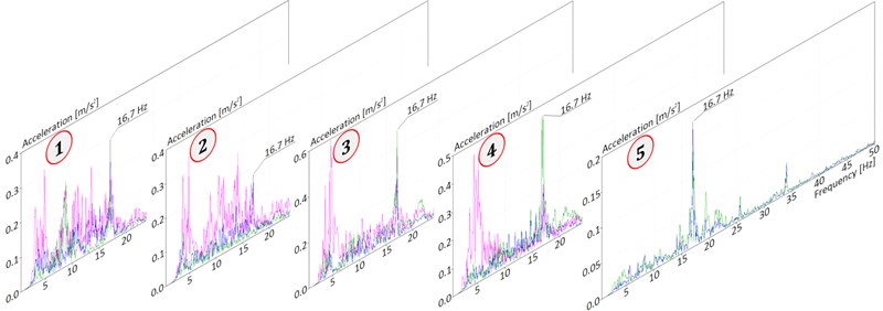
Vibration measurements conducted on the belt conveyor drive of the bucket wheel excavator after 11850 hours of operation revealed the following dominant frequencies:
1) Frequencies 3.1 Hz, 3.6 Hz, 4.1 Hz and 4.8 Hz were registered at the first four characteristic points, but not the fifth (gearbox). The amplitude was from 0.3 m/s2to 0.6 m/s2 (all the frequencies were pronounced in the axial direction). These low frequencies were associated with the drive mount, or the rear support on the boom (due to poor condition of the rear connection). This behavior was generally the result of the way the drive mount was suspended on the boom, but also of loading of large pieces of coal. Low frequencies that coincided with natural frequencies of the mount were a result of bending and twisting of the drive support. The amplitudes increased because of the increased clearance in the support on the boom. More precisely, the measured dominant frequencies overlapped with the initial natural forms of oscillation. Low frequencies had an extremely negative effect on the supporting steel structure.
2) The frequency of 16.7 Hz originated from excitation (electromotor RPM was 1000 min-1) and this signal was recorded at all measurement points. The amplitude was from 0.2 m/s2 to 0.45 m/s2 (all excitation frequencies were pronounced in all three directions, except at the fifth measurement point – gearbox inlet – where the dominant directions were vertical and transverse). The values were still not alarming from an operational safety perspective but indicated future problems. There will always be an excitation frequency, but it might have an upward trend depending on the condition of the system and decreasing stiffness.
Due to the existence of a very small installation clearance (and often an interference fit as well), the drive mount of the belt conveyor of the bucket wheel excavator in essence played the role of a dynamic sink. The overall dynamic behavior of a drive assembly, especially of the electromotor, can be affected by any disruption of this connection. The proposed solution in this specific case is to shorten the mount of the drive assembly, such that the rear support (point 5 on Fig. 1) enters the structure of the boom below the center of gravity (point in the insert in Fig. 1) of the electromotor. This would reduce the flexibility of the mount, increase stiffness and avoid any inadequate dynamic effect on the electromotor.
If the high amplitudes resulting from the increasing intensity of the interfering force or decreasing dynamic stiffness (which is the case here) indicate the magnitude of the problem, a proper distribution of supports and increase in dynamic stiffness can lead to an optimal solution. If the amplitude is an indicator of the magnitude of the problem, due to increased intensity of the interfering force or reduced dynamic stiffness, as in the present case, a proper distribution of supports and an increase in dynamic stiffness might be the optimal solution. It is generally not possible to reduce the intensity of the interference due to the pre-defined production process or the design of the load-bearing structure and its overall dynamic behavior.
4. Conclusions
The way in which a drive assembly is supported has the greatest effect on the proper operation of the belt conveyor of a bucket wheel excavator. The present research showed that the drive assembly was not properly supported on the unloading boom of the studied bucket wheel excavator and that elevated vibrations had an adverse effect on drive performance.
In difficult operating conditions, it is the electromotor of a bucket wheel drive that usually fails. As the power of the electromotor increases, so does the possibility of failure. Intensified dynamic processes of a bucket wheel excavator are most often caused by high mechanical or thermal stress, and in some cases also by increasing safety concerns.
Practice has shown that certain components of the drive assembly of a bucket wheel excavator are permanently loaded due to operational dynamics. Special attention was devoted to the way the electromotor mount was supported on the structure of the unloading boom of the bucket wheel excavator. In other words, one of the obvious potential reasons for electromotor failure is an inadequate geometry of the mount and the way it is supported.
The effect of slackening of the support on the performance of the electromotor can be diagnosed by measuring vibrations. As stiffness is reduced, the vibration amplitude will increase to the point of failure. Failure can be prevented by proactive monitoring.
Namely, the operation of the electromotor is intermittent (frequent consecutive starts and highly-variable loading – from idle to overload). This tends to cause cracks or fractures in the electromotor cage, degradation of insulation, bearing failure and increased vibrations. Consequently, in the case of asynchronous electromotors, the nature of the load determines the mechanical conditions but so does the way in which the mount is supported on the unloading boom of a bucket wheel excavator.
References
-
Náprstek J. Combined analytical and numerical approaches in Dynamic Stability analyses of engineering systems. Journal of Sound and Vibration, Vol. 338, 2015, p. 2-41, https://doi.org/10.1016/j.jsv.2014.06.029.
-
Luo Q., Tong L. Optimal Designs for vibrating structures using a moving isosurface threshold method with experimental study. Journal of Vibration and Acoustics, Vol. 137, Issue 6, 2015, p. 061005, https://doi.org/10.1115/1.4030771.
-
Sinha A. Optimal damped vibration absorber: including multiple modes and excitation due to rotating unbalance. Journal of Vibration and Acoustics, Vol. 137, Issue 6, 2015, p. 064501. https://doi.org/10.1115/1.4030714.
-
Xu W. W., Zhu W. D., Smith S. A., Cao M. S. Structural damage detection using slopes of longitudinal vibration shapes. Journal of Vibration and Acoustics, Vol. 138, Issue 3, 2016, p. 034501, https://doi.org/10.1115/1.4031996.
-
Zhu W. D., He K. K. Detection of damage in space frame structures with: shaped beams and bolted joints using changes in natural frequencies. Journal of Vibration and Acoustics, Vol. 135, Issue 5, 2013, p. 051001, https://doi.org/10.1115/1.4024393.
-
Bošnjak S., Savićević S., Gnjatović N., Milenović I., Pantelić M. Disaster of the bucket wheel excavator caused by extreme environmental impact: consequences, rescue and reconstruction. Journal of Engineering Failure Analysis, Vol. 56, 2015, p. 360-374. https://doi.org/10.1016/j.engfailanal.2015.01.002.
-
Rusinski E., Harnatkiewicz P., Kowalczyk M., Moczko P. Examination of the causes of a bucket wheel fracture in a bucket wheel excavator. Journal of Engineering Failure Analysis, Vol. 17, Issue 6, 2010, p. 1300-1312, https://doi.org/10.1016/j.engfailanal.2010.03.004.
-
Rusinski E., Moczko P., Pietrusiak D. Low frequency vibrations of the surface mining machines caused by operational loads and its impact on durability. Conference Proceedings, International Conference on Noise and Vibration Engineering ISMA, KU Leuven, Heverlee, Belgium, 2014, p. 683-694.
-
Bošnjak S., Pantelić M., Zrnić N., Gnjatović N., Đorđević M. Failure analysis and reconstruction design of the slewing platform mantle of the bucket wheel excavator O&K SchRs630. Journal of Engineering Failure Analysis, Vol. 18, 2011, p. 658-669, https://doi.org/10.1016/j.engfailanal.2010.09.035.
-
Jovančić P., Ćelovićš, Ignjatović D., Maneski T. Redesigning components of power transmission 10according to numerical model and vibration diagnostics. Journal of Vibroengineering, Vol. 15, Issue 3, 2013, p. 1322-1329.
-
Maneski T., Jovančić P., Ignjatović D., Milošević Mitić V., Maneski M. Condition and behaviour diagnostics of drive groups on belt conveyors. Journal of Engineering Failure Analysis, Vol. 22, 2012, p. 28-37, https://doi.org/10.1016/j.engfailanal.2012.01.001.
-
Jin X. H., Zhao M. B., Chow T. W. S., Pecht M. Motor bearing fault diagnosis using trace ratio linear discriminant analysis. IEEE Transactions on Industrial Electronics, Vol. 61, 2014, p. 2441-2451, https://doi.org/10.1109/TIE.2013.2273471.
-
Ghorbanian V., Faiz J. A survey on time and frequency characteristics of induction motors with broken rotor bars in line-start and inverter-fed modes. Journal of Mechanical Systems and Signal Processing; Vols. 54-55, 2015, p. 427-456, https://doi.org/10.1016/j.ymssp.2014.08.022.
About this article

This article is a contribution to Projects TR035040 and TR033039 funded by the Serbian Ministry of Education and Science.
