Abstract
The new type of the reversible, vibratory conveyor in which a smooth velocity control (within the full range) in both directions is possible, is presented in the hereby paper. In order to investigate the correctness of the machine operation at first the physical model of the conveyor with a feed was constructed and then its mathematical model was developed. Simulations were performed for the eight-layer feed material in five columns. The obtained simulation results confirmed the proper operations of the conveyor.
1. Introduction
Vibratory conveyors allowing feed transportation in two directions [1, 2], as well as the ones in which it is possible to control the feed transport rate [3], are applied in some production lines. The author developed previously the original solution of the reversing vibratory conveyor [4] but it had several faults which in the new solution are omitted. Several solutions of two-way conveyors can be found in the industry, while the control of transporting rate is the most often realised by the change of the rotation velocity of forcing vibrators. This type of solution can be easily realised, however it carries a risk that the system will enter into the resonance zone. There are also several studies concerning the feed transport rate.
1.1. Current solutions of the two-way vibratory conveyors
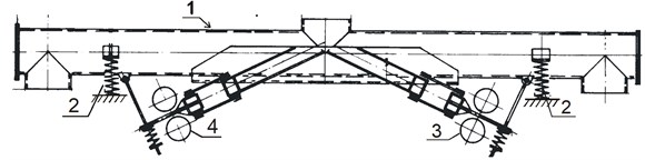
Two-way vibratory conveyors of various kinds are currently produced. The solution the most often applied is the system with three vibrators (Figs. 1, 2) [2, 5] or similarly operating vibrator with two separate systems of vibrators (Fig. 3).
Fig. 1Two-way conveyor of the Scan-Vibro Company [2]
![Two-way conveyor of the Scan-Vibro Company [2]](https://static-01.extrica.com/articles/17257/17257-img1.jpg)
Fig. 2Two-way conveyor of the Eralki Company [5]
![Two-way conveyor of the Eralki Company [5]](https://static-01.extrica.com/articles/17257/17257-img2.jpg)
In order to obtain transport in the required direction in conveyors presented in Figs. 1 and 2, vibrators 3 and 5 (transport to the right) or vibrators 4 and 5 (transport to the left) are put into operation. The transportation direction is caused by the proper direction of trough vibrations 1 on the suspension 2.
Fig. 3Two-way conveyor of the Jost Company
In the conveyor shown in Fig. 3, electric motors drive shafts with an unbalanced mass mounted to them. This mass forces vibrations perpendicular to the line passing through the axes of the vibrators system (3,4) and at a certain angle to the conveyor trough (1) suspended on the springs system (2). In dependence of the required transport direction of a material, alternatively either the first or the second system of vibrators is put into operation. Conveyors shown in Fig. 1, 2 and 3 are characterised by a high yield, similar to the conveyors transporting in one direction only but are very expensive in production and maintenance. Working vibrations of one system of vibrators cause in bearings of the other system (not operating in the moment) grease squeezing and occurrence of false Brinneling, which leads to very fast wearing of bearings. A long time needed for changing the transport direction, related to the coasting time of the first system of vibrators and the starting time of the second system, constitutes a serious flaw of this solution.
Two-way conveyors of one vibrator (4) centrally suspended, near the conveyor centre of gravity, to the trough (1) suspended on the springs system (2) are also known (Fig. 4) [6].
Fig. 4Two-way vibratory conveyor US 6029796 2000 [6]
![Two-way vibratory conveyor US 6029796 2000 [6]](https://static-01.extrica.com/articles/17257/17257-img4.jpg)
A vibrator is equipped with a motor of variable directions of rotations. The force originated by the vibrator is transmitted to the trough by suspension system 3. This suspension is tuned in such a way as to have the system operating at the axial direction (horizontal), near the resonance frequency increasing trough vibrations in the horizontal direction while not changing them in the vertical direction. This flattening of the characteristic allows to transport the feed without transmitting to it large dynamic forces during collisions with the trough, which is especially important at transporting delicate and fragile elements. Very low efficiency of such transport is a fault of this type of conveyors. Another essential fault of this solution is the way of changing the transport direction, which is done by changing the rotation direction of the forcing vibrator and - in consequence – a long time needed for its realisation. The change of the motor rotations direction requires passing through the machines successive transient resonances.
Another group of solutions constitute conveyors with the mechanical change of the transport direction performed either by manual or automatic change of the suspension angle of the drive vibrators system, causing the change of the trough vibrations direction, e.g. patent Baker of the Carrier Vibrating Equipment Company [7].
2. Description and the principle of operation of the new conveyor solution
The subject of the analysis constitutes the vibratory conveyor (Fig. 5) of a controlled transport velocity with the possibility of reversal operations, applied for transporting of loose materials or objects of small dimensions with a variable transport velocity and in the selected direction [8]. The main aim of the invention is developing the new, improved two-way feeder or conveyor in which the transport direction and velocity can be changed very fast.
Fig. 5Schematic presentation of the conveyor acc. to the invention: M, J – mass and moment of inertia of the trough of the vibratory conveyor, kx, ky, bx, by – stiffness and damping of the suspension of the conveyor through, mw, ew, Jw – mass, unbalancing and moment of inertia of the drive vibrator, ks, bs – stiffness and damping of the suspension of Frahm’s eliminators m1,2
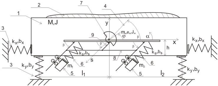
The vibratory conveyor, according to the invention, has the trough (in a similar fashion as in the described above solutions) open on both ends (1), elastically supported (3) on the stiff base in an essentially horizontal placement. It is equipped with one vibratory drive (7), due to which there are no problems related to self-synchronisation of several drives [9, 10]. This drive (7) is centrally suspended to the trough near the centre of gravity of the conveyor. Two or more Frahm’s eliminators, each consisting of additional masses , (5) suspended on springs (6) to the trough, are connected with the conveyor trough. These eliminators of vibrations have the same natural frequencies and are symmetrically, in pairs, situated on both sides of the shaft axis, while their masses are guided along parallel (to each other) directions (4) deviated from the level by the angle (9) adjustable within a range of 180° from the level.
The principle of operation of this conveyor is based on the fact, that when the vibrator (7) excitation frequency at the steady state satisfies an equation:
where masses and (which in the simplest case are equal as well as their suspension stiffness , then the system is symmetric and minimises angular vibrations of the trough) vibrate with an amplitude triggering – in springs – the counter-forces to the vibrator excitation force in the axial direction of springs . At small damping in springs – according to the Frahm’s eliminator principle – this causes damping of the trough vibrations at the direction deviated from the level by the adjustable angle [11, 12]. Depending on the direction of the trough vibrations, the feed (2) transport can proceed with various velocities in the selected direction. This solution enables fast changing of the feed displacement velocity and direction by changing the angle of Frahm’s eliminators. The obtained trough vibrations have a character close to rectilinear. At changing the transport direction, the system is not passing through resonance zones, which is highly advantageous. This problem is theoretically analysed in paper [9], while the practical problems of the passage through resonance are described in papers [13, 14].
2.1. Model of the developed conveyor loaded with feed
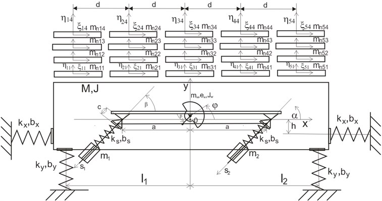
In order to verify the correctness of operations of the proposed conveyor the computer simulation of the system presented in Fig. 6 was performed. The simulation model developed for verifications of analytical solutions takes into account an influence of the machine body collisions with feed as well as allows to determine the material transport velocity in both directions.
The conveyor loaded with feed constitutes the system to be modelled. There are several papers related to the feed behaviour on vibrating surfaces theoretically [15] and practically [16, 17], however the feed model presented in work [18] was applied in the hereby paper.
The conveyor model consists of the inertial vibrator of a variable eccentric of unbalanced mass and the independent inductive drive (described by means of the static characteristic), the machine body performing a plane motion and supported on the system of vertical coil springs and five four-layered models of loose feed [14] distributed in various points of the machine working surface.
Fig. 6Model of the conveyor together with the feed: mnjk – mass of the elementary feed, ηjk, ξjk – axles of the system related to two degrees of freedom of the elementary mass mnjk
2.2. Mathematical model of the developed conveyor loaded with feed
The mathematical model of such system consists of the matrix Eq. (2) describing the machine motion, Eq. (10) providing the electromagnetic moment of the drive motor, Eq. (9) used for the determination of motion of successive feed layers [19] and dependencies Eqs. (7), (8) describing normal and tangent interactions between feed layers and between feed and the machine body. Forces related to elasticity and damping as well as forces originated from the lowest feed layer (friction and pressure ), which influence the trough, are occurring in the right member of the equation in vector . In the matrix Eq. (3) elementary feed masses are not included because they move according to Eq. (9) and have influence on the main mass only by friction and pressure. The other way round the movement of the trough has influence on the elementary feed masses:
where: – normal component of the th layer contact force acting on in the th column, – tangent component of the contact force originated from friction of the th layer with in the th column, – material layer index, 0 concerns the machine body, – index of the material layer column.
When the successive feed layers (in the given column) and are not contacting, the contact force in the normal and tangent direction in between these layers equals zero:
Otherwise, there is the contact force between feed layers , and , (or between the first layer and the trough) in the normal direction and its model [10] is of a form:
and the contact force originated from friction in the tangent direction:
where: and – Herz-Sztajerman constants, – coefficient of restitution of normal impulses at collisions.
Equations of motion in directions and of individual feed layers, with taking into account the conveyor interactions with bottom feed layers, are of a form:
– electromagnetic moment assumed in the form corresponding to the static characteristic of the motor:
where: – stalling torque of the drive motor, – synchronous frequency of the drive motor, – stalling frequency of the drive motor.
The simulation of the system presented in Fig. 6 was for the following values of parameters: 1 m, 0 m, 50 Ns/m, 75000 N/m, 60 Ns/m, 444132 N/m, 18 kg, 120 kg, 10 kg, 0.0001 kgm2, 25 kgm2, Variable, 0.05, 0.4, 1, 0.215 m, 50 Nm, 42.5 rad/s, 27 rad/s.
2.3. Simulation results
All simulations were performed for eight feed layers, which – as revealed in paper [20] – fully reflects the real feed. The more layers the more precise simulation of the feed movement. On the basis of the paper [20] and on the author’s own experience it can be stated, that when there are more than 4 layers the feed behaviour images the reality well and when there are more than 8 layers there are in practice no differences. It should be mentioned that layers cannot interpenetrate in the simulation. Already in the sixties in the paper [21] it was experimentally shown that feed layers are not interpenetrating during transport.
The simulated system had 5 columns of feed. When in the simulated system rotational vibrations of a trough around the alpha angle occur the number of columns is essential, however when in the simulated system vibrations are rectilinear all columns are moving with the same velocity and thus their number is not important.
An influence of the restitution coefficient was not analyzed in this paper. Its change influences – to a low degree only – the transport velocity, while will not influence a character of this velocity in dependence of the setting angle of eliminators [11]. At such number of feed layers the occurring damping causes that the collision can be treated as the elastic one.
Fig. 7Example of the trough and feed motions during the transportation
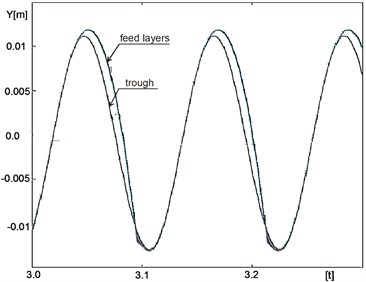
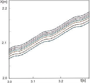
Fig. 8Example of displacement of eight layers of the feed in the horizontal direction
The example of the feed motion during its transportation is shown in Fig. 7. From the point of view of the hereby presented solution of the conveyor the most important is, in practice, the velocity and direction of the feed transportation.
The example of the feed motion during its transportation in the horizontal direction is shown in Fig. 8.
In order to determine the average transportation velocity of elements , several simulations were performed for various angles, each time measuring the transportation velocity. The diagrams in Fig. 9 and 11 are the results of these simulations.
Fig. 9 presents the dependence of the feed transport velocity for the whole range angles.
As can be seen in Fig. 9, at the setting angle or 180 the feed transport occurs regardless of nearly horizontal vibrations of the trough. This results from the unbalanced mass rotations and – in consequence – from small circular motions of the trough (Fig. 10). At such setting of eliminators the conveyor operates in a similar fashion as the conveyor of the General Kinematic Corporation presented in Fig. 5. The feed at this settings of the angle transport is not very fast in these both conveyors however the good point of the presented setting is the fact that impact forces transmitted to transported elements are quite small.
Fig. 9Transport velocity in dependence of the setting angle of vibrators. The direction of the unbalanced mass rotation in accordance with the clock hands movement
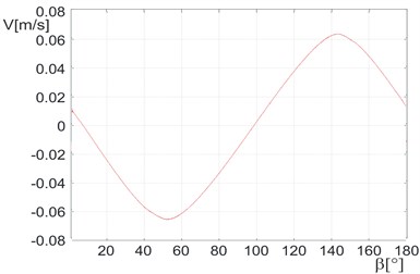
Fig. 10Dependence of the vertical vibrations on horizontal ones for β= 0°. The direction of the unbalanced mass rotation in accordance with the clock hands movement
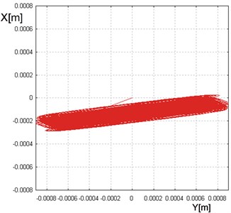
Fig. 11Dependence of the transport velocity in dependence on the setting angle of vibrators. The direction of unbalanced mass rotation is opposite to the clock hands movement
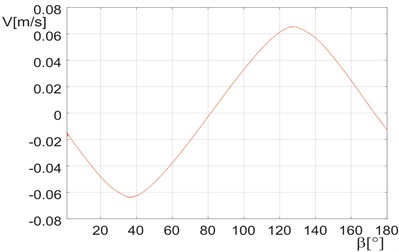
Fig. 11 presents the dependence of the feed transport velocity at the opposite direction of the unbalanced mass rotation (for various angles). Fig. 9 and 11 show that in dependence of the angle position the transport velocities can be controlled within the whole range and in both directions.
In case of Figs. 9 and 11, which are of a similar character, it can be seen that they are shifted in phase. This is the result of the rotation direction of the inertial vibrator and in consequence of different velocities at extreme values, e.g. for 0 or for 180.
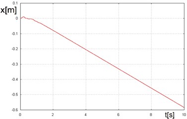
Figs. 12 and 13 present vibrations of the trough for the maximum of the transport velocity in both directions, while in Figs. 14 and 15 the dependence of the feed displacement for these velocity values is shown as a time function.
Fig. 12Dependence of the vertical vibrations on the horizontal ones for β=128°. The direction of the unbalanced mass rotation in accordance with the clock hands movement
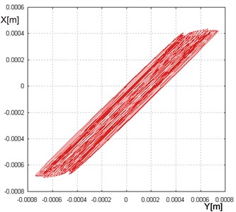
Fig. 13Dependence of the vertical vibrations on the horizontal ones for β= 38°, The direction of the unbalanced mass rotation in accordance with the clock hands movement
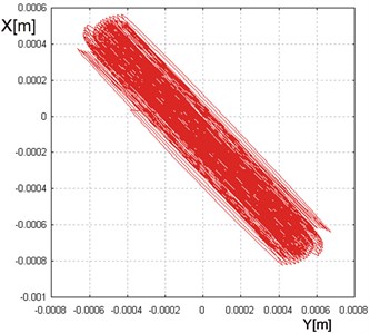
Fig. 14Dependence of the feed displacement as the time function, for β= 128°. The direction of the unbalanced mass rotation in accordance with the clock hands movement
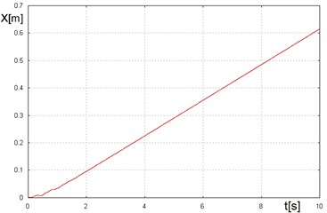
Fig. 15Dependence of the feed displacement as the time function, for β= 38°. The direction of the unbalanced mass rotation in accordance with the clock hands movement
As can be seen, at the proper setting of the beta angle, it is possible to obtain a high transportation velocity of feed in both directions, in a similar fashion as in classic conveyors. These velocities are not the same in both directions, due to the rotation direction of the inertial vibrator. At the reversal rotation of the vibrator values of the maximal velocities will be also different, moreover their maximal values will be interchanged. It means that a higher velocity will be achieved at transporting to the left.
3. Conclusions
Vibratory conveyor of a controlled transport velocity and with a possibility of reversal operations has a simple and reliable structure.
Vibratory conveyor of the proposed structure provides the possibility of a fast change of the feed transport velocity and direction.
There is the possibility of such conveyor operation, which enables the transport at small impact forces transmitted from the throw to the feed.
References
-
Musschoot A. Two-Way Vibratory Conveyor. US Patent No. 6029796, 2000.
-
www.directindustry.com
-
Rosenstrom R. Reversing Natural Frequency Vibratory Conveyor System. US Patent No. 6298978, 2001.
-
Czubak P. Equalization of the transport velocity in a new two-way vibratory conveyor. Archives of Civil and Mechanical Engineering, Vol. 11, 2011.
-
www.eralki.com.
-
www.skala.com.au.
-
Baker S. Vibratory Drive System for a Vibratory Conveyor Apparatus. US Patent No. 5064053, 1991.
-
Czubak P. Vibratory Conveyor with the Controlled Transport Velocity with the Possibility of Reverse Operation. Patent Application No. P-410 204, 2014.
-
Blechman I. Vibration Mechanic. Fizmatlit, Moscow, 1994.
-
Wang D., Zhao C., Yao H. Vibration synchronization of a vibrating system driven by two motors. Advances in Vibration Engineering, Vol. 11, Issue 1, 2012, p. 59-73.
-
Czubak P. Reduction of forces transmitted to the foundation by the conveyor or feeder operating on the basis of the Frahm’s eliminator, at a significant loading with feed. Archives of Mining Sciences, Vol. 57, Issue 4, 2012, p. 1121-1136.
-
Klemiato M., Czubak P. Event driven control of vibratory conveyors operating on the Frahm’s eliminator basis. Archives of Metallurgy and Materials, Vol. 60, Issue 1, 2015, p. 19-25.
-
Czubak P. Analysis of the new solution of the vibratory conveyor. Archives of Metallurgy and Materials, Vol. 58, Issue 4, 2013, p. 1037-1043.
-
Michalczyk J., Czubak P. Methods of determination of maximum amplitudes in the transient resonance of vibratory machines. Archives of Metallurgy and Materials, Vol. 55, Issue 3, 2010, p. 695-705.
-
Hor E. L., Linz S. J. Model for transport of granular matter on an annular vibratory conveyor. Journal of Statistical Mechanics – Theory and Experiment, 2005, p. L02005.
-
Guillermo R., Soto-Yarrritu, Martinez A. Computer simulation of granular material. Vibrating Feeders, Powder Handling and Processing, Vol. 13, Issue 2, 2001.
-
Rouijaa M., Kruelle C., Rehberg I., Grochowski R., Walzel P. Transport and pattern formation in granular materials on a vibratory conveyor. Chemical Engineering and Technology, Vol. 28, 2005, p. 41-44.
-
Michalczyk J. Phenomenon of force impulse restitution in collision modelling. Journal of Theoretical and Applied Mechanics, Vol. 46, Issue 4, 2008, p. 897-908.
-
Michalczyk J., Czubak P. Influence of collisions with a feed material on cophasal mutual synchronisation of driving vibrators of vibratory machines. Journal of Theoretical and Applied Mechanics, Vol. 48, Issue 1, 2010, p. 155-172.
-
Michalczyk J., Cieplok G. Numerical model of vibrating screen. Modelowanie Inżynierskie, Vol. 1, Issue 32, 2006, (in Polish).
-
Czubak A. Wibratory Conveyors. Ślask, Katowice, 1964, (in Polish).
Cited by
About this article

