Abstract
The study presented in this paper deals with the dynamics of a straight supported pipe conveying a harmonically pulsating incompressible fluid flow. It is assumed that the motion is planer and the pipe is normally horizontal, and there is a leakage from the pipe at a certain point and this leakage causes a repeated impulse forces acting on the pipe response. The pipe is fixed by two identical supports of three different types chosen for the sake of comparison. The first two supports are rigid, the second two are of conventional flexible type and are represented by springs and dampers while the third two supports are of Magnetorheological type and are represented by MR dampers. The variation of flow velocity and fluid pressure along the pipe is taken into consideration. The effect of leakage position and its amount on the dynamic performance and vibrations of the pipe is studied. The detection of leak location along the pipe is studied numerically using the spectrum analysis. The influence of supporting type and pulsating frequency on the pipe response is investigated. The effect of input voltage to the MR damper is also taken into consideration.
1. Introduction
In many situations where machines are operating and fluids are transported, pipe systems are responsible for the transmission of noise, for example in buildings, ships, power plants and process plants. Moreover, pipe systems are a critical factor in the reliability of systems. Excessive vibrations may lead to fatigue and cause damage to vital parts of installations. Fluid pulsations may also cause high vibrations and incorrect reading of flow meters and other control devices. On the other hand, the leakage of fluid from pipes causes impulse forces which cause vibrations acting on the pipe. The monitoring of pulsations or vibrations can be valuable to diagnose malfunction of machinery.
Over the past sixty years’ extensive studies have been carried out on dynamic analysis of pipeline systems subjected to supporting conditions and loading.
Notable contributions in this area include the works of Chen [1] and Paidoussis [2, 3]. Nikolie and Rajkavi [4] introduced a dynamic model of nonlinear pipes conveying pulsating fluid with different types of supports. Folley and Bajaj [5] considered nonlinear spatial dynamic characteristics of cantilever pipes conveying fluid. Jensen [6] analyzed dynamic behaviors of vibrating pipe containing fluid subject to lateral resonant base excitation using the perturbation method of multiple scales.
Jeong et al. [7] proposed a finite element model of pipes conveying periodically pulsating fluid and analyzed the influence of fluid velocities on pipe’s stability.
Shen et al. [8] studied the band gap properties of the flexural vibration for periodic pipe system conveying fluid using the transfer matrix method. These methods have proved suitable for analyzing flow-induced vibration of certain pipes. Lee et al. [9]studied the transient (water hammer) signals for the detection of leaks in pipeline systems. A pressure transient travels along the system at high speed and is modified by the system during its travel. Also they discussed and provided possible solutions to a number of practical issues associated with leak detection methods of this type, including the impact of the system configuration and methods for detecting leak reflected signals within a transient trace. Shayo and Ellen [10] where concerned with the linear stability of the system composed of a finite, thin elastic tube, replacing a section of an infinite rigid pipe, which conveys inviscid compressible fluid in uniform subsonic motion, by finding asymptotic forms for the fluid pressures. The analysis is based on linearized, potential flow theory, considering the Flügge-Kempner shell equation and Galerkin's method. The relationship between the beam mode and higher mode instabilities was made clear and discussed in some detail. Jan and Andrzej [11] discussed the model of transverse vibrations of a pipe induced by flow velocity pulsation. The motion is described by a system of two non-linear partial differential equations with periodically variable coefficients. The analysis uses the Galerkin method with orthogonal polynomials as the shape functions. The instability regions are determined by Floquet’s method.
Chen [12] investigated the transverse vibrations of continuous pipes conveying fluid. A general dynamic three-moment equation was derived including the effects of fluid forces and axial force. The three-moment equation was then used to study the free waves and the response to harmonic pressure in a periodically supported pipe.
Miller [13] pointed out that; there are many locations within a nuclear or fossil power plant where excessive, sometimes violent pipe vibration can exist. These lines are usually handling water with fairly high pressure drop across a valve in the system. The valve as a source of this pipe vibration was reviewed.
Hunaidi et al. [14] stated that, the recovery of water loss from leaks in transmission and distribution pipes can provide a solution, at least partially, to water shortages caused by insufficient water resources and or limited water treatment capacity. They introduced a new, low-cost and easy-to-use system that will help water utilities to dramatically improve the effectiveness of locating leaks in all types, including traditionally difficult plastic pipes. Rousselet and Herrman [15] studied the plane motion of a cantilevered pipe conveying fluid when the flow velocity was in the neighborhood of that generating flutter. In contrast to previous studies, the flow velocity is not prescribed as a constant, but is determined from the laws of motion. The system was modeled as two nonlinear partial differential equations which are coupled through the nonlinear terms. Mostafapour and Davoudi [16]introduced a model of acoustic emission generated by pipe vibration due to leakage. Donnell’s non-linear theory for cylindrical shell was used to derive motion equation under simply supported boundary condition. Then, the motion equation was solved by using Galerkin method that resulted in a system of non-linear equations with 6 degrees of freedom. Transform (FFT) was used in the signal analysis. Comparison of the obtained results indicated good agreement between the experimental and modeled frequencies ranges.
Blevins [17] studied the leak detection methods that involve the injection of a fluid transient into the pipeline, with the resultant transient trace analyzed in the frequency domain. Two methods of leak detection using the frequency response of the pipeline are proposed. Pedro and john [18] pointed out that as many fluids transported by pipelines are in some sense hazardous and therefore it is often necessary to install leak detection (and locating) systems. They gave a survey of methodologies, methods and techniques for leak detection and locating.
Mpesha et al. [19] studied the inverse problem of decomposing uncontrolled water flow to the unregistered consumption and the leakage in mains and water distribution networks. A mathematical model is proposed for the determination of unregistered consumption and leakage using the heads and flows at the inlet and at the outlet of the main or at some nodes of the network. Pedro et al. [20]investigated different aspects of failure management in urban water supply systems. As assets are getting older, the number of pipe failures is increasing. Therefore, an efficient failure management strategy becomes important. Koppel et al. [21] studied the use of fluid transients of the potential to provide insight into the effect of leaks and blockages in pipeline systems, and hence provide leak and blockage detection methods. They investigated a method for the detection location of leaks and blockages, using the impulse response function.
Pedro et al [22] investigated leak detection methods for pipeline systems including unsteady friction, pipe roughness, and precise geometry in the absence of leaks. The impulse response function (IRF) was used as a means of leak detection. The IRF provides a unique relationship between an injected transient event and a measured pressure response from a pipeline. Transient responses of completely different shapes can be directly compared using the IRF.
2. Analysis
A straight supported pipe conveying a harmonically pulsating flow is considered and it is assumed that the pipe is normally horizontal. The pipe is assumed to rupture at a certain point and leakage is assumed to take place at this point.
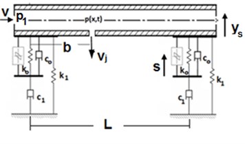
In this work the analysis is based on three methods for supporting the pipe. In first method, the pipe is fixed by a rigid support at each end (pinned-pinned). The second fixation is assumed to be a conventional flexible support at each end (spring and damper), while in the third fixation, the pipe is assumed to be supported at each end by a Magneto-rheological damper (MR damper).
Figs. 1-3 show the layout of pipe and its supports.
Fig. 1Pipe supported by a rigid support
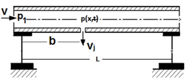
Fig. 2Pipe supported by a flexible support
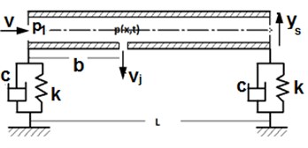
Fig. 3Pipe supported by an MR support
The partial differential equation governing the small lateral vibrations of the pipe is represented by the following equation (Paıdoussis and Issid [23]):
where, is the Dirac delta function, , , is the transverse pipe displacement, distance along the pipe and time, is the modulus of elasticity of pipe material, is the area moment of inertia of the pipe, is the mass per unit length of the pipe, is the mass per unit length of fluid inside the pipe, is the velocity of fluid, is the length of the pipe, is the inner cross section of the pipe and is the fluid pressure at any point along the pipe.
The assumption of unsteady flow imposes the condition that the pressure and flow velocity vary along the pipe. Eq. (1) represents the lateral inertial forces which act on the pipe. The first term is a force component acting on the pipe as a result of up curvature. The second term is a force component acting on the pipe as a result of inertia of the pipe and flow through it. The third term is the force required to rotate the fluid element at each point along the span as a result of Coriolis Effect. The fourth term is a force component acting on the pipe as a result of bending of the pipe.
The force represents the impulse reaction force acting normal to the pipe axis which is resulting from leakage of fluid at a certain point along the pipe (). The impulsive reaction force is represented by:
where, is the fluid jet velocity normal to the pipe axis and relative to the pipe which is bending away from the fluid flow at velocity at point of rupture (), is the area of section parallel to the pipe axis’s through which the fluid jet flows at rupture point, is the density of the fluid.
In many cases of practical importance, the velocity of the fluid jet substantially exceeds the velocity of pipe response so the approximation can be applied, and the reaction impulse force acting on pipe can be represented by:
2.1. Oscillating flow through the pipe
The flow of a fluid through the pipe is assumed to be under influence of periodic pressure gradient. This type of flow occurs for example as oscillating flow under influence of a reciprocating piston, and its theory was given by Shu et al. [24].
It is assumed here that, the pressure gradient caused by the motion of the piston is harmonic and is given by:
Integrating Eq. (4) with respect to , the pressure along pipe length takes the form:
where, is the pressure at pipe inlet, is a constant and is the fluid pulsating frequency.
Moreover, the velocity of pulsating fluid is assumed to be harmonically fluctuating and has the following form:
where, is the mean flow velocity, is the amplitude of the harmonic fluctuation (assumed small).
The velocity of fluid depends on the time while the pressure depends on the distance along the pipe and time .
To find the jet velocity of the fluid at location of leakage, Bernoulli Equation is to be applied between a point inside pipe and point on jet flow outside the pipe for unsteady flow and the following equation can be obtained:
where, is length of fluid jet flow.
By solving Eq. (7), the relation between jet flow velocity and pressure can be obtained.
2.2. MR damper model
The MR damper used for supporting the pipe is chosen according to a Spencer model [25]. The rheological structure of this model is shown in Fig. 3.
Damping force in Spencer’s model can be expressed as:
In which is the displacement of damper, is the internal displacement of damper, is the evolutionary variable that portray the hysteretic behavior of the damper, is the accumulator stiffness, and, are the viscous damping and stiffness at large velocities, is the viscous damping for force roll-off at low velocities and is the initial displacement of the spring.
, , , , are the shape parameters of the hysteresis loops. Spencer [26]showed that the upper bound of the evolutionary variablecan be represented by an ultimate hysteretic strength and its value is represented by:
The parameters , , are assumed to be function of the applied voltage to the damper :
where, is the time constant, is the command voltage.
Table 1 shows the values of the different parameters of Spencer model.
Table 1Parameters for the Spencer model [25]
Parameter | Value | Units |
785 | N.s/m | |
1803 | N.s/Vm | |
3610 | N/m | |
14649 | N.s/m | |
34622 | N.s/Vm | |
840 | N/m | |
0.008 | m | |
12441 | N/m | |
38430 | N/Vm | |
136320 | m-2 | |
2059020 | m-2 | |
58 | ||
2 | ||
190 | s-1 |
The force generated by the MR damper depends on the voltage supplied to the current driver inside the damper. The value of is small relative to and the damper force is formulated as:
Eq. (16) can be put in the form:
where:
2.3. Conventional support
Since the pipe may be fixed at each end by using a conventional flexible support (spring and damper), the reaction force at each end is represented by the following formula:
where, and are the equivalent damping coefficient and spring stiffness respectively.
In order to compare the damping performance of the MR damper with that of a conventional viscous damper, an equivalent damping coefficient must be determined.
The equivalent damping coefficient is obtained by equating the energy dissipated in a full cycle for conventional and MR dampers.
3. Non dimensional equations
Introducing the following dimensionless quantities:
where, is the fundamental frequency of the pipe in the absence of fluid flow and is the atmospheric pressure:
Then Eq. (1) can be written in non-dimensional form as:
where:
Eqs. (3), (5-7) and (17) can be written in non-dimensional form as:
To simplify the equation of motion, the following relations are introduced:
Substituting from Eqs. (36) and (37) into Eq. (24), the following equation is obtained:
Also from Eqs. (36) and (37), the following relation is obtained:
3.1. Numerical solution scheme
The numerical solution of the problem is to be carried out using the finite difference technique. Eqs. (36), (38) and (39) are to be converted into difference form with dimensionless step size and dimensionless time interval in and respectively. The dimensionless difference equations may be written as:
where, and are grid point description for and :
The pulsating velocity of fluid along the pipe before the appearance of the leakage is and then is changed to be after leakage effect.
3.2. Boundary conditions
At both ends of the pipe different boundary conditions are applied depending on the type of support. The following boundary conditions are applied according to the type of support as shown in Figs. 1-3.
For rigid support with (pinned-pinned) ends the non-dimensional displacement and lateral velocity at left and right support are equal to zero and the following relations are to be applied:
For conventional elastic support the shear force equal to the reaction force of the support and the following relation is applied at pipe ends:
where:
where, 1 and –1 for left and right supports respectively.
The finite difference method is used to find the non-dimensional displacement of pipe at left and right ends (). As the support is changed to MR damper type the following relations are applied at pipe ends:
where:
3.3. Numerical example
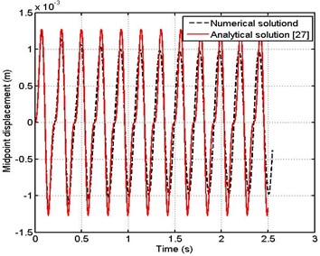
In order to check the accuracy of the numerical technique employed for the solution of the problem considered in the present study, it is validated with analytical solution introduced by M. S. Kozien [27]. The validation is made by assuming no flow inside pipe and a harmonic force is acting in the middle of the pipe with amplitude of 10 N and two frequencies is taken into consideration . The inner and outer diameters of pipe is 45 mm and 50 mm, length of pipe is 3 m, density of pipe is 2800 kg/m 3 and modulus of elasticity is 72 GPa. Figs. 4 and 5 show the displacement of a midpoint of the pipe just after the beginning of vibrations. Two methods of solution are compared, since the first one by using numerical technique used in the present work and the second method by using the analytical solution. From these figures the solution is the same but with small difference as a numerical technique or analytical solution is used.
Fig. 4Midpoint displacement of pipe ω=0.25ωo
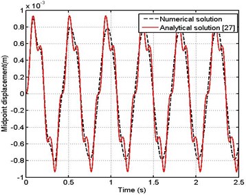
Fig. 5Midpoint displacement of pipe ω=0.5ωo
4. Dynamic response of pipe
In this section, the analysis of the dynamic response of a pipe conveying harmonically pulsating fluid is introduced. The pipe is supported at each end by the three methods mentioned earlier. The first one when the pipe is fixed by a rigid support (pinned – pinned) and the second one the support is changed to be, (conventional flexible support) while the third support is assumed to be (MR damper).
The dimensionless step size is taken equal to 0.02, the dimensionless pulsating frequency is considered to change from 1 to 4. The dimensionless time intervals is taken to be 0.2 and the hole diameter from which leakage is taking place to pipe inside diameter ratio is taken equal to 0.11. Table 2 shows the main parameters used in the mathematical model.
Table 2Main parameters used for the mathematical model
Parameter | Value | Units |
Length of pipe | 3 | m |
Outer diameter of pipe | 50 | mm |
Inner diameter of pipe | 45 | mm |
Modules of elasticity for pipe material | 72 | GPa |
Density of pipe material | 2800 | kg/m3 |
Density of fluid | 1000 | kg/m3 |
Leakage hole diameter | 5 | mm |
Pulsating flow frequency | 1000-4000 | cpm |
Since the flow of the fluid through the pipe is assumed to be under influence of periodic pressure difference, the amount of pulsating pressure along the pipe obviously depends on the distance along the pipe and time. Fig. 6 shows the pressure waves at different locations along the pipe ( 0, 0. 25, 0.5, 0.75, 1).
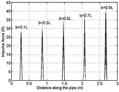
The pipe is subjected to a pulsating force resulting from the leakage at a certain point in the pipe. This force depends on the position of fluid leakage and the velocity and area of jet flow issuing from the pipe at point of leakage.
The history of impulse force acting on the pipe for different locations of leakage is illustrated in Fig. 7. In this figure five positions of leakage are taken into consideration ( 0.1, 0.3, 0.5, 0.7 and 0.9).
Fig. 6Pressure variation for different locations along the pipe
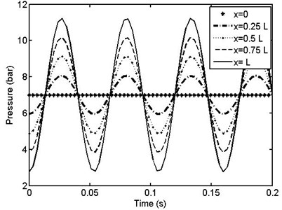
Fig. 7Impulse force acting on the pipe for different locations of leakage
Figs. 8-10 illustrate the time history of pipe supported by different supports as mentioned before when the dimensionless frequency of pulsating fluid and location of leakage along the pipe are taken 2 and 0.1 respectively.
Comparing the maximum value of vertical amplitude of vibrations for the three conditions, it is seen that, the maximum displacement when MR support is used is less than rigid and conventional supports. This means that using an MR damper as a support for the pipe, practically reduces the vibrations of pipes subjected to fluid leakage from any location in the pipe.
Fig. 8Time history of pipe – rigid support b= 0.1L
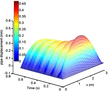
Fig. 9Time history of pipe – flexible support b= 0.1L
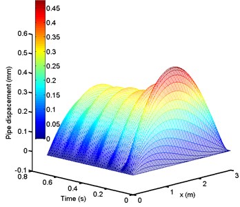
Fig. 11 illustrates a time history of pipe’s midpoint using three types of support. In this case the position of leakage along the pipe is for 0.5 and dimensionless frequency of 2.
From that figure, it is evident that the difference between the three types of support is clear since, the vertical displacement of vibrating pipe decreases as MR damper is used for supporting the pipe.
Fig. 10Time history of pipe – MR support b= 0.1L
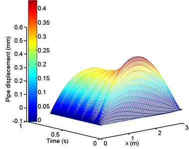
Fig. 12 shows the effect of leakage position on the displacement response of the middle point versus the time when the pipe is supported by the MR damper. The voltage input to the damper is 2 V and dimensionless fluid frequency is 2.
In this figure four different positions of leakage along the pipe are taken into account ( 0.1, 0.5, 0.7 and 1).
It can be seen from this figure that the pipe attains steady state displacement at the same time irrespective the position of leakage. The pipe gives the steady state response at time ( 0.48 s) but with different amplitude depending on the position of leakage.
Fig. 11Mid-point history of pipe for different types of support b= 0.5L
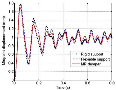
Fig. 12Time history of mid-point of the pipe for different locations of leakage – MR support u= 2 V
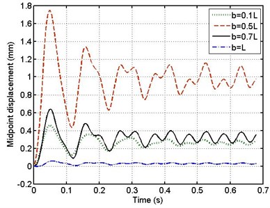
However, the displacement of pipe mid-point increases with the position of leakage changing from (0.1 to 0.5) then decreases as the position of leakage changes from (0.9 to 1) .This means that, when the leakage location is close to the middle point of the pipe the amplitude of vibrations becomes larger.
It is clear from this figure that, as the leakage takes place to the right hand side end of the pipe, vibrations amplitude becomes very small and approximately diminishes.
Fig. 13 shows the relationship between the maximum displacements of pipe using different supports when the location of leakage is changed from 0.1 to 0.9. It can be seen clearly from the figure what has been inferred from Fig. 10 that when the location of leakage takes place close to pipe mid-span it increases the maximum displacement of pipe vibrations. This is besides the MR type of support providing the least maximum value.
Fig. 14 demonstrates the influence of pulsating fluid frequency on nonlinear behavior of a mid-point of the pipe. The pipe is supported by MR damper and three values of frequencies are taken into consideration ( 1124, 1686 and 2249 cpm). Comparing the results, it is seen that, as the pulsating frequency increases the amplitude of vibrating pipe decreases for both the unsteady and steady state responses.
Fig. 13Maximum displacement of the pipe for different types of support
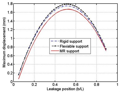
Fig. 14Time history of the mid-point of the pipe for different pulsating frequency – MR support b= 0.5L
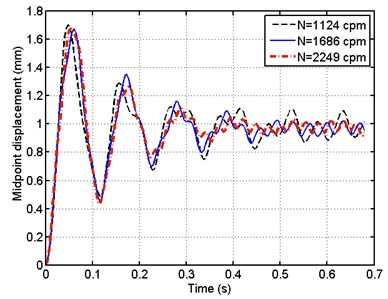
Fig. 15Mid- point history of pipe for different voltage of MR support b= 0.5 L
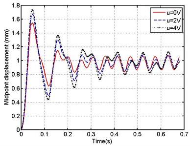
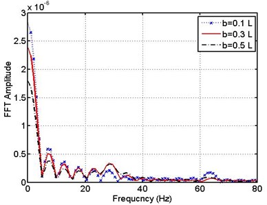
Fig. 16Spectrum (FFT) response of pipe –flexible support for different leakage positions (b/L= 0.1, 0.3, 0.5)
The Magneto-rheological damper is controlled by changing the yield shear stress of the Magnetorheological fluid with voltage, so the performance of MR damper depends on the voltage input to the coil inside the damper.
Fig. 15 shows the influence of voltage input to the damper on the time history of a middle point of the pipe when the position of leakage is assumed to be (0.5). Three values of voltage are considered (0, 2 and 4 V).
It can be seen from this figure that, as the voltage supplied to the damper increases the steady state amplitude of vibrations decreases.
A common way to detect the location of leakage along the pipe is to obtain numerically the spectrum response at point of support of the pipe and the shape of this response gives an indication about the rupture location along the pipe.
Fast Fourier Transform is applied to find the relation between the frequency and vibrations amplitude of flexible support at each end of the pipe.
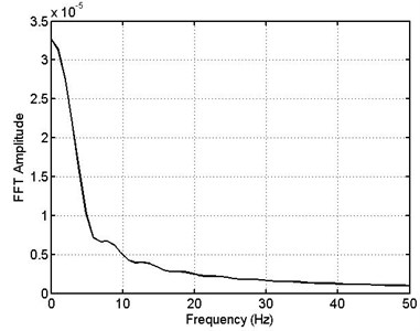
Fig. 16 shows a spectrum of FFT response of a pipe support as the leakage appears in three different locations along the left half of the pipe (0.1, 0.3 and 0.5) . In this case the pipe is supported by a conventional flexible support (spring and damper) and the dimensionless frequency of pulsating fluid is 2. From this figure a transient profile is seen which allows the observer to notice the occurrence of leakage and its position along the pipe. By noting the results of this figure it clear that, when the leak occurs, FFT amplitude of the signals at support changes directly from a maximum value attained with the frequency equal to zero to oscillations their values depend on the position of leakage.
Examining the results of this figure it is found that, as the leakage position changes from 0.1 to 0.5, FFT amplitude at zero frequency decreases from 2.8×10⁻⁶ to 1.75×10⁻⁶. So that according to the spectrum response graph it is very easy to detect the leak and its position.
Fig. 17 shows a spectrum FFT response for the conventional support of the pipe with the leakage appearing at three different locations in the right half of the pipe ( 0.7, 0.9 and 1) . This with the dimensionless frequency of pulsating fluid of 2. From the results of this figure it is found that, as the leakage position changes from 0.7 to , FFT amplitude at zero frequency decreases from 1.18×10⁻⁶ to 0.05×10⁻⁶.
Comparing the results of Fig. 16 and Fig. 17, it is found that, when the leakage appears at the right half of the pipe, FFT amplitude at zero frequency is less than that for the case of leakage appearing at the left half of the pipe.
Also when the leakage appears at the end of pipe, FFT amplitude is 0.05×10⁻⁶ at zero frequency and then diminishes irrespective of the value of frequency.
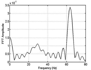
Fig. 18 shows FFT response for conventional support of normal pipe (no leakage). It is found from this figure that, FFT response of pipe for no leakage is very small as compared with the case of existing leakage along the pipe.
Fig. 17Spectrum (FFT) response of pipe –flexible support for different leakage positions (b/L= 0.7, 0.9, 15)
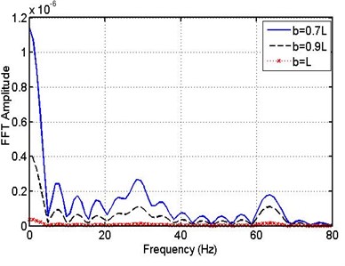
Fig. 18Spectrum (FFT) response of pipe – flexible support for no leakage
To detect the leakage along the pipe when the support of pipe is MR damper, the signal created at this support is converted to FFT spectrum.
Fig. 19 shows a spectrum FFT response of MR support as the leakage appears at three different locations at the left half of the pipe ( 0.1, 0.3 0.5) with dimensionless frequency of pulsating fluid of 2.
From this figure a transient profile is seen which allows us to notice the occurrence of leakage and its position along the pipe.
This figure also shows the same behavior as that pointed out for the flexible support case where the values of peaks of oscillations depend on the position of leakage. It is found also that, when the frequency is larger than 20 Hz. the peaks diminish irrespective to the position of leakage.
Examination of the results of this graph it is found that, as the leakage position changes from 0.1 to 0.5 the FFT amplitude decreases from 8.8×10⁻⁵ to 6.8×10⁻⁵. So that according to the spectrum response graph it is also very easy to detect the leak and its position as for the case of flexible support mentioned earlier.
Fig. 20 shows also the relation between frequency and FFT amplitude while the leakage appears in right half of the pipe ( 0.7, 0.9 and ).
Comparing the results of Fig. 19 and Fig. 20, it is found that, when the leakage appears in the right half of the pipe, FFT amplitude at zero frequency is less than that for the case appearing at the left half of the pipe. Also when the leakage appears at the right end of pipe, FFT amplitude has a smallest value at zero frequency.
Fig. 19Spectrum (FFT) response of pipe – MR support for different leakage positions x= (0.1, 0.3, 0.5) L
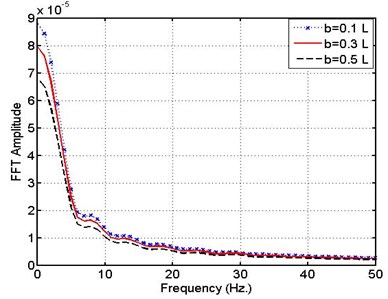
Fig. 20(FFT) response of pipe – MR support for different leakage positions b= (0.7, 0.9, 1) L
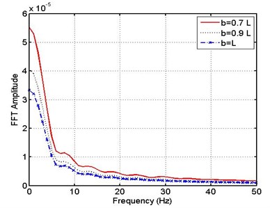
Fig. 21 shows FFT response for MR support of normal pipe (no leakage). It is found from this figure that, FFT response of pipe for no leakage is very small as compared with the case of existing leakage along the pipe.
Fig. 21(FFT) response of pipe – MR support for no leakage
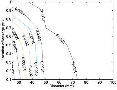
In industrial applications the diameter of pipes conveying fluid is a main factor affecting the vibrations of pipe subjected to leakage at a certain point. So detection of the leakage and its position for different diameters of pipe is important to be examined. Fig. 22 shows the relation between pipe diameter and maximum FFT amplitude which is indicated at zero frequency for different positions of leakage. In this case the pipe is supported by a flexible support. According to this figure and graph of FFT spectrum it is easy to detect the position of leakage numerically for different sizes of pipe.
Fig. 23 shows the same concept but when the pipe is supported by an MR damper.
Fig. 22Maximum FFT amplitude – leakage position for different pipe diameters – flexible support
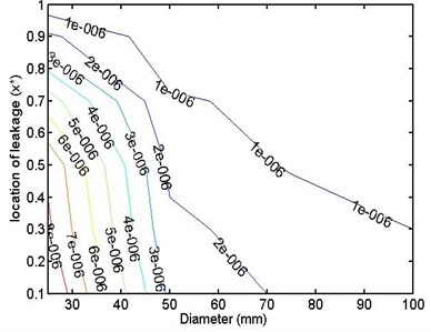
Fig. 23Maximum FFT amplitude – leakage position for different pipe diameters – MR support
5. Conclusions
1) For a pipe conveying pulsating flow the maximum pulsating force appears beside the right hand side support of the pipe, in presence of leakage.
2) Increasing the voltage input to MR support decreases the amplitude of vibrations acting on the pipe.
3) As the leakage location changes from left support to the midpoint of the pipe the vibrating response increases and then decreases as the leakage location changes from the midpoint to the right support.
4) Using MR Damper as support for pipe conveying pulsating flow is suitable to decrease the vibrations resulting from leakage at a certain point in the pipeline
5) When the pipe is supported by a conventional flexible support, a graph of FFT spectrum for response of a point supporting the pipe gives an indication for the leakage and its position since, as the frequency changes from zero to 80 Hz the spectrum fluctuates with different amplitudes its value depends on the position of leakage along the pipe.
6) When the pipe is supported by MR support, a graph of FFT spectrum for response similar to that of conventional flexible support case gives the same indication of leakage and its position in the frequency range from zero to 50 Hz.
7) As the value of pulsating frequency increases the amplitude of vibrations attained by pipe decreases.
8) A flow chart is constructed to show the FFT amplitude for different diameters of pipe when it is supported by conventional or MR support. This chart can be used to detect the leakage position for different pipe diameters.
References
-
Chen S. S. Dynamic stability of tube conveying fluid. Journal of Engineering Mechanical Division, Vol. 97, 1971, p. 1469-1485.
-
Paidoussis M. P. Fluid-Structure Interactions, Slender Structures and Axial Flow. Vol.1, Academic Press, Amsterdam, The Netherlands, 1998, p. 572.
-
Paidoussis M. P. Fluid-Structure Interactions: Slender Structures and Axial Flow. Academic Press, Amsterdam, The Netherlands, Vol. 2, 2003, p. 1573-1585.
-
Nikolic M., Rajkovi M. Bifurcations in nonlinear models of fluid-conveying pipes supported at both ends. Journal of Fluids and Structures, Vol. 22, Issue 2, 2006, p. 173-195.
-
Folley C. N., Bajaj A. K. Spatial nonlinear dynamics near principal parametric resonance for a fluid-conveying cantilever pipe. Journal of Fluids and Structures, Vol. 21, Issues 5-7, 2005, p. 459-484.
-
Jensen J. S. Fluid transport due to nonlinear fluid-structure interaction. Journal of Fluids and Structures, Vol. 11, Issue 3, 1997, p. 327-344.
-
Jeong W. B., Seo Y. S., Jeong S. H., Lee S. H., Yoo W. S. Stability analysis of a pipe conveying periodically pulsating fluid using finite element method. Mechanical Systems Machine Elements and Manufacturing, Vol. 49, Issue 4, 2007, p. 1116-1122.
-
Shen H. J., Wen J. H., Yu D. L., Wen X. S. Flexural vibration property of periodic pipe system conveying fluid based on Timoshenko beam equation. Acta Physica Sinica, Vol. 58, Issue 12, 2009, p. 8357-8363.
-
Lee P. J., Lambert M. F., Simpson A. R., Misiunas D. Leak location in single pipelines using transient reflections. Australian Journal of Water Resources, Vol. 11, Issue 1, 2007, p. 53-66.
-
Shayo L. K., Ellen C. H. The stability of finite length circular cross-section pipes conveying inviscid fluid. Journal of Sound and Vibration, Vol. 37, Issue 4, 1974, p. 535-545.
-
Łuczko Jan, Czerwiński Andrzej Parametric vibrations of pipes induced by pulsating flow in hydraulic systems. Journal of Theoretical and Applied Mechanics, Vol. 52, Issue 3, 2014, p. 719-730.
-
Chen S. S. Vibrations of Continuous Pipes Conveying Fluid. Flow Induced Structure Vibrations, Berlin, Springer-Verlag, 1974, p. 663-675.
-
Miller H. L. Control valves – a source of pipe vibration. ASME Piping and Pressure Vessel Conference, Pittsburg, PA, 1988.
-
Hunaidi O., Wang A., Bracken M., Gambino T., Fricke C. Acoustic methods for locating leaks in municipal water pipe networks. International Conference on Water Demand Management, Dead Sea, Jordan, 2004.
-
Rousselet J., Herrmann G. Dynamic behavior of continuous cantilevered pipes conveying fluid near critical velocities. Journal of Applied Mechanics, Vol. 48, 1981, p. 943-947.
-
Mostafapour A., Davoudi S. Analysis of leakage in high pressure pipe using acoustic emission method. Applied Acoustics, Vol. 74, Issue 3, 2013, p. 335-342.
-
Blevins R. D. Flow – Induced Vibrations. Van Nostrand Reinhold Co., 1977, p. 287-312.
-
Pedro J. Lee, Vitkovsky P John. Leak location using the pattern of the frequency response diagram in pipelines – a numerical study. Journal of Sound and Vibrations, Vol. 284, Issues 3-5, 2005, p. 1051-1073.
-
Mpesha W., Hanif M., Hauhry C., Irwin B. Leak detection in pipes by frequency response method using a step excitation. Journal of Hydraulic Research, Vol. 40, Issue 1, 2002, p. 55-62.
-
Pedro J. L., John P. V., Martin F. L. Frequency domain analysis for detecting pipeline leaks. Journal of Hydraulic Engineering, 2005, p. 596-604.
-
Koppel T., Ainola L., Puust R. A mathematical model for the determination of leakage in mains and water distribution networks. Proceedings of the Estonian Academy of Sciences, Engineering, Vol. 13, Issue 1, 2007, p. 3-16.
-
Pedro Lee J., John Vítkovský P., Martin Lambert F., Angus Simpson R., James Liggett Leak location in pipelines using the impulse response function. Journal of Hydraulic Research, Vol. 45, Issue 5, 2007, p. 643-652.
-
Paidoussis M. P., Issid N. T. Dynamic stability of pipes conveying fluid. Journal of Sound and Vibration, Vol. 33, Issue 3, 1974, p. 267-294.
-
Shu J.-J., Burrows C. R., Edge K. A. Pressure pulsations in reciprocating pump piping. Proceedings of the Institution of Mechanical Engineers, Vol. 211, 1997, p. 229-237.
-
Liao W. H., Lai C. Y. Harmonic analysis of a magnetorheological damper for vibration control. Smart Mater and Structure, Vol. 11, 2002, p. 288-296.
-
Spencer B. F. Jr Reliability of Randomly Excited Hysteretic Structures. Lecture Notes in Engineering, Springer-Verlag, Berlin, 1986.
-
Kozien M. S. Analytical solutions of excited vibrations of a beam with application of distribution. ACTA Physica Polonica, Acoustic and Biomedical Engineering, Vol. 123, Issue 6, 2013, p. 1029-1033.
Cited by
About this article

