Abstract
This paper presents an approach to modeling the slippage of a robot’s rubber tracks moving on a non-deformable surface. A single horizontal deflection of a one-track lug is considered. The issue is modeled by FEM and verified by track lug deflection measurement and trajectory motion analysis. As a measurement device, a vision system is developed and configured. The vision-based measurement method can be considered as a new approach for estimating a robot’s track slippage.
1. Introduction
When a crawler track vehicle moves, there are losses, regardless of whether it is traveling in a straight line, uphill, or in a curve. This is due to the crawler slipping, and to the deflection of its lugs or the ground. These factors should be taken into account when designing a crawler track robot, developing its mathematical model, and modeling its kinematics, dynamics or steering [1], [2]. There are many articles that deal with crawler drives in robot development, and with their advantages, but little is said about their performance when it comes to slipping, and this aspect is important for this type of drive when dynamics are considered, for example: dynamic wheel-track-terrain interactions [3], flexible mono-tread mobile tracks [4], research into trajectory tracking of crawler robots [2], a theoretical and experimental investigation of rubber tracks [5], soil-track interaction [6], a dynamic three-dimensional model of a track tractor [7], a detailed single-link track model [8], an experimental study of a lightweight tracked vehicle [9], a spatial motion analysis model of tracked vehicles [10], distribution of vibration from road roughness [11] with advanced signal processing devices [12], the motion of transportation machine with packages on uneven road, numerical and experimental investigation of the transportation device [13] and steering systems are prototyped. The authors of [14] discuss the results of studies related to the application of new solutions for crawler track robot suspension, which involve a torsion spring element. The simulation results are compared and analyzed to improve traction parameters. The author of [15] presents a numerical method for the dynamic analysis of high mobility military crawler track vehicles. It considers obstacles as dynamic impulses of contact forces. In the motion equations, it takes into account the weight of each track link, its elastic elongation, and flexible elastic effects on its upper and lower surfaces. The authors of [16] discuss the steering of a fully active suspension that improves the ride comfort, which makes it possible to increase the speed in a rough terrain. Noteworthy is the hydraulic actuator force controller that tracks commands generated by higher-level controllers, and levels roughness, thus increasing comfort. The authors of [17] present a system for crawler track tension monitoring in a flat terrain. A crawler track vehicle’s mobility is mainly dependent on the characteristics of its guides’ assembly, and on the crawler-ground interactions [1, 5]. Crawler track tension is closely related to the vehicle’s maneuverability and the durability of its suspension components. In order to minimize excessive loads and adhesion loss, it is necessary to maintain the optimum crawler track tension during maneuvering. Applied in the study is an intermediate monitoring system of the track tension in a flat terrain. The authors of [18] present a series of climbing robots with different types of clamping mechanisms based on crawler drives. These robots are designed for industries related to inaccessible and dangerous environments, such as tall buildings. As the ground contact, they utilize the following adhesion mechanisms: suction cups, magnets, and adhesives, in order to improve adhesion.
In this paper, a way of modeling the slippage of a rubber crawler track is presented. The robot, while driving on hard surfaces (concrete, asphalt), has deformed lugs, causing losses. Experimental verification based on vision-based measurement is investigated. The results obtained from numerical and experimental validation are presented and discussed. To the best of the author’s knowledge, no reports or validation exist of track lug deformation computing using vision-based measurement. The new approach to track lug deformation measurement based on the developed vision system, presented in the paper, enables the slippage of a crawler robot to be estimated.
2. Robot with crawler drive
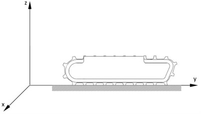
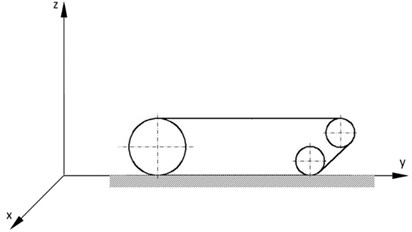
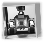
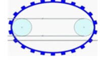
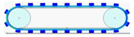
Crawler track drive systems are subject to different types of impacts which are variable over time. The description of the crawler track motion in real rough terrain conditions with variable parameters is very complicated. Crawler tracks Fig. 1(a) in very simplistic terms can be modeled as an inextensible strip with a shape defined by the drive wheel, straining pulleys, and non-deformable substrate Fig. 1(b) [19-22].
Fig. 1Track model: a) CAD Model, b) Simplified model
a)
b)
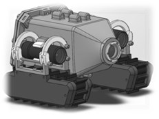
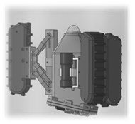
The developed robot platform [21-23] is based on two track modules with integrated motors Fig. 2. Pipeline inspection is a popular application field of mobile robots. Since access to a particular segment of a pipeline is usually limited; various in-pipe inspection mobile robots are utilized.
Fig. 2CAD model
The robot is intended to operate in circular and rectangular pipes and ducts oriented horizontally and vertically. Key feature of the tracks are:
• height: 60 mm, width: 50 mm, length: 170 mm, weight: 1,4 kg (aluminium);
• speed: 0 to 9 m/min;
• pull rating: 6,5 kg per track, depth rating: 0-30 m.
The slippage of the track is calculated using the following formula [20, 23, 24]:
where: – is the number of track lugs in contact with the ground, – single horizontal deflection of the track lug or ground Fig. 3, – length of the track load bearing segment.
When a crawler track is equipped with lugs, then when traveling in a muddy terrain the lugs sink into the ground, leaving it deformed Fig. 3.
Fig. 3Scheme of track lug plunging
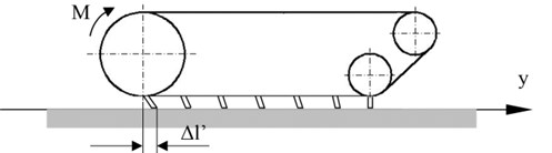
It can be seen that a lug sinking into the ground causes its substantial deflection. The ground’s tangential reaction depends on:
• inclination angle of the track's front section;
• type of the ground;
• lug dimensions.
When a crawler tracked vehicle is traveling on a substrate with a low rolling resistance and high cohesion, then the tangential reaction in its lug is approximately equal to the rolling resistance. Under such conditions, the crawler slips are absent or very small. When traveling on a substrate with a high rolling coefficient and low cohesion, the substrate's tangential reaction is also carried by other lugs sunk in the substrate, and there are single horizontal deflections of the substrate. When a tracked vehicle with rubber lugs is traveling on a hard surface (e.g. a concrete paved road), then the lugs are subject to horizontal deflection. The modeling, measurement and consideration of these factors is difficult.
3. Modeling using FEM
In this paper, analysis of the movement of a caterpillar was performed using ABAQUS software. The product is popular with academic and research institutions due to its wide material modeling capability, and the program’s ability to be customized. To shorten the time of calculation, a number of simplifications that does not have a greater influence on the correctness of the results was used. Only two driving wheels and idlers were modeled. Lugs were modeled with a belt connecting them with a deformable body made of rubber. The movement of the actual caterpillar is possible with initial belt tension on the drive wheels. The simulation was divided into two stages. The first comprising stretching and belt tension Fig. 4, and the second including movement of the track on an established distance. Correct performance of belt tension required the adoption of a round belt shape which, after the initial tension, took the shape of the actual model.
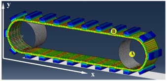
The second phase of stimulation requires the adoption of the necessary parameters. On the basis of data in the literature, the coefficient of friction between the lugs and the track was assumed. The maximal speed of the drive wheel crawler was taken from technical specifications. It was assumed that there was a lack of slippage between the drive wheel and crawler belt. The test distance on which the movement took place was 0.7 m. The acceleration phase, constant velocity motion and deceleration were assumed. The characteristic points A (crawler track body) and B (crawler track lug) shown in Fig. 5 were used for analysis of the crawler’s movement.
Fig. 4Stages of Crawler belt tension, a) primary, b) intermediate, c) the final shape crawler belt
a)
b)
c)
Fig. 5Crawler with characteristic points
The simulation was conducted using a General Static module. For each node model, it is possible to read the coordinates at any instant of time. All parameters can be read out in the form of a table and graph, as well as exported to external programs to enhance their visibility. This allows a direct comparison of numerical calculations, both analytical and experimental. The obtained simulation data are shown in the graphs Fig. 6.
Fig. 6a) The displacement of point A, b) The velocity of point A
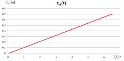
a)
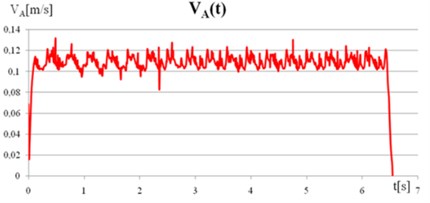
b)
The axes in the graphs were adopted along the motion trajectory. Fig. 6(a) shows that the movement on the established distance of 0.7 m took approx. 6.5 sec. In the graph of speed Fig. 6(b) the acceleration and deceleration phases of the crawler can be seen. The speed variation may be due to slippage between the track lugs and the ground, and also discretization errors of the model. The analysis of the displacement and velocity is also performed for point B located on the crawler track’s lug.
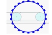
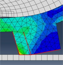
In Fig. 7 the point displacements in the crawler lug shown have waveforms due to their curved trajectory Fig. 8. The coordinate increases until the lug contact with the track, then its value is constant and increases again with crawler movement. The characteristics shown in Fig. 8 are similar to the ideal characteristics of the crawler slippage derived from the literature [25, 26]. Tools available in the ABAQUS 6.11 software allow the evaluation of the so-called single horizontal deflection of the track lug Fig. 9. With the assumed model parameters, the factor concerned the lug and amounted to = 0.0013 m.
Fig. 7a) The displacement of point B along the x axis, b) The displacement of point B along the y-axis
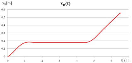
a)
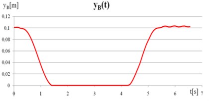
b)
Fig. 8The trajectory of point B and single deflection of the track lug
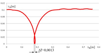
Fig. 9Lug deformation in contact with a stiff track
The crawler movement analysis in FEM software presented in the paper is useful for describing the kinetics of an inspection robot. This enables the mathematical model verification and the choice of the coefficients appearing in the equations of motion. FEM simulations make it possible to analyze the phenomenon of robot slippage, as well as ground and track lug deflection, essential for the movement of crawler vehicles.
4. Experimental setup
In order to determine the parameters needed to describe the robot kinematics and dynamics, laboratory tests of the robot's crawler track motion were conducted. Displacement, the maximum speed, acceleration, trajectory motion and deflection of the crawler track lugs were investigated. The experiment was performed in the laboratory using a test platform with fixed crawler tracks, moving on a horizontal vibration-insulated table.
The developed vision system consisted of a Phantom v9.1 high-speed camera equipped with a Carl Zeiss 18 mm lens, a lighting system and TEMA Automotive motion analysis software. Tema is dedicated software for motion analysis in the automotive industry.
The software is equipped with tools to automatically track markers and advanced post-processing tools. The experimental rig is depicted in Fig. 10.
Fig. 10The experimental rig
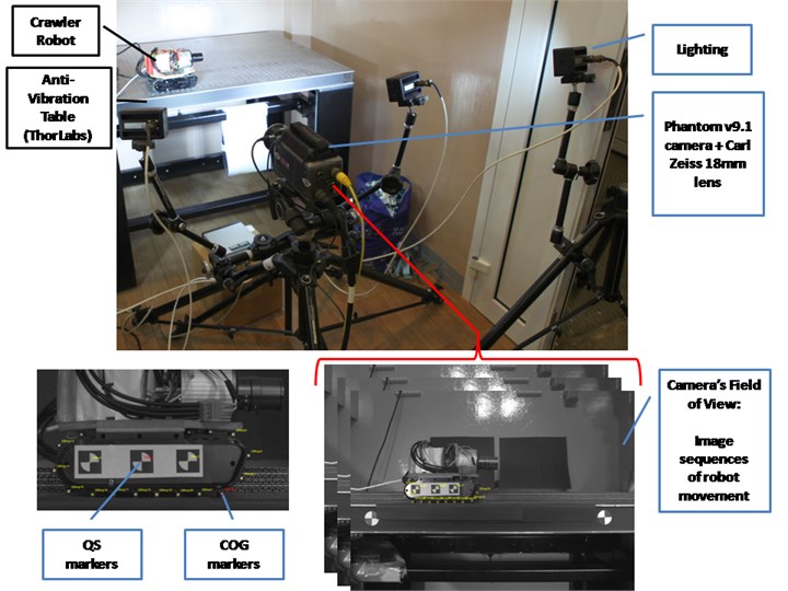
The main components of the laboratory rig and its settings:
a) Developed crawler robot with markers to be tracked;
b) Anti-vibration table (Thorlabs table);
c) Phantom v9.1 camera (image resolution 1632×1200 pixels, frame rate 100 frame/sec) equipped with a Carl Zeiss 18 mm f/3.5 Distagon T* lens;
d) Lighting: Visual Instrumentation Corporation, four modules No. 900405.
Vision-based measurement was consisted of the following steps:
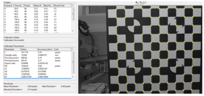
Firstly, the vision system calibration procedure was performed. As a result, internal camera parameters, distortion coefficients and the scale factor were estimated Fig. 11.
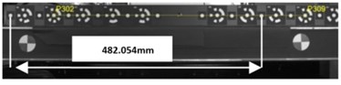
Distortion coefficients were necessary for the removal of optical distortions from the captured images before measurement was carried out. In order to express findings in metric units, a scale coefficient was calculated based on the known distance between two points (P302 P309 482.054 mm) of standard length presented in Fig. 11. The scale factor represented the spatial resolution of the vision system and equaled 0.3905 mm/pixel. Due to the 0.01 sub-pixel capabilities of Tema software, the theoretical measurement accuracy amounted to 0.0039 mm.
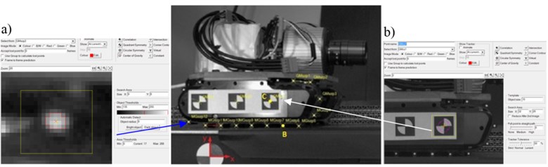
Two types of markers were utilized for tracking the robot’s body and crawler track lugs Fig. 10, Fig. 12. “COG markers” in the form of white circles were stuck to the crawler track lugs and “QS markers” to the robot’s body.
Markers denoted as “COG markers” were analyzed by center of gravity algorithm based on second moment methods whilst “QS markers” by quadrant symmetry algorithm related to edge detector methods. The exemplary Tema tracking settings are presented in Fig. 12.
Fig. 11Vision system calibration results: a) internal camera calibration results, b) length standard used for scale factor calculation
a)
b)
Fig. 12Two types of markers tracked by Tema Automotive software and examples of: a) “Center of gravity” (COG) and b) “Quadrant symmetry” (QS) algorithm settings
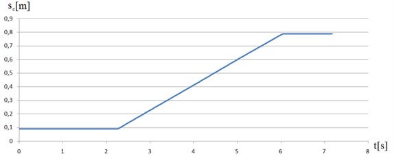
For the purpose of the measurement noise estimation 100 image sequences were acquired in the stationary robot position. Standard deviations were calculated for each type of marker. In the case of COG algorithm the measurement noise amounted to 0.0065 mm whilst for QS method 0.0041 mm. As a result of Tema tracking process displacement and velocity of characteristic robot’s point C and trajectory motion for each crawler track lugs (points B) were investigated Figs. 13-15. Displacement and velocity of the C point are shown in Figs. 13-14.
Fig. 13Displacement of the characteristic point C
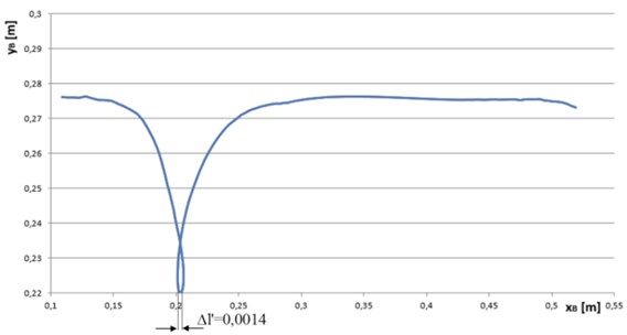
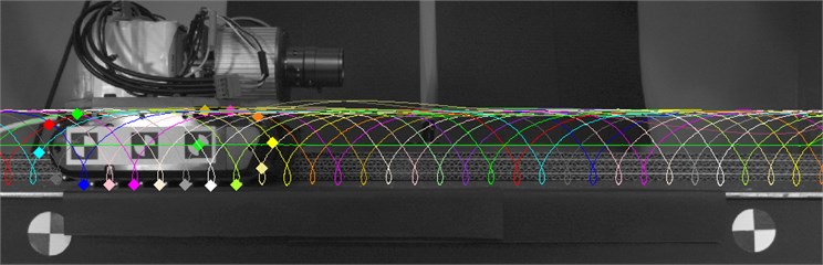
A sample trajectory motion of crawler track lugs measured and computed by the developed vision system is presented in Fig. 16. Based on vision-based measurement results (the deflection of track lugs computation) the slippage of the track Eq. (1) amounted to 0.07716:
where: 0,127 m, 8.
Fig. 14Velocity of the characteristic point C
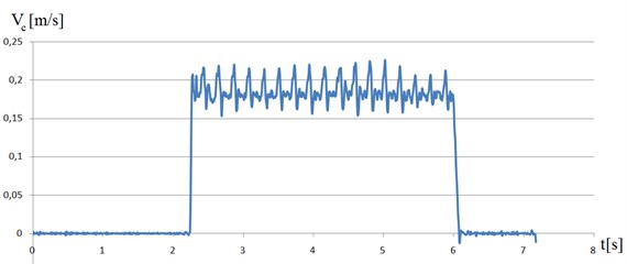
Fig. 15The trajectory motion of the point B and deflection of the single track lug
In the case when 1, it indicates the whole track slippage, if 0 the track is moved without slippage. The motion analysis findings of crawler tracks obtained from FEM and the developed vision system are convergent and confirm the value levels of the track lug slippage and deflection. The possibility of computing crawler track slippage provides users with an opportunity to describe the kinematics and dynamics of crawler robots. In addition, vibrations observed in the numerical simulation shown in Fig. 6(b) as the change in speed during the movement was confirmed by the experiment (Fig. 14). This is due to contact of lugs track with the ground.
Fig. 16Trajectory motion of crawler track lugs calculated by the developed vision system
5. Conclusions
It has been experimentally proven that usage of modern measurement methods allows users to determine single horizontal deformation of a track lug, which has also been presented in the numerical tests performed in FEM software. The “noises” appearing between the ground and the robot tracks are difficult to measure and also difficult to model. The slippage of a single track is modeled by Eq. (1), in which single horizontal deformation of the track’s rubber lug is unknown during the object’s movement on hard ground (asphalt, concrete) or in which the discussed deformation of the track’s steel lug is unknown during the robot’s movement on soft ground (sand, soil). The slippage can be estimated knowing the number of lugs having contact with the ground, the length of the track’s carrying section and measuring the discussed deformation. It’s very significant from the perspective of modeling and controlling the designed caterpillar robot. Verification of the numerical results was performed by the developed non-contact measurement system with the application of a high speed camera. In order to achieve high measurement resolution, the vision system architecture was developed and its configuration was arranged. In the literature, there are no reported uses of a vision system for measuring lug deformation to calculate caterpillar slippage. For this reason, the measurement method presented in the paper can be considered as a new approach for estimating a robot's track slippage.
References
-
Dar T. M., Longoria R. G. Slip estimation for small-scale robotic tracked vehicles. American Control Conference, 2010, p. 6816-6821.
-
Li G., Li X. Research on trajectory tracking of crawler robot based on sliding mode control. The 26th Chinese Conference on Control and Decision, 2014, p. 518-523.
-
Dhir A., Sankar S. Assessment of tracked vehicle suspension system using a validated computer simulation model. Journal of Terramechanics, Vol. 32, Issue 3, 1995, p. 127-149.
-
Kinugasa T., et al. Measurement of flexed posture for flexible mono-tread mobile track: Fundamental test and validation using new flexible displacement sensor. Proceedings of SICE Annual Conference, 2010, p. 867-872.
-
Okello J. A., Watany M., Crolla D. A. A theoretical and experimental investigation of rubber track performance models. Journal of Agricultural Engineering Research, Vol. 69, Issue 1, 1998, p. 15-24.
-
Park W. Y., et al. Prediction of the tractive performance of a flexible tracked vehicle. Journal of Terramechanics, Vol. 45, Issue 1, 2008, p. 13-23.
-
Rabbani M. A., et al. Prediction of the vibration characteristics of half-track tractor considering a three-dimensional dynamic model. Biosystems Engineering, Vol. 110, Issue 2, 2011, p. 178-188.
-
Rubinstein D., Coppock J. L. A detailed single-link track model for multi-body dynamic simulation of crawlers. Journal of Terramechanics, Vol. 44, Issue 5, 2007, p. 355-364.
-
Senatore C., Jayakumar P., Iagnemma K. Experimental study of lightweight tracked vehicle performance on dry granular materials. International Annual Meeting American Society of Agronomy, Crop Science Society of America, Soil Science Society of America, 2013.
-
Yamakawa J., Watanabe K. A spatial motion analysis model of tracked vehicles with torsion bar type suspension. Journal of Terramechanics, Vol. 41, Issue 2, 2004, p. 113-126.
-
Burdzik R. Implementation of multidimensional identification of signal characteristics in the analysis of vibration properties of an automotive vehicle’s floor panel. Eksploatacja i Niezawodność – Maintenance and Reliability, Vol. 16, Issue 3, 2014, p. 439-445.
-
Jamro E., Wielgosz M., Bieniasz Slawomir B., Cioch W. FPGA-ARM heterogeneous system for high speed signal analysis. Solid State Phenomena, Vol. 180, 2012, p. 207-213.
-
Ragulskis K., et al. Numerical and experimental investigation of the axi-symmetric fluid transportation device. Ultragarsas “Ultrasound”, Vol. 46, Issue 1, 2014, p. 16-19.
-
Jurkiewicz A., Nabagło T., Kowal J., Apostoł M. A new suspension system of an autonomous caterpillar platform. Journal of Theoretical and Applied Mechanics, Vol. 52, Issue 4, 2014, p. 857-867.
-
Lee K. A numerical method for dynamic analysis of tracked vehicles of high mobility. KSME International Journal, Vol. 14, Issue 10, 2000, p. 1028-1040.
-
Donahue M. D., Hedrick J. K. Implementation of an Active Suspension, Preview Controller for Improved Ride Comfort, Nonlinear and Hybrid Systems in Automotive Control. Springer, 2003, p. 1-21.
-
Huh K., Cho B. H., Choi J. H. Development of a track tension monitoring system in tracked vehicles on flat ground. Proceedings of the Institution of Mechanical Engineers, Part D: Journal of Automobile Engineering, Vol. 215, Issue 5, 2001, p. 567-578.
-
Lee G., Kim H., Seo K., Kim J., Sitti M., Seo T. Series of multilinked caterpillar track-type climbing robots. Journal of Field Robotics, 2014.
-
Ciszewski M., Buratowski T., Giergiel M., Kurc K., Małka P. Mobile inspection robot. Applied Mechanics and Materials, Vol. 319, 2013, p. 385-392.
-
Ciszewski M., Buratowski T., Giergiel M., Małka P., Kurc K. Virtual prototyping, design and analysis of an in-pipe inspection mobile robot. Journal of Theoretical and Applied Mechanics, Vol. 52, Issue 2, 2014, p. 417-429.
-
Giergiel J., Kurc K., Szybicki D. Identification of the mathematical model of an underwater robot using artificial intelligence. International Journal of Technical University of Lódź, Mechanics and Mechanical Engineering, Vol. 18, Issue 2, 2014, p. 135-149.
-
Szybicki D., Kurc K., Muszyńska M., Sobaszek M. Dynamics of inspection robot with crawler drive. Journal of Civil Engineering, Environment and Architecture, Vol. 31, Issue 2, 2014, p. 149-159.
-
Giergiel J., Kurc K., Szybicki D., Buratowski T., Trojnacki M. Modeling the dynamics of underwater robot. Modelling in Engineering, Vol. 14, Issue 45, 2012, p. 45-51, (in Polish).
-
Giergiel M., Buratowski T., Małka P., Kurc K., Kohut P., Majkut K. The project of tank inspection robot. Key Engineering Materials, Vol. 518, 2012, p. 375-383.
-
Burdziński Z. Teory of Motion of Tracked Vehicle. WKŁ, Warsaw, 1972, (in Polish).
-
Dajniak H. Tractors: Motion and Design Theory. WKŁ, Warsaw, 1985, (in Polish).
About this article
