Abstract
In most cases, the hoisting cable in the cable-guided hoisting system is connected to the hoisting bucket with the swivel. The coupled longitudinal-torsional responses of the hoisting cable with time-varying length are investigated. The hoisting cable and two guiding cables are discretized by employing the assumed modes method, while the equations of motion are derived using Lagrange equations of the first kind, where a coefficient varying from 0 to 1 is introduced to represent the free spinning, proportional and self-locking swivels. The longitudinal and torsional displacements with different swivels are obtained. The results indicate the torsional displacement in the free spinning swivel is much larger than that in the proportional and there is one resonance in the former, while the longitudinal resonance in the free spinning swivel occurs earlier than that in the other two, which implies the system frequencies decrease. In addition, the presented model could also be used to describe the coupled vibration in the rigid rail-guided hoisting system but needs more modes.
1. Introduction
Cables, due to their light weight and their ability to resist relatively large axial loads, have been extensively employed in diverse engineering applications [1-3]. However, they are subjected to large-amplitude vibrations for their high flexibility and low internal damping. Thus, the dynamic behavior of cables has been studied widely for decades. Recently, the coupled vibration of the cable with time-varying length has attracted a great deal of attention and various approaches have been proposed. Wang et al. [4] analyzed the coupled lateral- transverse-longitudinal dynamics of an underwater, drawn cable with an attached mass. A variable-domain element is adopted to discretize the equations of motion. Later, Kaczmarczyk and Ostachowicz [5] exhibited the coupled lateral-longitudinal dynamic response of the catenary-vertical ropes in the deep mine hoisting system and obtained the numerical solution by using the Rayleigh-Ritz method. Zhang et al. [6] presented the coupled lateral-longitudinal vibration model of the vertically translating elevator cables subjected to the general initial conditions and the external excitation with Galerkin method. Ren and Zhu [7] presented the longitudinal and lateral vibrations of a moving two-cable one-rigid-body-car system, in which the rotation of the car is considered.
Cables are characterized by the coupled longitudinal-torsional behavior when subjected to the external loads. Therefore, the vibration analysis of the coupled axial-torsional cable is of great significance. Samras [8] tested experimentally the coupling coefficients and discovered that the axial-torsional stiffness coefficient is approximately equal to the torsional-axial stiffness coefficient. Hashemi and Roach [9] presented the derivation of a dynamic finite element for the coupled extension-torsion vibration analysis of the cable and evaluated the coupled frequencies.
However, few researchers concentrated on the coupled longitudinal -torsional dynamic responses of the hoisting cable with time-varying length, caused by the external displacement excitation. Some problems have arisen in the hoisting cable of cable-guided hoisting system shown in Fig. 1, which is used to sink the deep vertical shaft [10]. This system is mainly composed of one hoisting cable, two guiding cables, a hoisting bucket and a swivel, where the semi rotation resistant cable (18×7) is connected to the bucket with the swivel. The most commonly used swivel is the free spinning swivel. During loading and unloading, the free spinning swivel will always rotate back and forth, causing a series of effects: the tension-torsion stresses caused by the rotation will considerably reduce the wire rope’s fatigue strength, especially in the vicinity of the swivel [11]. However, the self-locking swivel, a more sophisticated version, is designed to prevent the cables from unlaying. On the one hand, the torsion of hoisting cable is easy to destroy the electric cables wound around the surface of the hoisting cable; on the other hand, the torsion of cable aggravates the longitudinal vibration of itself and brings about the slight rotation of the bucket. These two facts reduce the performance of rescue capsules greatly both on safety and comfort. Therefore, it is significant to recognize the essential difference between two kinds of swivels.
This paper is organized as follows. In Section 2, the coupled vibration model is established by adopting Lagrangian multipliers. Particularly, a coefficientvarying from 0 to 1 is introduced to represent the free spinning, proportional and self-locking swivels. In Section 3, the results of the longitudinal and torsional responses from different swivels are analyzed and compared. Finally, Section 4 draws some conclusions.
2. Theoretical investigation
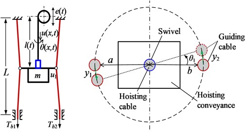
For simplicity, the hoisting system can be modelled as one vertically translating model described by a cylindrical coordinate system. This model is composed of one hoisting cable of length at time instant , two guiding cables of length and one bucket with mass attached to the lower end of the hoisting cable. The bucket is supported by the two guiding cables through two guide sleeves. The upper ends of two guiding cables are fixed to the derrick and the lower ends are constrained laterally and tensioned by the preloads and ; the displacements , and represent the longitudinal and torsional vibrations of the hoisting cable and the bucket, respectively; and depict the lateral vibrations of the guiding cables; and denote the distances from the hoisting cable to the left and right guiding cables. The harmonic excitation at position 0 caused by the out-of-round head sheave should be considered because of resonance.
Fig. 1Schematic diagrams of cable-guided hoisting system, front and top views
2.1. Spatial discretization
The kinetic energy of hoisting cable can be expressed as:
where and are the mass per unit length the hoisting cable and the guiding cable; and are the moment of inertia of the hoisting cable the bucket, respectively.
The total potential energy of the system can be represented as:
where , , and are the axial, axial-torsional coupling, torsional-axial coupling, and torsional stiffness coefficients of the hoisting cable, respectively. The approximation will be adopted in the following derivation [7]. The tensions in the hoisting cable and the guiding cables are expressed:
The geometric boundary conditions for the hoisting cable and the guiding cables are obtained as:
The geometric matching conditions at the interface between the hoisting cable and the conveyance are:
where and 1 denote the free spinning and self-locking swivels, while denotes the proportional swivel.
The conditions between the conveyance and the guiding cables are:
For simplicity, herein two new dimensionless parameters and are introduced and the time-varying domain and the time-invariant for are both transformed to a time-invariant for and . Hence, the dependent variable , and become , and , respectively. Further, the partial derivatives of with respect to and are related to those of with respect to and :
The similar derivations are presented as:
Accordingly, the boundary conditions in Eq. (4) become:
Considering the torsional displacement of the hoisting bucket is slight, the linear approximation is adopted and Eq. (6) becomes:
The displacements can be approximated by expansions of a complete set of trial functions and expressed as:
where represents the number of included modes; are the generalized coordinates; and are the trial functions and should satisfy the homogeneous boundary conditions in Eq. (9), which can be expressed as:
Substituting Eqs. (1)-(2) into Lagrange equations of the first kind [12]:
yields the equations of motion:
where is the vector of generalized coordinates and it should be noted that these () generalized coordinates are not independent, however, the geometric matching conditions Eq. (10) yield the holonomic constraints of the generalized coordinates, where is a vector including all the constraint conditions in Eq. (10); is the Jacobian of the constraint equations, which is a matrix; and , which are called the Lagrangian multipliers. The matrices , , and are expressed as:
2.2. DAEs to ODEs for solution
Considering the constraint conditions in Eq. (10) are both linear algebraic equations, Eq. (14), a system of DAEs, could be transformed to ODEs. Thus, the second equation in Eq. (14) could be expressed in the form [13]:
where . Without loss of generality, suppose:
where must be a nonsingular 4×4 matric, because its inverse matrix will be used subsequently. By Eqs. (10)-(12), one can obtain:
By Substituting Eq. (16) into Eq. (15), one has:
where , a vector, become the new generalized coordinates, which are linearly independent; is a identity matrix.
Differentiating Eq. (17) twice yields:
Eq. (16) multiplied by Eq. (17) can yield . Substituting Eq. (18) into the first equation in Eq. (14), premultiplying by and using the relations yield:
with:
Eq. (19) can be solved by an ODE solver. can be assembled as:
3. Results and discussion
Consider a hoisting cable with 0.4 kg/m, 2×10⁻⁵ kg∙m, 3.46×10⁷ N, 1.2×10⁵ N∙m and 660 N∙m2. The mass and the moment of inertia of the bucket are 2000 kg and 50 kg∙m. The total length of the hoisting cable is 244 m and the initial length is 4 m. The length of the guiding cable with 0.2 kg/m is 250 m. The preloads and are both 1.5×10⁴ N. The vertical excitation applied to the head sheave is 0.003 m. The maximum velocity and acceleration are 6 m/s and 2 m/s2, respectively. The total simulation time is 50 s and the time step size is 0.01 s. The number of included modes is 10, unless otherwise stated.
The torsional displacements of the lower end of the hoisting cable and the bucket are calculated when 0.5 and shown in Fig. 2. The rotation of the bucket inevitably causes the lateral vibration of the guiding cables. The whole displacements of two guiding cables and at 22 and 32 s are shown in Fig. 3.
Fig. 2Torsional displacements θl,t and θ1 with λ= 0.5
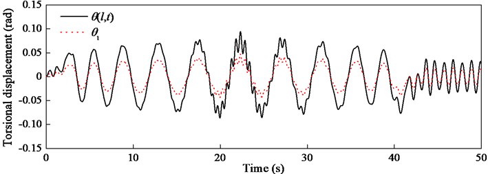
Fig. 3Lateral displacements y1 and y2 at different times with λ= 0.5
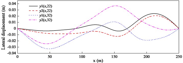
Fig. 4Torsional displacements θl,t and θ1 with λ= 10-5
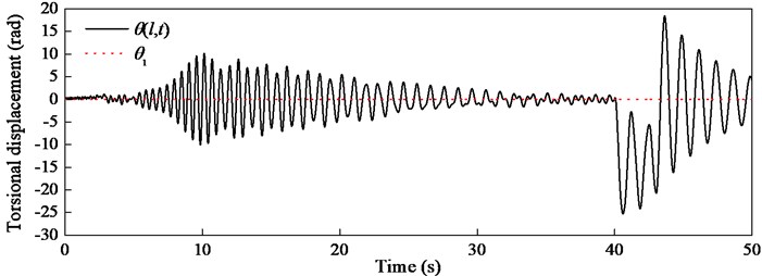
In order to simulate the free spinning swivel, should be zero, however, this will result in the singular matrix in Eq. (16). Thus, a fairly small number 10-5 is adopted. The torsional displacements of the lower end of the hoisting cable and the bucket are shown in Fig. 4. It can be observed that the torsional displacement of the bucket is almost zero. So are the lateral displacements of two guiding cables and , and almost keep pace with each other, which is shown in Fig. 5. By comparing Fig. 4 with Fig. 2, on the one hand, the torsional displacement in the free spinning swivel is much larger than that in the proportional swivel, on the other hand, there is one resonance at 10 s in Fig. 4.
The longitudinal displacements with three kinds of swivels are compared and shown in Fig. 6. Fig. 6 indicates there is no difference in longitudinal vibration between the self-locking swivel and the proportional one, and there is one resonance at 23 s. However, the longitudinal displacement with the free spinning swivel is obviously different and the resonance occurs at 10 s, which implies the system frequencies decrease.
Fig. 5Lateral displacements y1 and y2 at different times with λ= 10-5
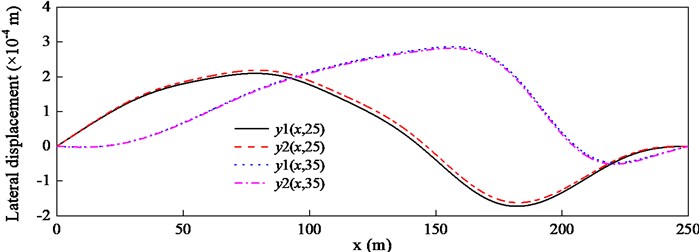
Fig. 6Longitudinal displacements u1 with different λ
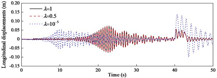
Fig. 7Torsional displacements ul/2,t calculated from two models
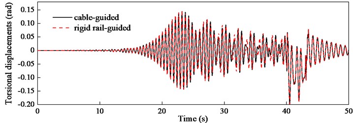
The presented theoretical model is derived from the cable-guided hoisting system, however, it would be excited if the model could be also applied to the rigid rail-guided hoisting system, such as the elevator system. The preloads and are increased to 108 N so that the guiding cables look like the rigid guide rail. The torsional displacement of the middle of the hoisting cable calculated using the presented model with 30 is compared with that from the rigid rail-guided model in Fig. 7. Although the trial functions in Eq. (12) in two models are different, the excellent agreement indicates the presented model is generic and universal.
4. Conclusions
The coupled longitudinal-torsional responses of the hoisting cable with time-varying length in the cable-guided hoisting system are investigated. The vibration model is established by introducing a coefficient , which represents the free spinning, proportional and self-locking swivels when varying from 0 to 1. Especially, 10-5 or 10-6 is recommended for the free spinning swivel, otherwise, will be a singular matrix. The presented theoretical model could also be used to describe the coupled vibration in the rigid rail-guided hoisting system but needs more modes.
References
-
Ma C., Xiao X. M. Kinetic analysis of a multi-rope friction mine hoist under overload conditions. Journal of Vibroengineering, Vol. 15, Issue 2, 2013, p. 925-932.
-
Zi B., Qian S., Ding H. F., Andres K. Design and analysis of cooperative cable parallel manipulators for multiple mobile cranes. International Journal of Advanced Robotic Systems, Vol. 9, 2012, p. 1-10.
-
Zhu W. D., Ren H. A linear model of stationary elevator traveling and compensation cables. Journal of Sound and Vibration, Vol. 332, Issue 12, 2013, p. 3086-3097.
-
Wang P. H., Fung R. F., Lee M. J. Finite element analysis of a three-dimensional underwater cable with time-dependent length. Journal of Sound and Vibration, Vol. 209, Issue 2, 1998, p. 223-249.
-
Kaczmarczyk S., Ostachowicz W. Transient vibration phenomena in deep mine hoisting cables. Part 1: Mathematical model. Journal of Sound and Vibration, Vol. 262, Issue 2, 2003, p. 219-244.
-
Zhang P., Zhu C. M., Zhang L. J. Analysis of forced coupled longitudinal-transverse vibration of flexible hoisting system with varying length. Engineering Mechanics, Vol. 25, Issue 12, 2008, p. 202-207.
-
Ren H., Zhu W. D. An accurate spatial discretization and substructure method with application to moving elevator cable-car systems. Part 2: Application. Journal of Vibration and Acoustics, Transactions of the ASME, Vol. 135, Issue 5, 2013, p. 051037.
-
Samras R. K., Skop R. A., Milburn D. A. Analysis of coupled extensional torsional oscillations in wire rope. Journal of Engineering for Industry, Vol. 96, 1974, p. 1130-1135.
-
Hashemi S. M., Roach A. A dynamic finite element for vibration analysis of cables and wire ropes. Asian Journal of Civil Engineering, Vol. 7, Issue 5, 2006, p. 487-500.
-
Shao X. G., Zhu Z. C., Wang Q. G., Chen P. C., Zi B., Cao G. H. Non-smooth dynamical analysis and experimental validation of the cable-suspended parallel manipulator. Proceedings of the Institution of Mechanical Engineers, Part C: Journal of Mechanical Engineering Science, Vol. 226, Issue 10, 2012, p. 2456-2466.
-
Verreet R., Ridge I. M. L. The use of swivels with steel wire ropes. OIPEEC Round Table Conference, Bethlehem, USA, 2001.
-
Lanczos C. The Variational Principles of Mechanics. Dover Publications, New York, 1986.
-
Ilchmann A., Reis T. Surveys in Differential-Algebraic Equations 2. Springer-Verlag, Berlin, Germany, 2015.
About this article
This work is supported by the National Natural Science Foundation of China (51475456), Program for New Century Excellent Talents in University (NCET-13-1017) and the Priority Academic Program Development of Jiangsu Higher Education Institutions (PAPD).
