Abstract
The aim of the paper is to present a planetary gearbox for wind turbine. At constant wind power input the planetary gearbox is able to provide variable speed of the output shaft. The main purpose of the differential transmission is on the capability to adapt the operation to variable loading of wind. A CAD model has been proposed in order to investigate the operation feasibility of the proposed design solution. A proper dynamic model has been developed in ADAMS software. Simulation tests have been carried out and results are discussed to validate the proposed design solution.
1. Introduction
Gearboxes are used in various types of industrial machinery to provide suitable torque while reducing speed from a rotating power source by using gear ratios. Gearboxes are used in many applications, such as wind turbines, conveyors, draglines, bridges and many other machines. Gears also are used in differential drives of automobiles, final drives of tractors and heavy machineries mainly as reducer. The efficiency of gear trains depends on many factors such as the type and profile of teeth profile, contact stresses, number and type of bearings. These factors have been studied with recent approaches in [1-4]. Planetary gear transmissions are commonly used in applications where a large speed reduction is required as pointed out in [4, 5]. Several design solutions have been proposed in the literature, like for example in [6-10]. General design characteristics have been selected for practical applications of the transmission, like for example, in wind turbine installations. A wind turbine installation can be identified by referring to a small wind turbine of 10 kW power and with average wind speeds of 10-25 m/s.
2. A kinematic model of a new planetary gearbox
The proposed new planetary transmission can be considered as a CVT (solution). It consists of a mechanical planetary gear set. In this research work a new solution is considered for improving the efficiency of planetary transmissions. This mechanism has two mobile planetary gear sets with an asymmetrical design, Fig. 1. The asymmetrical design gives special operation features. The special operation features can be recognized in smoothly changing reduction ratio depending on the load of output shaft. A kinematic characterization of the mechanism can be expressed as function of parameters of external torques , on the carriers and constant input angular velocity ,, Fig. 1. The kinematic relations among the angular velocities of the gears with 1, 2, 3, 4, 5, 6 teeth can be expressed in the form:
where and:
when are the number of teeth in the gear (1,.., 6). From Eqs. (1) and (2) angular velocities , of gears 3 and 1 can be obtained as:
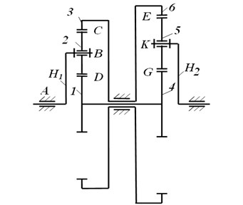
Fig. 1A kinematic scheme for the new planetary gear box: longitudinal view with H1 – input carrier, 1 – input sun gear, 2 – input satellite, 3 – input epicyclic gear, 4 – output sun gear, 5 – output satellite, 6 – output epicyclic gear, H2 – output carrier
3. Adams model
Virtual design of the proposed planetary gearbox with 2-DOFs has been done in ADAMS software. An input angular velocity and output torque have been specified. The constant speed of motor with value of 400 rpm has been applied to the input carrier. An external torque with a constant value of 45 Nm has been applied to the output shaft of planetary gearbox. The proposed design of planetary gear transmission is shown in Fig. 2. Simulation of the gearbox has been proposed in order to investigate the engineering feasibility of the proposed design solution. The main dimensions can be as equal to a maximum high of 150 mm, a maximum longitudinal size of 200 mm and maximum width of 160 mm. The pressure angle of teeth of gears is 20 degrees. All gears are made from steel Cr 40 and carriers, spindles, shafts are made from steel C45, except standard parts such as bearings, washers, nuts, bolts and screws. The gears have been made with module of 1 mm. The output and input shafts have different diameters of 14 and 30 mm correspondingly.
4. Simulation modes
Input parameters for the simulation of a planetary gear transmission have been defined. Input angular speed of motor and torque have been given as a constant values of 400 rpm and 15 Nm. Output torque is variable in range from 1 up to 8 Nm. Friction coefficient of gears has been set as equal to 0.2 by referring to a contact of steep surfaces. Table 1 shows main other parameters that have been assumed by referring to feasible values for a real case of study considering material, penetration depth and force exponent.
During the simulation of model the output parameters such as angular velocity, torque contact forces have been computed in order to investigate the dynamic behavior of the proposed transmission. Tests have been carried out by considering a constant input speed as 400 rpm and torque as 15 Nm and variable output torque as 1-8 Nm. When a variable torque is applied to the output shaft of planetary gearbox the input shaft has to rotate continuously with the constant speed of motor of 400 rpm. If this process will happen then it means the planetary gear box works with 2 degrees of freedom and changes reduction ratio.
Fig. 2The ADAMS model of the final design with reference frames and applied loads
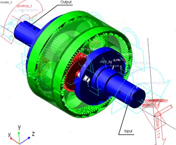
Table 1Input parameters for simulation of model in Fig. 2
Parameter | Valve | Units |
Input angular velocity | 400 | rpm |
Input torque | 15 | Nm |
Output angular velocity | Plots in Fig. 3 | rpm |
Output torque | Variable (1-8) | Nm |
Damping | 10 | N∙sec/mm |
Young’s modulus | 2.07 E+005 | N∙mm2 |
Density | 7.801 E-006 | Kg/mm3 |
Penetration depth | 0.1 | mm |
Force exponent | 1.8 |
5. Simulation results
The variable torque has been applied in order to check feasibility of change reduction ratio automatically. The proposed planetary gear transmission can to adapt to externally applied variable load to the output shaft by smoothly changing reduction ratio. In this paper, dynamic simulations are carried out with the aim to check the feasibility of the proposed gearbox for wind turbine installation. The results of dynamic simulation have been obtained and presented in the plots of Figs. 3 to 8.
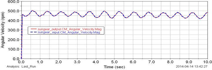
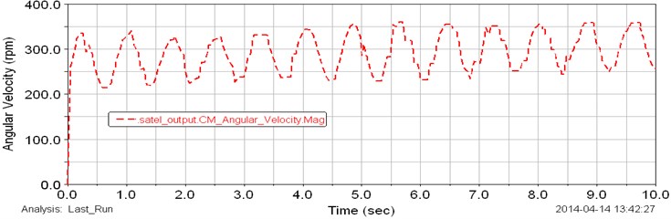
Angular velocities of the input and output shafts of planetary gear transmission are presented in Fig. 3. The input angular velocity has been given as a constant speed of motor of 400 rpm. As shown in the plot of Fig. 3 the input angular speed is constant during the test. The output angular velocity with approximately average value of 425 rpm is presented in Fig. 3 (red line). By considering the plot in Fig. 3 the output speed changes from 400 up to 450 rpm during the test. This is because, the variable torque has been applied to the output shaft of gearbox. The generated variable torque is presented in Fig. 4. MSC ADAMS generates cyclic different values of torque from 1 up to 8 Nm during the test. This torque change affects to the output angular velocity. The input shaft of the planetary gear transmission rotates with constant speed and it can be observed in Fig. 3 and 4. Fig. 5 shows the plot of computed angular velocities of the input and output sun gears (red and blue dot lines). The input and output sun gears rotate with same angular speeds. Results show that the angular speeds of sun gears change from 450 up to 500 rpm during the simulation. Computed torque of the sun gear is presented in Fig. 6. The torque change from 1 up to 4 Nm. The curve in the plot is cyclic. Computed plot of the angular speed of the input planet gears is presented in Fig. 7. The angular velocity of input planet gears is approximately 375 rpm. Fig. 8 shows computed plot of angular speeds of output planet gears. The speed changes from 225 up to 350 rpm and curve in the plot is cyclic.
Fig. 3Computed plot of the angular speed of the input and output shafts
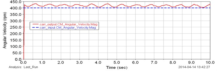
Fig. 4Applied variable torque to the output shaft
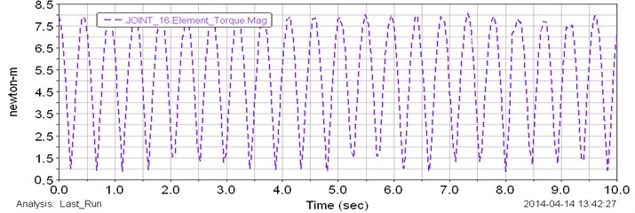
Fig. 5Computed plot of the angular speed of the input (blue line) and output (red line) sun gears
The variable load which has been applied to the output shaft is cyclic as shown in Fig. 4 and this cyclic load affected to the output results. By considering Figs. 3-8 it is possible to say the planetary gearbox can adapt to external applied load. The input shaft rotates constant angular speed. The smoothly cyclic curves in the plots show that the system can smoothly change reduction ratio.
By considering these results of study of a planetary gearbox with a virtual models it is possible to identify that the mechanism can adapt to a variable external load. The simulation results show that the proposed planetary gearbox has suitably output parameters both in terms of speed and torque. Results with the preliminary model show that the gearbox has a constant output values, when the constant load has been applied to the system. Results with the final model of planetary gear transmission show that the planetary gear box has capability to adapt to a variable load. In this study simulation results show that the gearbox smoothly changes the reduction ratio at constant input speed. It means the input shaft rotates with a constant angular speed of motor.
Fig. 6Computed plot of the torque of the sun gears
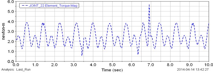
Fig. 7Computed plot of the angular speed of the input planet gears
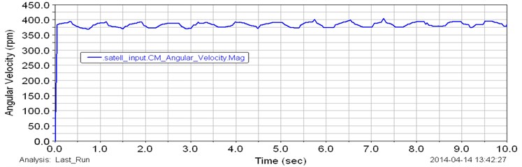
Fig. 8Computed plot of the angular speed of the output planet gears
6. Conclusion
A planetary gear box with two degrees of freedom has been studied from aspects of mechanical design and kinematic modeling. A mechanical design and 3D CAD model of a planetary gear box with two degrees of freedom have been proposed in order to adapt the operation to variable loading. Design of the planetary gearbox is shown in kinematic scheme. In order to check the feasibility of the design a dynamic simulation of the planetary gearbox has been carried out in ADAMS software. Simulation results show that the proposed planetary gear box has suitably constant output values both in terms of speed and torque. The simulation results also show that the proposed gear box smoothly changes the reduction ratio at constant input speed. The main achievement of this work is the new design for a new planetary gearbox with 2DOFs which can generate a variable reduction ratio. Results are suitable for using the proposed design in wind turbine applications.
References
-
Fetvaci C. Definition of involute spur gear profiles generated by gear-type sharper cutters. Mechanics Based Design of Structures and Machines, Vol. 38, Issue 4, 2010, p. 481-492.
-
Kaharman A., Ding H. A methodology to predict surface wear of planetary gears under dynamic conditions. Mechanics Based Design of Structures and Machines, Vol. 38, 2010, p. 493-515.
-
Patel P. Design and Analysis of Differential Gearbox. Report, U.V. Patelcolliege of Engineering, Ganpat University, Kherva, 2009.
-
Thirumurugan R., Muthuveerappan G. Critical loading points for maximum fillet and contact stresses in normal and high contact ratio spur gears based on load sharing ratio. Mechanics Based Design of Structures and Machines, Vol. 39, Issue 1, 2011, p. 118-141.
-
Muni D. V., Muthuveerappan G. A comprehensive study on the asymmetric internal spur gear drives through direct and conventional gear design. Mechanics Based Design of Structures and Machines, Vol. 37, Issue 4, 2009, p. 431-461.
-
Balbayev G., Ceccarelli M. Design and characterization of a new planetary gear box. Mechanisms, Transmissions and Applications, Mechanisms and Machine Science, Vol. 17, 2013, p. 91-98.
-
Balbayev G., Carbone G. A dynamic simulation of a novel continuous variable transmission. Proceedings of the 11th IFToMM International Symposium on Science of Mechanisms and Machines, Vol. 18, 2013, p. 109-116.
-
Carbone G., Mangialardi L., Bonsen B., Tursi C., Veenhuizen P. A. CVT dynamics: theory and experiments. Mechanism and Machine Theory, Vol. 42, 2007, p. 409-428.
-
Derek F. L., Dennis W. H. The operation and kinematic analysis of a novel cam-based infinitely variable transmission. ASME International Design Engineering Technical Conferences and Information in Engineering Conference, Philadelphia, Vol. 3, 2006, p. 1-6.
-
Yaghoubi M., Mohtasebi S. Design and simulation of a new bevel multi-speed gearbox for automatic gearboxes. Science Journal Report and Opinion, Vol. 2, 2010, p. 1-7.
About this article
