Abstract
Considering the unstable oscillation in the rolling process caused by the lubrication conditions change, a dynamic rolling process model considering the nonlinear friction is built using the Bland-Ford-Hill rolling force model. In addition, based on the structure model which can characterize the coupling vibration of rolling mill, and taking the dynamic variations of rolling force and rolling torque as the feedback excitation, the rolling mill vertical-torsional-horizontal coupled dynamic model under nonlinear friction is established. On this basis, the system Hopf bifurcation points at different rolling speeds are calculated by Hurwitz algebraic criterion. And the system stability domain is determined by analyzing the eigenvalue of the system. Finally, using the parameters of a 2030 cold rolling mill, the correctness of the bifurcation point calculation and the stability domain analysis are verified by numerical simulation. The results show that the system stability domain is enclosed by the instability critical lines of vertical vibration modal, torsional vibration modal and horizontal vibration modal. And under different conditions, the system Hopf bifurcation induced by the variation of the friction coefficient can cause system instability with different vibration modals. The study can help to optimize the rolling process, and achieve a reasonable dynamic modification strategy of the rolling mill structure as well.
1. Introduction
The vibration commonly exists in the high-speed strip cold rolling mill, and it seriously affects the improvement of product quality and production efficiency, or even leads to production interruption and equipment failure.
In recent years, scholars have done a lot of research on mill vibration, and also have gained abundant achievements. The existing research generally considered that the mill vibration is a kind of self excited vibration due to the coupling of mill structure and rolling process [1]. Therefore, reasonable simplification of the rolling process and reasonable modeling of the mill structure have become key issues to study mill vibration. Ehmann research group [2-5] carried out a series of study which was mainly focused on the below aspects, the modeling of the dynamic rolling process, the analysis of system stability, the continuous rolling and the regenerative chatter. In actual production, the vibration of the high-speed rolling mill always appears as the coupling of multiple modal vibrations. Paton [6] confirmed the coupling of vertical vibration and horizontal vibration by rolling mill vibration experiments. Yan et al. [7] studied the coupling characteristics of vertical vibration and torsional vibration using the finite element model. Swiatoniowski [8] investigated the characteristic of the vertical-torsional coupling vibration by taking the interaction between plastic deformation process and rolling mill vibration into consideration. In addition, rolling mill system is a typical nonlinear system. Nonlinear stiffness and nonlinear damping of mill structure and nonlinear friction of rolling interface are the most common nonlinear factors studied by scholars. Hou et al. [9] studied the influence of variable friction on vertical-horizontal coupling vibration characteristics of strip mills by means of multi-scale method. Liu et al. [10] indicated that the nonlinear friction may induce the Hopf bifurcation of the rolling mill drive system, and cause the instability of the system. However, due to the friction coefficient in the dynamic rolling process model was usually taken as a constant, the study of the rolling mill coupling vibration with the consideration of the dynamic rolling process model and the nonlinear friction simultaneously is lacked and necessary.
Reference [11], for one thing, has constructed a coupling vibration model of the mill structure, in which vertical vibration, torsional vibration, horizontal vibration and the chatter of the rolled pieces can be well indicated. For another, based on the Bland-Ford-Hill rolling force model, a dynamic rolling process model has also been formulated, in which the dynamic changes of the roll gap in the state of vibration were considered. In this study, on the basis of the models mentioned above, and taking the nonlinear friction coefficient into consideration, a vertical-torsional-horizontal coupling nonlinear dynamic model of the rolling mill is established. According to the dynamical bifurcation theory, the system stability and instability mechanism are analyzed. The results can provide a theoretical basis for restraining and controlling rolling mill vibration.
2. Vertical-torsional-horizontal coupling vibration model of the rolling mill
2.1. Dynamic model of rolling process under nonlinear friction
The geometry of the roll bite is illustrated in Fig. 1, where and are the original geometrical centers of the top and bottom rolls (before vibrations begin). and are the ever-changing centers of the rolls. is the displacement of the horizontal vibration. is the displacement of the vertical vibration. and are the thickness of the strip at entry and exit. is the roll gap spacing measured along the centerline , . , and are the entry position, neutral point position and exit position measured from the centerline . is the horizontal projection length of the contact arc, . R and are the radius of the original top work roll and the deformed top work roll. is the inlet angle, . is the outlet angle, . is the neutral angle. and are the tensile stress of the strip at entry and exit. and are the velocity of the strip at entry and exit. is the roll peripheral velocity. And it is assumed that the width of the strip at entry and exit are . In addition, the parameter with superscript like “” represents the value of the parameter “” under steady state.
For cold rolling, Sims and Arthur [12] indicated that the friction coefficient along the contact arc can be approximately expressed as Eq. (1), when the rolling speed is greater than 0.25 m·s-1:
where, , and are constants, which are related to lubricating oil viscosity, lubricating oil concentration and systems lubrication state. And , , . is the roll peripheral velocity during vibration, . is the angular velocity of the torsional vibration.
For convenience, the friction coefficient near the steady roll peripheral velocity has been deduced by Taylor series expansion:
The Hill simplified formula of Bland-Ford rolling force model is as follows:
where, is the mean tensile stress, usually taking . is the stress state factor, . is the reduction ratio, . is the mean deformation resistance, . and are the coefficients associated with the carbon content of the strip. is the mean total deformation extent, . is the total deformation extent at the entry of this mill stand, . is the total deformation extent at the exit of this mill stand, . is the initial strip thickness entering the first mill stand in a tandem mill configuration. and are coefficients, usually taking 0.4, 0.6.
The change of the roll gap will cause the fluctuation of the strip velocity, and then result in the fluctuation of the strip tensile stress. The tensile stress variations at entry and exit can be expressed as:
where, is the Young’s modulus of the strip. and are the distances from this stand to the upstream stand and the downstream stand. The strip velocities at entry and exit, the strip entry position, exit position and neutral point position can be obtained based on the geometry of the roll bite, the metal flow equation and the equilibrium conditions of the force in the rolling deformation zone [11]:
Fig. 1Roll bite geometry during vibration
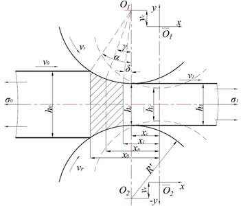
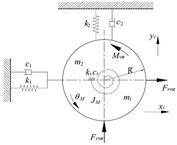
Fig. 2Simplified vertical-torsional-horizontal coupling structure model
According to the force relationship in the rolling deformation zone, the rolling torque and the force acting on the rolls in and directions are given by:
By using Taylor series expansion, the variations of , , , and are as follows:
All the coefficients in Eq. (7) are given in Appendix A.
2.2. Structure model of vertical-torsional-horizontal coupling vibration
The vertical-torsional-horizontal coupling dynamic model of mill structure is schematically presented in Fig. 2. is the equivalent mass of the top work roll. is the lumped equivalent mass of the top work roll, top backup roll and upper mill housing, which is simplified to the center of the top work roll. is the equivalent rotational inertia of the upper rolls, including the top work roll and the top backup roll. , are the horizontal equivalent stiffness and horizontal equivalent damping of the unilateral frame of the mill housing and the support from the top backup roll to the top work roll due to the offset between them. , are the vertical equivalent stiffness and vertical equivalent damping of the frame and the upper beam of the mill housing. , are the torsional equivalent stiffness and torsional equivalent damping of the top main drive system.
As Eq. (4) has the integral terms of time, taking Eq. (4) a derivative with respect to time. Thus the differential equations can be written as:
3. Hopf bifurcation condition and algebraic criterion
When lubrication conditions between roller and strip changed, vibration of rolling mill system can lose stability by some bifurcation ways. Hopf bifurcation is an important bifurcation phenomenon [13, 14]. And it is closely linked with vibration in engineering projects. Early studies have shown that the instability of rolling process is mainly caused by Hopf bifurcation of the system. Therefore, it is of great engineering significance to analyze the Hopf bifurcation characteristic of the mill vertical-torsional-horizontal coupling vibration system.
In order to determine system stability through Hopf bifurcation analysis, it is necessary to clarify the Hopf bifurcation condition and its algebraic criterion. Using to substitute , and rewritten the form of Eq. (8) like as shown in Eq. (9), where is the bifurcation parameter, :
Through the analysis, the equilibrium point of this system is the coordinate origin, and the Jacobian matrix at this point is as follows:
For a pair of conjugate complex eigenvalue of the Jacobian matrix, , if the conditions , and are satisfied when , and simultaneously real parts of other eigenvalue are all negative, Hopf bifurcation phenomenon can occur and is the bifurcation point.
The characteristic equation of Jacobian matrix can be expanded as an algebraic polynomial equation:
A series of Hurwitz determinants can be constructed by the coefficients as follows:
here, 0 when 8.
The necessary and sufficient conditions for the Hopf bifurcation phenomenon to occur at point judging by Hurwitz determinants are expressed as:
4. System stability domain
4.1. Calculation of bifurcation parameters and analysis of system stability
Taking the 4th stand of a 2030 five-stand tandem cold mill as an example [15], the parameters of this mill are: , , 1.206 m, , , 810 MPa, 0.29, 2 mm, 4.75 m, 4.75 m, 0.3 m, 0.5335 m, 210 GPa, 0.04, 9200 kg, 203200 kg, 1381 kg·m2, 1×10⁹ N·m-1, 6.9×10¹⁰ N·m-1, 7.9×10⁶ N·m/rad, 5×10⁴ N·s·m-1, 1.64×10⁷ N·s·m-1, 4178 N·m·s·rad-1. For this mill, the frequencies of vertical vibration modal, torsional vibration modal and horizontal vibration modal are about 133 Hz, 12.5 Hz and 52 Hz, respectively.
Fig. 3The trend of bifurcation parameter b* with steady rolling speed v-r
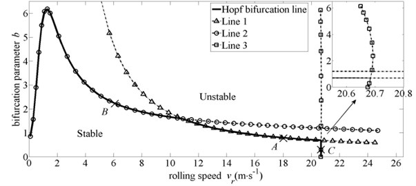
Fig. 3 shows the distribution of Hopf bifurcation parameter under different steady rolling speed . It is observed that the system Hopf bifurcation line is spliced by Line 1, Line 2 and Line 3. And these three lines represent the instability critical value of horizontal vibration modal, torsional vibration modal and vertical vibration modal, respectively. Taking three points on these three lines randomly (point , point and point in Fig. 3), and their eigenvalue are listed in Table 1. As shown in Table 1, for 18 m·s-1, all the eigenvalue of the system have the negative real parts when 0.7982, which means the system is stable at the moment. When 0.7982, a pair of pure imaginary eigenvalue appeared in the system, (–0.0000±3.2682i)×102, and this pair of conjugate eigenvalue represent the characteristic of horizontal vibration modal, which means that the horizontal vibration mode is in the critical state at this time. However, when 0.7982, the real parts of eigenvalue become positive, in other words, the horizontal vibration modal loses its stability. Therefore, Line 1 is the critical boundary of horizontal vibration modal. Similarly, Line 2 is the critical boundary of torsional vibration modal. Line 3 is the critical boundary of vertical vibration modal. And the system stability domain is enclosed by the coordinate axes and the system Hopf bifurcation line.
Table 1Eigenvalue about the critical parameters
(m·s-1) | (×102) | (×102) | (×102) | (×102) | (×102) | ||
18.00 | A+ | 0.8200 | –0.1815±8.3787i | 0.0008±3.2674i | –0.0339±0.7868i | –2.6399 | –0.9583 |
A | 0.7982 | –0.1816±8.3783i | –0.0000±3.2682i | –0.0355±0.7870i | –2.6347 | –0.9593 | |
A- | 0.7800 | –0.1816±8.3779i | –0.0007±3.2689i | –0.0369±0.7871i | –2.6303 | –0.9601 | |
6.00 | B+ | 2.2700 | –1.8620±8.0343i | –0.0146±3.2511i | 0.0008±0.8035i | –0.9738 | –0.2893 |
B | 2.2541 | –1.8622±8.0342i | –0.0147±3.2515i | –0.0000±0.8040i | –0.9719 | –0.2894 | |
B- | 2.2400 | –1.8624±8.0341i | –0.0148±3.2518i | –0.0007±0.8046i | –0.9703 | –0.2895 | |
20.68 | C+ | 0.3500 | –0.0001±8.4156i | –0.0153±3.2852i | –0.0629±0.7824i | –2.8909 | –1.1405 |
C | 0.2885 | –0.0000±8.4143i | –0.0182±3.2876i | –0.0676±0.7824i | –2.8742 | –1.1447 | |
C- | 0.2200 | 0.0001±8.4128i | –0.0214±3.2901i | –0.0729±0.7824i | –2.8555 | –1.1494 | |
In Fig. 3, with the increase of rolling speed, Line 1 decreases gradually. Because under the same variations of the roll gap, the larger the rolling speed is, the bigger the tensile stress fluctuates. And the variation of force acting on the rolls in direction is also greater. Thus, the stability of horizontal vibration modal reduces accordingly. For torsional vibration modal, according to Eq. (3) and Eq. (6), the expression of rolling torque can be rewritten as: Under the same variations of the roll gap, the fluctuations of parameters , , , , , , and have no relationship with rolling speed. But the fluctuation of the mean tensile stress increases with the increase of rolling speed. On the contrary, the fluctuation of the neutral angle decreases with the increase of rolling speed. This may make the variation of rolling torque have a minimum value at a certain rolling speed. Hence, the stability of torsional vibration modal increases first and then reduces as the rolling speed increases. For vertical vibration modal, the effect of the friction coefficient variation on the rolling force fluctuates is small, so only when the vertical vibration modal is close to the critical state, the effect of the friction coefficient variation on the stability of vertical vibration modal can be reflected explicitly. And the bifurcation parameter would change sharply with the change of rolling speed. In addition, rewritten the force acting on the rolls in direction (Eq. (6)) as: . Under the same variations of the roll gap and the same rolling speed, the fluctuations of the mean tensile stress and the stress state factor increase with the increase of parameter , but the fluctuation of exit position decreases at the same time. Similarly, with the change of parameter , the variation of force acting on the rolls in direction may have a minimum. Therefore, the stability of vertical vibration modal increases first and then reduces as the parameter increases, but this effect is small.
Through further analyze the Fig. 3, it can be seen that there are three cross points on the curves in the figure, their abscissa is 10.9 m·s-1, 20.684 m·s-1 and 20.675 m·s-1, respectively. When 10.9 m·s-1, the system Hopf bifurcation induced by the variation of friction coefficient may first result in torsional vibration modal instability. And torsional vibration modal will extend rapidly in the mill system. Finally, the whole mill system will lose its stability. When 10.9 m·s-120.675 m·s-1, the system Hopf bifurcation induced by the variation of friction coefficient could first cause horizontal vibration modal instability. Similarly, horizontal vibration modal will spread rapidly in the mill system, and eventually lead to the instability of the entire mill system. For 20.675 m·s-120.684 m·s-1, a narrow area is enclosed by Line 1 and Line 3, and only when the value of parameter b is in this narrow area, the system is stable. If the value of parameter moves toward the outside of this area and crosses Line 3, the system Hopf bifurcation would give rise to the vertical vibration modal instability. And then the instability of the whole mill system would occur, which was induced by the vertical vibration modal. Another hypothesis, if the value of parameter moves toward the outside of this area and crosses Line 1, the system Hopf bifurcation would cause the horizontal vibration modal instability. And the mill system would become overall instability because of the horizontal vibration modal. Finally, when 20.684 m·s-1, the vertical vibration modal will always be in the unstable state, the system Hopf bifurcation will not occur again. And this critical speed has also been confirmed by field test.
4.2. Dynamic response of the system at the bifurcation point
Moreover, in order to verify the accuracy of the Hopf bifurcation point calculation and the correctness of the system stability domain analysis, the system motions corresponding to the bifurcation point and its neighborhood are numerically simulated. For an initial disturbance 10-7 m, the simulation results are shown in Figs. 4-6.
Fig. 4Dynamic response of the system for vr= 18 m·s-1 and b= 0.7
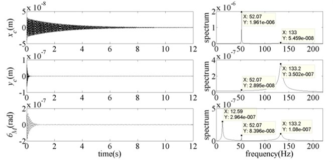
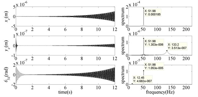
Fig. 5Dynamic response of the system for vr= 18 m·s-1 and b= 0.7982
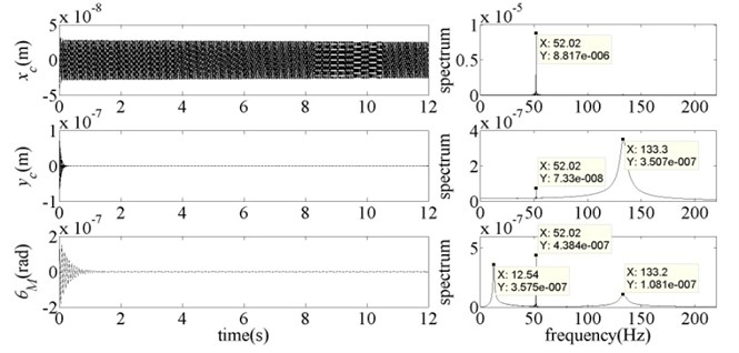
As shown in Fig. 4, when 0.7, which is less than the instability critical value 0.7982, the system was stable. At the moment, each subsystem was in the state of free vibration, mainly with their own modal frequency. As the system vibration was caused by the initial disturbance of the vertical subsystem, hence, the vibration of torsional subsystem and horizontal subsystem contained the frequency component of vertical vibration modal (133 Hz). In addition, the parameter has been very close to the Hopf bifurcation point which can lead to the instability of horizontal vibration modal, so the frequency component of horizontal vibration modal (52 Hz) can be found in vertical subsystem and torsional subsystem. In Fig. 5, parameter was equal to the instability critical value 0.7982, the horizontal subsystem was in the critical stable state. And the energy of horizontal vibration modal frequency component increased significantly in each subsystem. With the continued increase of parameter (Fig. 6), these three subsystems all lost their stability. At the moment, the main vibration form of each subsystem was horizontal vibration modal. And the energy of this vibration modal increased sharply. In other words, the instability of the whole mill system occurred by the way of horizontal vibration modal. Therefore, the calculation results and the analysis conclusions in Section 4.1 were proved to be correct.
Fig. 6Dynamic response of the system for vr= 18 m·s-1 and b= 0.9
Further studies indicate that the system stability domain mentioned above changes with the change of rolling process parameters and mill structure parameters. Therefore, it is meaningful to carry out a systematic study on the movement laws of these three critical lines due to the change of rolling process parameters and mill structure parameters. And these laws can provide the technique support for dynamic modification (designing) of mill structure and the orientation (method) of rolling process parameters formulating.
5. Conclusions
This paper has constructed a rolling mill vertical-torsional-horizontal coupled dynamic model with the consideration of nonlinear friction. And the system Hopf bifurcation points at different rolling speed have been calculated by using Hurwitz algebraic criterion. The following conclusions are drawn:
1) The stability domain of the rolling mill system is enclosed by the instability critical line of vertical vibration modal, torsional vibration modal and horizontal vibration modal.
2) Under different conditions, the system Hopf bifurcation induced by lubrication conditions change between roller and the rolled pieces can cause system instability with different vibration modals. When the rolling speed is low, the instability of the mill system is mainly caused by torsional vibration modal. When the rolling speed is high, the instability of the mill system is mainly caused by vertical vibration modal. When the rolling speed is in the middle speed segment, the instability of the mill system is mainly caused by horizontal vibration modal.
3) With the change of rolling process parameters and mill structure parameters, the system stability domain changes as well. Studying the effect of various parameters on the stability domain boundaries can provide a theoretical basis and reference for formulating rolling process parameters and achieving structural dynamic modification strategies.
References
-
Gao Z. Y., Zang Y., Zeng L. Q. Review of chatter in the rolling mills. Journal of Mechanical Engineering, Vol. 51, Issue 16, 2015, p. 87-105.
-
Yun I. S., Wilson W. R. D., Ehmann K. F. Chatter in the strip rolling process. Part 1: Dynamic model of rolling, Part 2: Dynamic rolling experiments, Part 3: Chatter model. Journal of Manufacturing Science and Engineering, Vol. 120, Issue 5, 1998, p. 330-348.
-
Hu P. H., Ehmann K. F. A dynamic model of the rolling process. Part 1: Homogeneous model, Part 2: Inhomogeneous model. International Journal of Machine Tools and Manufacture, Vol. 40, Issue 1, 2000, p. 1-31.
-
Hu P. H., Zhao H. Y., Ehmann K. F. Third-octave-mode chatter in rolling. Part 1: Chatter model, Part 2: Stability of a single-stand mill, Part 3: Stability of a multi-stand mill. Proceedings of the institution of Mechanical Engineers, Part B: Journal of Engineering Manufacture, Vol. 220, Issue 8, 2006, p. 1267-1303.
-
Zhao H. Y., Ehmann K. F. Stability analysis of chatter in tandem rolling mills. Part 1: Single- and multi-stand negative damping effect, Part 2: The regenerative effect. Transactions of the ASME: Journal of Manufacturing Science and Engineering, Vol. 135, Issue 3, 2013, p. 1-19.
-
Paton D. L., Critchley S. Tandem mill vibration: its cause and control. Iron and Steel Making, Vol. 12, Issue 3, 1985, p. 37-43.
-
Yan X. Q., Shi C., Cao X., et al. Research on coupled vertical-torsion vibration of mill-stand of CSP mill. Journal of Vibration, Measurement and Diagnosis, Vol. 28, Issue 4, 2008, p. 377-381.
-
Swiatoniowski A. Interdependence between rolling mill vibrations and the plastic deformation process. Journal of Materials Processing Technology, Vol. 61, Issue 4, 1996, p. 354-364.
-
Hou D. X., Peng R. R., Liu H. R. Vertical-horizontal coupling vibration characteristics of strip mill rolls under the variable friction. Journal of Northeastern University (Natural Science), Vol. 34, Issue 11, 2013, p. 1615-1619.
-
Liu B., Liu S., Zhang Y. K., et al. Bifurcation control for electromechanical coupling vibration in rolling mill drive system based on nonlinear feedback. Journal of Mechanical Engineering, Vol. 46, Issue 8, 2010, p. 160-166.
-
Zeng L. Q., Zang Y., Gao Z. Y., et al. Study on overall coupled modeling of the rolling mill. Journal of Mechanical Engineering, Vol. 51, Issue 14, 2015, p. 46-53.
-
Sims R. B., Arthur D. F. Speed-dependent variables in cold strip rolling. Journal of Iron and Steel Institute, Vol. 172, Issue 3, 1952, p. 285-295.
-
Lee B. H. K., Price S. J., Wong Y. S. Nonlinear aeroelastic analysis of airfoils: bifurcation and chaos. Progress in Aerospace Sciences, Vol. 35, Issue 5, 1999, p. 205-334.
-
Wen G. L., Xie J. H., Xu D. L. Onset of degenerate Hopf bifurcation of a vibro-impact oscillator. Journal of Applied Mechanics, Vol. 71, Issue 4, 2004, p. 579-581.
-
Zou J. X., Xu L. J. Vibration Control of Cold Tandem Mill System. Metallurgical Industry Press, Beijing, 1998.
About this article
This study is supported by the National Natural Science Foundation of China (No. 51175035), the Ph.D. Programs Foundation of Ministry of Education of China (No. 20100006110024), the Beijing Higher Education Young Elite Teacher Project (No. YETP0367) and the Fundamental Research Funds for the Central Universities (No. FRF-BR-14-006A).
