Abstract
A novel sliding mode observer (SMO) is presented for sensorless control of permanent magnet synchronous machines (PMSM). Compared to conventional sliding mode observers, the sigmoid function is used to weaken chattering problem; Kalman filter is substituted for conventional low-pass filters. Asymptotical stability is analyzed by Lyapunov stability theory. The active-disturbance rejection control (ADRC) speed regulator is designed with a given speed and estimated speed by novel sliding mode observer as inputs and iq* as output. The effect of load in speed loop is regarded as an external disturbance in the ADRC regulator. The disturbance is observed and compensated by ADRC, which leads to good dynamic and static performance and robust to load. Experimental results are provided to verify the feasibility and effectiveness of the proposed method.
1. Introduction
In recent years, PMSM has been vigorously developing because of its advantages in reliability and high efficiency [1-3]. In the high-performance control system of PMSM, the rotor speed and position signals used to achieve closed-loop control are collected by mechanical sensors, which have the disadvantages in high costs, installation difficulties, larger volume and reduced reliability, therefore the research on speed sensorless has a great significance in solving the above problems. The observer – based estimation methods of the position and speed of PMSM are as follows: adaptive observer [4], Kalman filter [5], sliding mode observer [6-9], and so on.
In a conventional sliding-mode observer (SMO), a low-pass filter (LPF) and an additional position compensation of the rotor are used to reduce the chattering problem commonly found in SMOs using a signum function. Currently, a sigmoid function is used for the SMO as a switching function. Most of the observer designs focus on the fast response and high tracking accuracy. For the fast response, the use of a sigmoid function in a boundary layer is popular. However, the observer error cannot be guaranteed to converge to zero within the boundary layer [10-12]. In order to get high tracking accuracy a new sensorless control algorithm that uses a sigmoid function as a switching function with variable boundary layers and without LPF is proposed [13]. And the stator resistance is estimated using an adaptive control scheme to improve the steady-state performance. But variable boundary layers and estimating the stator resistance make the observer complex. This paper proposes a new sensorless control algorithm for a PMSM based on the new SMO which uses a sigmoid function as a switching function with constant boundary layers and Kalman filter. Compared to conventional SMO the novel sliding mode observer proposed in this paper can reduce system chattering and observer error, and algorithm is more simple than that is proposed in reference [13]. Furthermore, the Phase-locked loop (PLL) is used for improving the precision of the rotor speed estimation.
The PID regulator is adopted in the speed loop in the conventional vector control of PMSM. The PID regulator has the advantages in simple structure and good stability, but its parameter robustness cannot meet the requirements of the speed fast response and high steady state precision in the wide speed range. At low speed, the system can't even be normally operated [14]. According to the nonlinear, the multivariable and strong coupling characteristics of PMSM, ADRC speed regulator is proposed in this paper, which is based on feature that the ADRC has a good control effect on time-varying, nonlinear, strong coupling, large time delay object. Compared to the conventional PID speed regulator, ADRC speed regulator achieved the speed fast response and high steady state precision at the same time. The output of ADRC extended state observer does not distinguish between internal and external disturbance in the system, but the sum of them, thus the disturbance can be offset by compensation. It significantly reduces the effects of parameter variations and load disturbances on the system. An experimental platform based on the theoretical analysis is built, and experimental results are provided to verify the correctness of the designed speed sensorless and ADRC control system of PMSM.
2. Models of PMSM
The sliding mode observer is designed under the mathematical model of PMSM in two-phase stationary coordinate system, and the auto disturbance rejection speed regulator is deduced in two-phase rotational coordinate system. The mathematical models of PMSM in two kinds of coordinate system are shown as follows.
2.1. In two-phase stationary coordinate system
The mathematical model of in two-phase stationary coordinate system is:
The equation of back electromotive force is:
where , , , , , are the components of stator current, stator voltage and back electromotive force in axis respectively. is stator resistance; is stator inductance; is the flux of rotor permanent magnet; is the rotor angular velocity; is the rotor angular position.
2.2. In two-phase rotational coordinate system
The mathematical model of PMSM in two-phase rotational coordinate system is:
where , , , are the components of stator current and stator voltage in axis Respectively; , is the inductance of surface-mounted in axis; is the moment of inertia; is the coefficient of friction; is the pole pair of motor; is the load torque.
3. Design of novel sliding observer
Based on the mathematical model and the theory of sliding mode, the switching function is:
where is the estimated value of current; is the actual feedback value of current, choosing the switching surface as:
The equation of state of the current observer is:
In order to weaken chattering problem, sigmoid function is used to substitute sign function. The expressions of , , are:
where is the sliding gain, the sliding gain must be large enough, but the excessive causes chattering noise, resulting in unnecessary estimation error, so the switch gain uses the adaptive law as follows:
The adaptive rate in Eq. (9) can be easily proved to satisfy the stability, where is scale coefficient.
It can be seen that back-EMF is obtained by the first-order low-pass filter in conventional SMO, which leads to phase lag when it is used to calculate the position angle, thus the phase compensation is necessary. In order to overcome the problem, a model with the structure of extended Kalman filter Eq. (11) is designed to obtain the back-EMF and calculate the rotor position angle by Eq. (15). By using this extended Kalman model to obtain back-EMF, harmonic can be removed and the angle with smaller identification error can be obtained. The phase compensation is eliminated by this structure.
Electromagnetic time constant is much smaller than mechanical counterpart, assuming 0, then the model of back-EMF is:
Construct the back-EMF observer:
where is a positive constant, Eq. (12) is derived by subtract Eq. (10) from Eq. (11):
where , , .
Constructing Lyapunov function to verify the stability of Eq. (12):
Putting Eq. (12) into the differential equation of Eq. (13), expression Eq. (14) can be obtained:
Therefore, the designed extended Kalman filter observer is stable. According to the back-EMF obtained by observer, position angle of the motor can be obtained as Eq. (15), thus the phase compensation problem is eliminated:
In order to solve the problem of disturbance in velocity calculated by differentiating the angle, the paper uses Phase-locked loop to obtain the velocity of the motor. The expression based on the mathematical model Eq. (2) of PMSM is:
The angle obtained by back-EMF and the Phase-locked loop speed estimation is utilized to track the actual position angle. The deviation is defined as:
The estimated electric angular velocity obtained by PI regulator, which is used to track the changes of actual position angle after integral operation. The PLL block detecting the rotor speed is as shown in Fig. 1. The inputs of the block are the output of the Kalman filter , , the output is the observation result of rotor electrical angular velocity. The novel sliding mode observer is shown in Fig. 2(b), using sigmoid function to substitute sign function, and PLL to estimate the speed after Kalman filter. The observer have the characteristics of simple structure, insensitive to motor parameters, fast response of speed identification, and avoiding the calculating errors caused by the position angle differential. Conventional sliding mode observer is shown in Fig. 2(a).
Fig. 1Structure diagram of PLL
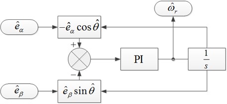
Fig. 2Structure diagram of SMO
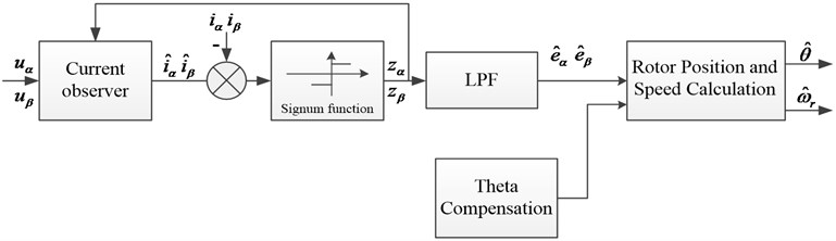
a) Conventional SMO
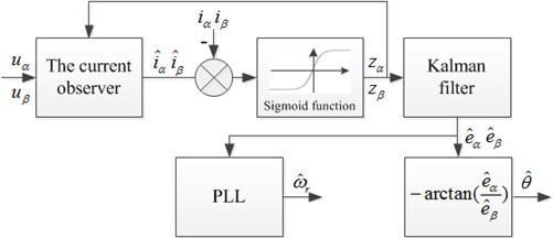
b) The novel SMO
4. ADRC speed controller
4.1. Design of ADRC Speed Controller
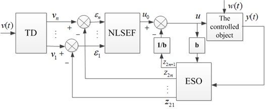
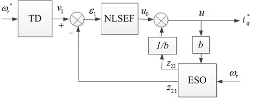
ADRC, consisting of nonlinear tracking differentiator (TD), extended state observer (ESO), nonlinear state error feedback (NLSEF) is a practical nonlinear control synthesis method [15-17]. As for the th order controlled object, the ADRC control structure is as shown in Fig. 3. is a given signal, a smooth signal can be derived from it by a transition progress arranged by TD. And its 1 order differential signal can be obtained as . ESO is utilized to estimate the output of controlled object, which can obtain not only the estimation of each state variables ,…, , but also the real time estimation of internal and external disturbance in system . ,…, , are the error signals between ,…, and ,…, .The initial control signal of controlled object is derived from the NLSEF. After compensating for the real-time disturbance by , the final control value can be obtained, where is the compensation factor.
Fig. 3Block diagram of ADRC
Considering the first-order system:
The first-order system TD is:
The second-order system ESO is:
The NLSEF is:
The nonlinear function can be expressed as:
where is the given signal of ADRC, is the tracking signal of , is the tracking speed factor, is the output of the controlled object, is the tracking signal of , is the estimation value of disturbance, and are the correction gains of output error, , , , are the nonlinear factors, , , are the filter factors, is the gain error. The expression of speed in the mathematical model Eq. (3) in the motor rotating coordinate system can be rewritten as:
It can be seen that the rotation rate is affected by , , . Based on the theory of ADRC, can be regarded as an external disturbance named in speed loop, which can be observed by ADRC to be compensated, so Eq. (23) can be expressed as:
where:
It can be seen from Eq. (25) that the use of ADRC controller can well and effectively estimate the load disturbance and the load sudden change and thus compensate. It is also of good robustness for load. If an ESO can do a good estimation for , then it can restrain the influences caused by the load disturbance.
The structure of PMSM ADRC speed controller is as shown in Fig. 4.
Fig. 4Block diagram of ADRC speed regulator
In Fig. 4, is the given signal of speed, the tracking signal of , is the error signal of speed loop, is the tracking signal of , is the observations of the unknown disturbance signal , is the output of the nonlinear feedback, is the torque current component compensated by the disturbance.
4.2. Stability analysis
4.2.1. 2nd-order ESO error model
Assume that there is a 1st order controlled object:
where is an unknown function, is an unknown disturbance and is the control input.
Set:
System Eq. (26) is extended by one dimension into:
To simplify the calculation, make:
Construct an ESO for Eq. (27) as:
Eq. (28) minus Eq. (27) is the system:
where , , varies within a bounded range and Plane is divided into 5 parts:
Construct piecewise smooth functions respectively for ((0, 1, 2, 3, 4)) as:
It’s easy to prove that is positive definite and continuous on a full plane when it is outside . Parameter selection method is analyzed respectively in the are ((0, 1, 2, 3, 4)), and come to a conclusion , in [18].
4.2.2. Multiple Lyapunov function method
Assume the switch system:
It satisfies the following conditions:
1) Every is globally Lipschitz continuous.
2) Select to make the System switch for finite times in the limited time.
Definition 1. Sequence denotes the switch-to-entry and exit time sequence that subsystem No. corresponds to:
For the strictly increasing time sequence define the Set as a set of all the time sequences that the system runs along Subsystem No. , in which is a non-negative integer.
Definition 2. Set the strictly increasing time sequence in as , then call the radially unbounded function for the vector field f and the locus as Lyapunov-class function if the constants , , makes:
The definition of Lyapunov-class function is like the common Lyapunov function and it is required that when Subsystem No. switches to exit, Function is strictly monotone non-increasing.
Theorem 1. Assume that ((1, 2,…)) is an undetermined Lyapunov function and that the vector field satisfies that . For every switch sequence and each , if is the Lyapunov-class function for and on , then System Eq. (32) is the asymptotic stability based on the meaning of Lyapunov [19].
4.2.3. Use of multiple Lyapunov function method in stability analysis of 2nd order ESO
Consider System Eq. (29) as the switch system consisting of 5 subsystems on Plane and design that the switch principle is to select the corresponding according to i.e. the region that the system state belongs to:
According to the stated conclusions, if any other Region except Region has , and each subsystem is asymptotically stable, then System Eq. (29) is definitely converged to Region [20].
Also, the model of every subsystem is System Eq. (29) of which the state is continuously variable and the energy trend is degenerative through any of the subsystems. Therefore, when the system switches to Subsystem No. , , has:
That is, by the function of the switch principle Eq. (35), the value of for Subsystem No. when it switches to exit at the time of the time sequence is always less than the value of when it switches to exit at the previous time .
To sum up, by the function of the switch principle Eq. (35), the undetermined Lyapunov function of every subsystem except Region is a Lyapunov-class function and satisfies Theorem 1. System Eq. (32) is asymptotically stable based on the meaning of Lyapunov.
5. Experimental and simulation analysis
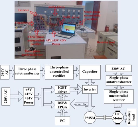
Experiments based on the novel sliding mode observer and the ADRC speed regulator proposed in this paper have been carried out. The experiments structure is as shown in Fig. 5. The experimental object is surface-mounted permanent magnet motor. The PMSM model is SMTP100L1. The parameters are as shown in Table 1.
Table 1Parameters of PMSM
Parameters | Value | Parameters | Value |
Rated voltage (V) | 380 | Inductance (mH) | 12 |
Rated current (A) | 5.1 | Resistance (Ω) | 3.45 |
Rated power (kw) | 2.2 | Pole pairs | 2 |
Rate speed (r/min) | 1500 | Rated flux (Wb) | 0.55 |
Rate torque (N·m) | 14 | Moment of inertia (kg·m2) | 0.0154 |
Fig. 5Block diagram of system
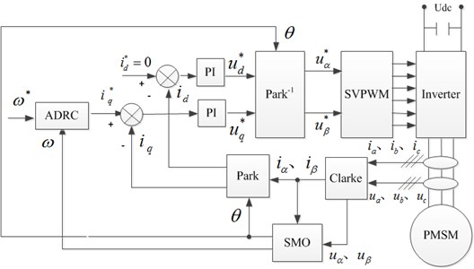
Fig. 6Experimental platform
a) Main circuit and control circuit
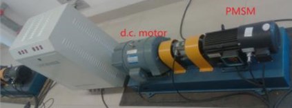
b) PMSM-DC motor unit
In the AC-DC-AC main circuit, AC-DC link is achieved by three-phase autotransformer and uncontrolled rectifier, the intermediate DC link utilizes capacitor to realized filter, DC voltage is adjusted through the automatic coupling voltage regulator. The inverter is composed of 3 IGBT and buffer circuit. DSP2812 and 2SC0108T is utilized in the core control circuit and the driving circuit respectively. The circuit is worked in the half bridge mode as shown in Fig. 6 [21].
In the experimental system, PMSM and DC motor are coaxially connected, with the DC motor power 2.2 KW, separately excitation mode. The DC motor armature winding connected to resistance box. DC motor is used as generator and the load of PMSM, which is shown in Fig. 6(b). The motor is equipped with OMRON incremental photoelectric encoder which is used to measure speed and position as actual values comparing to results of the designed sliding mode observer.
In the experiment, the given speed is 450 r/min, and the incremental photoelectric encoder is used to achieve vector control of the motor by detecting the motor position angle and speed. When the motor is running stably, the signals of position and speed obtained by the designed sliding mode observer instead of the incremental photoelectric encoder are used to control the motor.
Fig. 7Experimental results about real rotor position angle and estimated rotor position angle
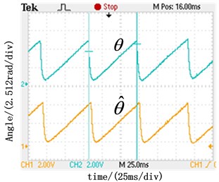
a) Real and estimated angle at the speed of 500 r/min with conventional SMO
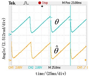
b) Real and estimated angle at the speed of 500 r/min with the novel SMO
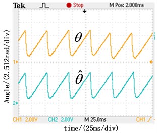
c) Real and estimated angle at the speed of 750 r/min with the novel SMO
The waveforms of estimate and actual rotor position angle at the rotation rate of 500 r/min and 750 r/min are as shown in Fig. 7 respectively. Compared with the results obtained by the conventional sliding model observer shown in Fig. 7(a), the results obtained by the novel SMO shown in Fig. 7(b) have smaller static error. By analyzing the waveforms in Fig. 7(b) and Fig. 7(c) obtained by the novel SMO in different speed, the actual waveform is in line with the estimation , which proves the correctness of the novel SMO.
The waveforms of estimate and actual motor speed obtained by the PI speed regulator and the ADRC speed regulator are as shown in Fig. 8 respectively. The results of the experiments shown SMO can estimate the rotor position and speed accurately, which verifies the correctness and effectiveness of the designed observer. Compared with the PI speed regulator, ADRC speed regulator has better dynamic characteristics in speed overshoot and response speed.
Fig. 8Experimental results about real and estimated rotor speed
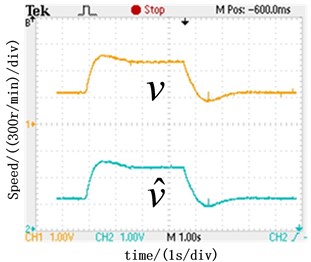
a) Real and estimated rotor speed with PI speed regulator
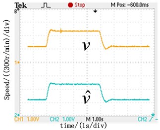
b) Real and estimated rotor speed with ADRC speed regulator
Fig. 9Steady state performance comparison
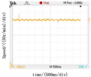
a) Steady state speed with ADRC speed regulator
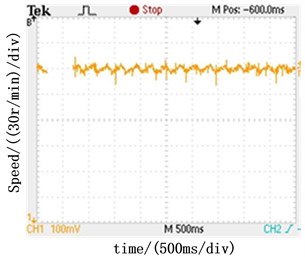
b) Steady state speed with PI speed regulator
The waveforms of maintaining 500 r/min constant speed are shown in Fig. 9. It can be seen that the speed fluctuations of the ADRC speed regulator is in the range of ±3 r/min in Fig. 9(a) and the speed fluctuations of PI speed regulator is in the range of ±7 r/min in Fig. 9(b). It proves that ADRC speed regulator has the better static characteristics.
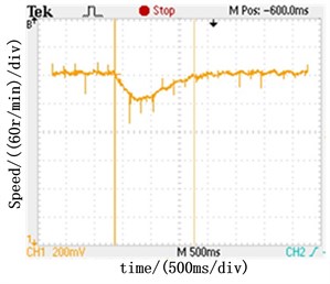
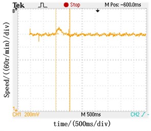
Fig. 10 shows the speed response of PI and ADRC speed regulators under load step. As shown in Fig. 10(a), ADRC speed regulator has the maximum speed dip of 12 r/min and takes 500 ms to reach steady under the positive load step of 5 N∙m. The PI speed regulator has the maximum speed dip of 40 r/min and takes 1.2 s (shown in Fig. 10(b)). The waveforms in Fig. 10(c) and Fig. 10(d) are under the condition of negative load step of 5 N∙m. The results prove that the ADRC speed regulator has better anti-disturbance performance than the PI speed regulator.
The numerical analysis of the experimental results are as shown in Table. 2
Table 2Experimental results (N presents novel control system, C presents conventional control system)
Items of the comparison | N | C |
Static error of position angle (°) | 5 | 27 |
Dynamic response overshoot (r/min) | 19 | 45 |
Dynamic response time (s) | 0.6 | 1.5 |
Velocity static error (r/min) | ± 3 | ± 7 |
Speed dip under positive load step (r/min) | –18 | –55 |
Response time under positive load step (s) | 0.5 | 1.5 |
Overshoot under negative load step (r/min) | 24 | 65 |
Response time under negative load step (s) | 0.5 | 1.5 |
Simulation studies are performed to investigate the ability of the controller to operate in the presence of external noise: such as load step etc. The simulation results and experimental results are consistent. The simulation results show that the ADRC controller can estimate the load disturbance and mutation. The controller has a good robustness to load because that the load disturbance and mutation are compensated. Simulation results are shown in Fig. 11.
Fig. 10Speed response under load step
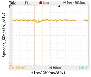
a) Speed response under positive load step with ADRC speed regulator
b) Speed response under positive load step with PI speed regulator
c) Speed response under negative load step with ADRC speed regulator
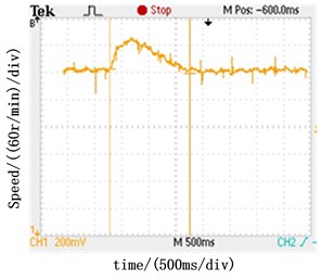
d) Speed response under negative load step with PI speed regulator
Fig. 11Simulation results for ADRC and PI regulator
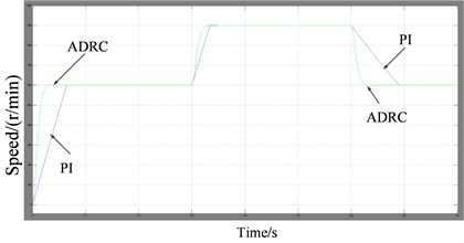
a) Speed response under negative and positive speed step
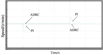
b) Speed response under negative and positive load step
6. Conclusion
A novel SMO and ADRC speed regulator of PMSM are presented in the paper. Compared to conventional SMOs, the proposed SMO uses sigmoid function to weaken chattering problem; utilizes Kalman filter to acquire back EMF. Phase compensation can be omitted and the identification error is smaller when calculating the rotor position angle; uses Phase-locked loop to achieve rapidly identify of speed response characteristics and improvement of rotor speed estimation precision. The ADRC speed regulator is designed to substitute for conventional PI speed regulator, which achieves better response rates, small overshoot and better control effect.
References
-
Wang Weihua, Xiao Xi, Ding Youshuang An improved predictive current control method for permanent magnet synchronous motors. Transactions of China Electrotechnical Society, Vol. 28, Issue 3, 2013, p. 50-55.
-
Qiu Xin, Huang Wenxin, Yang Jianfei, Bu Feifei A direct torque control strategy based on torque angle for permanent magnet synchronous motors. Transactions of China Electrotechnical Society, Vol. 28, Issue 3, 2013, p. 56-62.
-
Li Hongmei, Chen Tao, Yao Hongyang Mechanism, diagnosis and development of demagnetization fault for PMSM in electric vehicle. Transactions of China Electrotechnical Society, Vol. 28, Issue 8, 2013, p. 276-284.
-
Kang Jinsong, Zeng Xiangyun, Wu Ying Study of position sensorless control of PMSM based on MRAS. IEEE International Conference on Industrial Technology, 2009, p. 1-4.
-
Gu ShanMao, He Fengyou, Zhang Hui Study on extend Kalman filter at low speed in sensorless PMSM drives. International Conference on Electronic Computer Technology, 2009, p. 311-316.
-
Srikanth V., Dutt A. A. A comparative study on the effect of switching functions in SMO for PMSM drives. IEEE International Conference, 2012, p. 1-6.
-
Ying Shieh Kung, Nguyen Vu Quynh, Chung Chun Huang, Liang Chiao Huang Design and simulation of adaptive speed control for SMO-based sensorless PMSM drive. Intelligent and Advanced Systems, 2012, p. 439-444.
-
Dong Jiang, Zhengming Zhao, Fei Wang A sliding mode observer for PMSM speed and rotor position considering saliency. Power Electronics Specialists Conference, 2008, p. 809-814.
-
Changsheng Li, Elbuluk M. A sliding mode observer for sensorless control of permanent magnet synchronous motors. 36th IAS Annual Meeting, Vol. 2, 2001, p. 1273-1278.
-
Lascu C., Reescu G. D. Sliding-mode observer and improved integrator with dc-offset compensation for flux estimation in sensorless controlled induction motors. IEEE Transactions on Industrial Electronics, Vol. 53, Issue 3, 2006, p. 785-794.
-
Foo G., Rahman M. F. Sensorless sliding-mode MTPA control of an IPM synchronous motor drive using a sliding-mode observer and HF signal injection. IEEE Transactions on Industrial Electronics, Vol. 57, Issue 4, 2010, p. 1270-1278.
-
Feng Y., Zheng J., Yu X., Truong N. Hybrid terminal sliding-mode observer design method for a permanent-magnet synchronous motor control system. IEEE Transactions on Industrial Electronics, Vol. 56, Issue 9, 2009, p. 3424-3431.
-
Kim Hongryel, Son Jubum, Lee Jangmyung A high-speed sliding-mode observer for the sensorless speed control of a PMSM. IEEE Transactions on Industrial Electronics, Vol. 58, Issue 3, 2011, p. 4069-4077.
-
Sun Kai, Xu Zhenlin, Zou Jiyong A novel approach to position sensorless vector control of PMSM based on active-disturbance rejection controller. Proceedings of the CSEE, 2007, p. 18-22.
-
Xia Changliang, Li Zhengjun, Yang Rong Control system of brushless DC motor based on active-disturbance rejection controller. Proceedings of the CSEE, 2005, p. 82-86.
-
Han Jingqing Nonlinear state error feedback control law-NLSEF. Control and Decision, Vol. 10, Issue 3, 1995, p. 221-225.
-
Han Jingqing From PID technique to active disturbance rejection control technique. Control Engineering of China, Vol. 9, Issue 3, 2002, p. 13-18.
-
Pan Yuedou, Xu Jie, Chen Hu, Gao Ruiliang Stability analysis and application of ESO in direct torque control of matrix converter. Control and Decision, Vol. 28, Issue 4, 2013, p. 585-561.
-
Branicky Michael S. Multiple Lyapunov functions and other analysis tools for switched and hybrid systems. IEEE Transactions on Automatic Control, Vol. 43, Issue 4, 1998, p. 475-482.
-
Wang Y. H., Yao Y., Ma K. M. Error estimation of second order extended state observer. Journal of Jilin University: Engineering and Technology Edition, Vol. 40, Issue 1, 2010, p. 143-147.
-
Qiu Zhongcai, Wang Bin, Guo Jiling, Xiao Jian A sliding mode observer with Kalman filter for PMSM speed and position. Power Electronics, Vol. 47, Issue 11, 2013, p. 103-105.
About this article
This work was supported by National Science Foundation of China (51177137); supported by the Fundamental Research Funds for the Central University (SWJTU12BR015).
