Abstract
This paper proposed an improved virtual reference model for semi-active suspension to coordinate the ride comfort and handling stability of a vehicle. The reference model combines the virtues of sky-hook and ground-hook control logic, and the hybrid coefficient is tuned according to the longitudinal and lateral acceleration so as to improve the handling stability especially in high speed condition. The full scale vehicle model considering the heave-pitch-roll motion is presented, and the theory of hydro-pneumatic suspension with continuous adjustable damper is also illustrated. A sliding mode controller is designed to track the states of the reference model. The stability of the sliding mode control strategy is analyzed by means of Lyapunov function approach taking into account of the nonlinear damper characteristics and sprung mass variation of the vehicle. Finally, the performances of the controller are validated under three typical working conditions: the random road, speed bump road and sharp acceleration and braking. The simulation results indicated that, compared with the traditional passive suspension, the proposed control algorithm can offer a good coordination between ride comfort and handling stability of a vehicle. The designed controller could be commercially implemented in semi-active suspension systems.
1. Introduction
Classic conventional suspension systems consist of springs, shock absorbers and a set of mechanical elements which links the suspended body to wheels and allows relative motion between the two. The performance of vehicle suspension system is typically rated by its ability to provide the improvement of ride comfort and handling stability under different road excitations. The traditional passive suspension systems are known to have the limitations in coordination between the vibrations isolation and vehicle body control of a vehicle. With the rapid development of mechatronics and control theory, controllable suspension is a good alternative to resolve the inherent coordination among the performances of suspension systems. Active suspensions can provide a good ride comfort and constrain the pitch and roll motion in transient and steady state by exerting the forces from the actuators. But the complexity, high expense and considerable power requirements of active suspension systems limit its development and applications in commercial automobile industry. Semi-active suspension requires less power and can provide the most favorable compromise between costs and performances. Another feature of semi-active suspension systems is its fail-safe compared with the active suspension systems. Once the control system fails, it can also act as a traditional passive suspension system. And it is expected to play an important role in the future and has raised increasing attentions in recent decades [1, 2].
Hydro-pneumatic suspension was invented by Citroen in 1950s, and it is widely used by automobile manufacturers due to its larger forces with compact size, such as trucks [3], military vehicles [4] and some commercial vehicles [5], et al. Even though this system is currently utilized only in a small number of vehicles due to high development efforts and the additional costs of the suspension components, it is highly promising and attractive. It can offer superior ride quality even when quickly traversing poorly surfaced roads. A nitrogen reservoir with variable volume yields a spring force with nonlinear force-deflection characteristics. And these features of hydro-pneumatic will be further explained in the following section.
The key factor of semi-active suspension is in algorithms. A wide range of modern control theories have been applied in the control of automotive suspension systems [6, 7]. The sky-hook control strategy was introduced by Karnopp et al. as classical control logic for active suspension systems [8]. This control logic is simple and robust to the variation of vehicle payload and different road excitations. But the ideal sky-hook control law only dissipates the vibration energy of vehicle body, and the vibration of unsprung mass will be deteriorated. It cannot coordinate vehicle ride quality and road holding. Conversely, the ground-hook control logic is aim to improve the road holding and handling stability of a vehicle, but deteriorates the ride comfort. Even though neither of the two ideal controllers truly happens, we can still use these logics as control reference model. Hybrid model is combined with the sky-hook and ground-hook as reference for the sliding mode control, in Ref. [9], road disturbance is as input for the reference model. There are two typical methods to obtain the road information in the preview control of suspension systems. The first is preview control based on look-ahead (such as 3D camera) to obtain the road surface information; the second is preview control based the front wheel vibration signals to adjust the characteristics of rear suspension. But in practice, the road disturbance information is difficult to be measured due to the high cost or limitations of technology. Some intelligent approaches are also applied in suspension control since the nonlinear and uncertainty characteristics existing in vehicle suspension systems, such as neural networks [10] and genetic algorithms [11, 12]. The mathematical proof for stability of the intelligent controller is not demonstrated yet; and the system stability is important especially for the active suspension systems.
Sliding mode methodology is a powerful technique in either estimating states or controlling of a given system; it has been widely used in suspension systems [13, 14]. SMC is a nonlinear variable structure control method by application of a discontinuous signal that forces the system to slide along the restricted sliding mode surface. Chen et al. proposed a SMC for semi-active suspension [15], and this is an all-state feedback control. But some of the state information is difficult to be measured or estimated, such as tire deflections or road disturbances. Ref. [16] designed a hybrid control algorithm for semi-active suspension by using the constant hybrid coefficient; the results indicate that hybrid control can offer benefits to both the sprung mass and the unsprung mass. Yao [17] et al. used sliding mode strategy to control a semi-active magnetic-rheological suspension and validated the effectiveness of this control method via hardware-in -loop simulation. Morteza et al. [18] studied the control of an electro-hydraulic active suspension based on a combination of PID and sliding mode control, taking into account the actuator faults and hydraulic actuator time delay. Although good performances are achieved by these strategies, some intrinsic problems remain to be solved, such as the limitations in constraining of the pitch and lean motion of vehicle body as well as the vertical vibration.
A SMC based on hydro-pneumatic suspension is proposed for semi-active suspension in this paper. In order to achieve a good coordination between vehicle ride comfort and handling stability, a hybrid reference model is applied in the control algorithm. The hybrid coefficient is adjusted by the designed tuning logic according to the longitudinal and lateral acceleration so as to constrain the body lean to one side or pitch forward when sharp cornering and braking. The control performance is validated in Matlab/Simulink environment under three typical working conditions.
The remainder of this paper is organized as follows: the dynamic model of full-scale vehicle and the hydro-pneumatic suspension model are established respectively in Section 2; the virtual hybrid reference model is presented in Section 3; the SMC algorithm is illustrated in Section 4; simulation results and discussion are given in Section 5; at the end of the paper, the conclusions and future work are given.
2. Full-vehicle dynamic model
The linear model can replace the nonlinear one around the operation conditions, out of this level, the linear model is not valid, and a linear representation of the system dynamics is not sufficient [19]. So a full scale nonlinear vehicle model considering the heave-pitch-roll motion is necessary in development of vehicle technologies, i.e. suspension control, chassis design, active safety, driving assistance system, etc.
The full vehicle is illustrated in Fig. 1. Heave, pitch, and roll motions of vehicle body are considered in the modelling of the vehicle dynamics. The full vehicle model consists of the chassis (sprung mass) and wheels (unspung mass). The sprung mass is including passenger, internal components and it may vary according to the passenger number and the payload condition of a car. It connects by the suspension systems to four wheels (unsprung masses). The four wheels are free to bounce vertically relative to the vehicle body. The dynamics of the hydro-pneumatic are taken into consideration in this study. The damping forces are adjusted by controlling the current of proportional relief valve according to a designed logic. Unsprung mass is denoted as , which is supported by the tire modeled as liner spring with stiffness coefficient . The displacement of sprung mass and unsprung mass are denoted as and respectively; and the road excitation is .
Fig. 1Full vehicle model with semi-active suspension systems
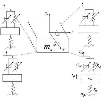
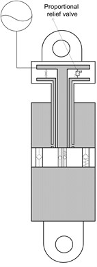
Fig. 2Structure of hydro-pneumatic suspension
The vehicle dynamic equations of the vertical, pitch and roll motions are expressed as:
where, is the suspension force generated from hydro-pneumatic suspension, which consists of the spring force and damping force, it can be described as:
where, is the control current of damping force.
The dynamics equations of wheels’ vertical motion are given as follows:
Assuming that the pitch angle and roll angle are small, so the suspension deflections can be deduced:
The diagram of hydro-pneumatic suspension is shown in Fig. 2. It composes of an accumulator and cylinder. The accumulator has a pre-charge gas pressure, and it works as a spring in a vibration system. The spring force can be described as:
where, is initial pressure of accumulator; is initial volume of accumulator; is the suspension leverage ratio, the details can be referenced in Appendix.
The damping force can be continuously adjusted from soft to hard according to a designed control algorithm. Based on the by-pass principle, semi-active dampers use a proportional relief valve (electrically operated) in parallel with a conventional damper orifice and valve assembly. If the bypass valve is closed, all the flow goes through the conventional damper orifice and valve, and it will be hard damping. If the bypass valve is open, most of the flow passes through the bypass valve due to the lower flow resistance, and the damping characteristic will be soft.
Fig. 3Damping current-velocity-force fitting comparison (the dotted line is original test data; the continuous line is the fitting result. When Δz˙s< 0, the suspension is in rebound motion)
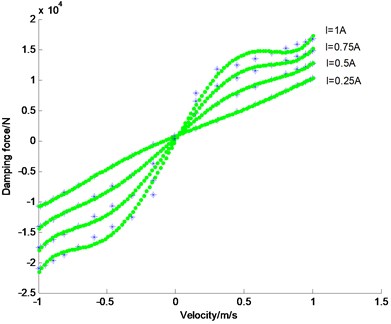
In this study, we use the high order polynomial function to describe the nonlinear characteristics of the hydro-pneumatic damping force. The comparison of fitting curve and experiment data are plotted in Fig. 3. And this model is easy to calculate the control current according to a desired damping force. The damping force is a function of the current input and the suspension relative velocity as follows:
where, , and are the fitting coefficients obtained from the experimental data.
When the suspension relative velocity is obtained and the desired damping force is determined according the control law, the control current can be obtained by:
This is a quadratic equation, and we learned that , so there are two roots for this equation, one is positive, the another one is negative. And we choose the positive one as the control current.
3. Virtual reference model description
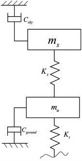
The ideal sky-hook and ground-hook are that the vehicle body connects the imaginary line with the damper. The sky-hook control policy is ride comfort-oriented; while, the ground-hook is road holding-oriented. In order to improve the ride comfort and handling stability of the vehicle, a hybrid reference model is proposed. The quarter-car hybrid reference model is shown in Fig. 4.
Fig. 4The configuration of hybrid reference model
The on-off sky-hook control logic can be expressed as:
where, is sky-hook reference damping coefficient.
The on-off ground-hook control logic can be expressed as:
where, is ground-hook reference damping coefficient:
where, is hybrid damping force; is the hybrid coefficient.
Deeps and bumps cause the wheels to move up and down. Cornering, braking and acceleration can make the body lean to one side or pitch forward. And most of the time, this will deteriorate the vehicle handling and stability, even safety. So we use the hybrid coefficient to adjust the hybrid degree between sky-hook and ground-hook. Consider the following case, when , the control policy degrades into pure skyhook and this is focused on the ride comfort. When , the control is purely ground-hook and this is focused on handling stability. Here the hybrid coefficient is calculated by the longitudinal and lateral acceleration:
where, and is the normalized longitudinal acceleration and lateral acceleration, respectively.
4. Control system design
SMC is a highly robust technique in controlling of systems with bounded uncertainty. And it uses discontinuous control signal to drive a state-trajectory towards a sliding surface and maintain it on this surface for all control time.
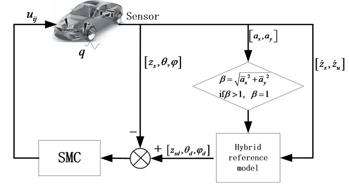
The control diagram of SMC is shown in Fig. 5. The sprung mass velocity and unsprung mass velocity are measured by the equipped sensors in the vehicle as input for the hybrid reference model. In the control algorithm application, we use the measured vibration information of suspension system, so as to avoid measuring the road disturbance information. Because the road disturbance is difficult to obtain in practice.
Fig. 5The diagram of control algorithm
The system functions Eqs. (1)-(3) can be rewritten as follows:
where, denoted the reciprocal of inertial parameters, , , .
Define the tracking error as:
where, are the desired sprung mass velocity, pitch rate and roll rate, respectively, from the hybrid reference model.
Choose the sliding surface as:
where, is the sliding surface for the control; is the positive constant vector.
The derivation along surface incorporation of system perturbation is:
where, ; ; .
So the equivalent control law can be deduced in absence of the system perturbation:
Considering the system uncertainties and perturbation, sliding mode control including the equivalent control and switching control law is presented:
here, is the sliding mode term representing the nonlinear state feedback control for constraining the perturbation of the system parameters and it will be designed later.
Design the Lypunov function of the system as following:
A sufficient condition for the stability of a sliding mode controller is that the Lypunov function should subject to Eq. (25) in a neighborhood of the sliding surface:
Substituting Eq. (22) into (25), we obtain:
Here, we assume that, the system uncertainty boundary as , , , , , . So design the nonlinear sliding mode control law as:
Substituting Eq. (27) into (25), we obtain:
where, is the Euclidean norm.
When choose , , , we have:
In order to eliminate the chattering during the switch control of SMC, an improved control law is proposed [20]:
where, is a small positive constant:
where, is the pseudo-inverse of matrix . The solutions of Eq. (34) can be considered as optimal results for the semi-active suspension system. And the control current can be calculated according to Eq. (9).
5. Simulation and discussion
CarSim is commercially available software and widely used to simulate and analyze the dynamic behavior of wheeled vehicles. It is employed in conjunction with Matlab/Simulink to simulate the effects of control algorithms on a full-vehicle model. In order to demonstrate the effectiveness of the proposed semi-active suspension control algorithm, it was implemented in the Matlab/Simulink environment and co-simulated with the Carsim software. Full vehicle in Carsim is considered as a real car which provides the control inputs and measurement outputs. And the control algorithm is designed in Matlab/Simulink. The control performances are validated under three typical working conditions (random road, speed bump road and sharp acceleration and braking). The smooth random road represents consistent excitations with wide range of frequencies; the speed bump road represents the discrete events of relatively short duration and high intensity; and sharp acceleration and braking can make a large pitch forward of vehicle body. The vehicle parameters are listed in Table 1.
Table 1Parameters of off-road vehicle suspension
Description | Symbol | Value |
Sprung mass | 9000 kg | |
Unsprung mass | 250 kg | |
The distance of body mass center to front axis | 1.94 m | |
The distance of body mass center to rear axis | 2.56 m | |
Tire stiffness | 1501200 N/m | |
Roll moment of inertia | 3531 kg·m2 | |
Pitch moment of inertia | 16243 kg·m2 | |
Track width | 1.920 m | |
Leverage ratio | 1.507 | |
Initial pressure of accumulator | 8 MPa |
5.1. Case 1 random road excitation
The random road are classified as a series of standards according to the road power spectral density (PSD) values. The PSD of random road excitation is:
where, is the space frequency (m-1), is the reference space frequency, 0.01 m-1; is the road roughness coefficient, here, 256×10-6; is frequency index, it reflects the frequency structure of the pavement, usually 2.
Ref. [21] proposed random road model by integrating Gaussian white noise. And the first derivative of road excitation can be described as:
where, is the Gauss white noise; is the low cut-off space frequency, 0.001 m-1; is the vehicle speed.
The model of four wheels road excitation can be referenced from Ref. [22]. The four wheels of irregular road profiles are plotted in Fig. 6. The vehicle speed is kept constant as 60 km/h. And the simulation results are shown in Fig. 7-Fig. 11.
Fig. 6Time history of road input
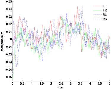
Fig. 7The PSD comparison of vertical acceleration
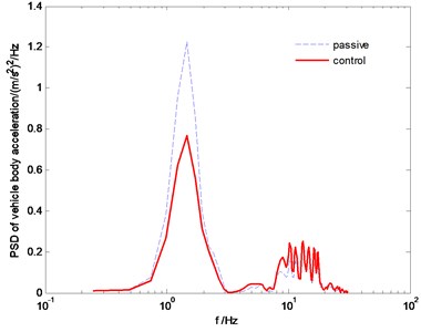
Fig. 8The PSD comparison of suspension stroke
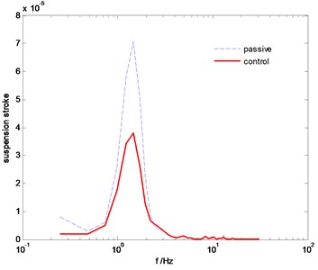
Fig. 9The PSD comparison of tire dynamic load
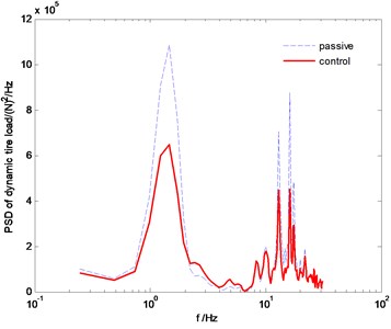
Fig. 10Time history of roll angle
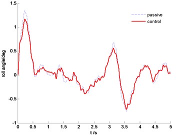
Fig. 11Time history of pitch angle
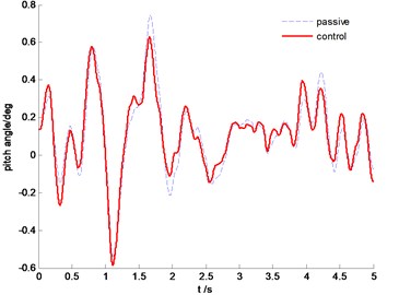
The power spectral density (PSD) comparisons of vehicle body vertical acceleration, suspension stroke and the tire dynamic load are plotted in Fig. 7-Fig. 9, respectively. We can find that the proposed SMC control can constrain the vehicle body acceleration and wheel dynamic load at the same time, achieve a better coordination between the ride comfort and handling stability. Fig. 10 and Fig. 11 are the comparison of pitch and roll angle. It can be concluded that the proposed SMC control algorithm can provide a good ride comfort and constrain vehicle pitch and roll motion under the random road condition.
5.2. Case 2 speed bump road excitation
Time history of speed bump road is plotted in Fig. 12, and the vehicle velocity is kept constant as 30 km/h.
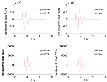
Fig. 13-Fig. 16 are the simulation results comparison between SMC and tradional passive suspension. We can find that, at the beginning when the front wheels hit the bump, the response of the controllable suspension is similar to the passive suspension, but after that, the controllable suspension can attenuate the resonant quickly compared with the traditional passive suspension. This will be benefit for improving the ride comfort and handling stability.
Fig. 12Time history of speed bump road input
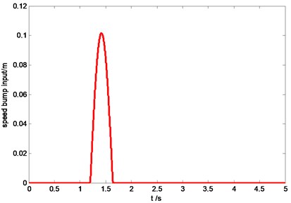
Fig. 13Time history of vehicle body vertical acceleration
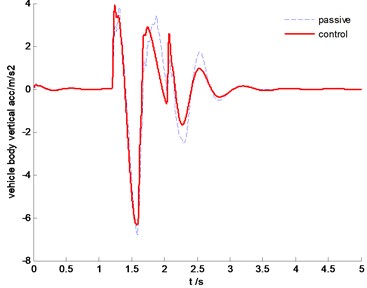
Fig. 14Time history of suspension strokes
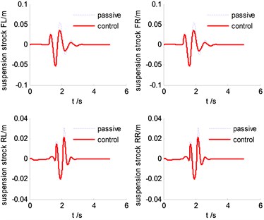
Fig. 15The diagram of dynamic tire forces
5.3. Case 3 sharp acceleration and braking
In this section, sharp acceleration and braking is carried out to validate the SMC control performance. The vehicle is accelerated from 0 km/h during first 10 s to 85 km/h, and kept at this speed for 5 s, and then decelerated to 0 km/h, the time history of longitudinal acceleration is shown in Fig. 17.
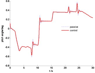
The vehicle body comparison of vertical acceleration is plotted in Fig. 18. It is clearly indicated that the SMC control can constrain vertical resonance of vehicle body and improve driving comfort significantly. From Fig. 19, we can find that the proposed control algorithm can reduce the pitch angle, but the effectiveness is limited due to the large inertial force in this situation.
Fig. 16Time history of pitch angle
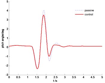
Fig. 17Time history of longitudinal acceleration (including acceleration and braking)
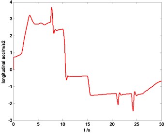
Fig. 18Time history of vertical acceleration of vehicle body
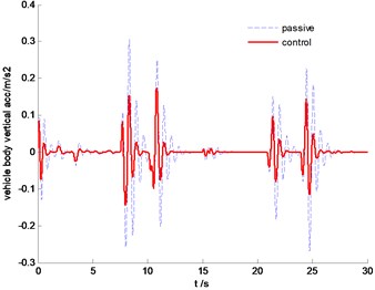
Fig. 19Time history of pitch angle
6. Conclusions
This paper proposes a SMC algorithm for semi-active suspension system. In order to achieve a good coordination between the ride comfort and handling stability, a hybrid reference model which combines virtues of sky-hook with ground-hook control logics is presented. The following conclusions can be drawn,
1) The proposed SMC algorithm avoids using the road disturbance information; this will improve the robustness to unknown roads and vehicle parameters variation.
2) The algorithm of hybrid coefficient is proposed based on the longitudinal and lateral acceleration information. This will regulate the reference model to tend to sky-hook or ground-hook according to vehicle real-time condition.
The control performances are validated in Matlab/Simulink environment under three different working conditions. For further studies, the real road test should be implemented in the future work.
References
-
Chiang H., Lee L. Optimized virtual model reference control for ride and handling performance-oriented semi-active suspension systems. IEEE Transactions on Vehicular Technology, Vol. 64, Issue 5, 2014, p. 1679-1690.
-
Xiao L., Zhu Y. Sliding-mode output feedback control for active suspension with nonlinear actuator dynamics. Journal of Vibration and Control, 2013, p. 1-18.
-
Van der Westhuizen, Francois S., Els P. Schalk Comparison of different gas models to calculate the spring force of a hydropneumatic suspension. Journal of Terramechanics, Vol. 57, Issue 2, 2015, p. 41-59.
-
Kinagi Ganesh Vijaykumar, Syam Prasad Pitchuka, et al. Hydropneumatic suspension design for light military tracked vehicle. SAE Technical Paper, No. 2012-01-1911, 2012.
-
Becker M., Jaker K. P., Fruhauf F., et al. Development of an active suspension system for a Mercedes-Benz Coach (O404). Proceedings of the 1996 IEEE International Symposium on Computer-Aided Control System Design, 1996, p. 146-151.
-
Cao J., Liu H., Li P., et al. State of the art in vehicle active suspension adaptive control systems based on intelligent methodologies. IEEE Transactions on Intelligent Transportation Systems, Vol. 9, Issue 3, 2008, p. 392-405.
-
Cao D., Song X., Ahmadian M. Editors’ perspectives: road vehicle suspension design, dynamics, and control. Vehicle System Dynamics, Vol. 49, Issue 1-2, 2011, p. 3-28.
-
Karnopp D., Crosby M. J., Harwood R. A. Vibration control using semi-active force generators. Journal of Manufacturing Science and Engineering, Vol. 96, Issue 2, 1974, p. 619-626.
-
Assadsangabi B., Eghtesad M., Daneshmand F., et al. Hybrid sliding mode control of semi-active suspension systems. Smart Materials and Structures, Vol. 18, Issue 12, 2009, p. 1-10.
-
Guo D. L., Hu H. Y., Yi J. Q. Neural network control for a semi-active vehicle suspension with a magnetorheological damper. Journal of Vibration and Control, Vol. 10, Issue 3, 2004, p. 461-471.
-
Sun L., Cai X., Yang J. Genetic algorithm-based optimum vehicle suspension design using minimum dynamic pavement load as a design criterion. Journal of Sound and Vibration, Vol. 301, Issue 1, 2007, p. 18-27.
-
Dong X. M., Yu M. Genetic algorithm based fuzzy logic control for a magneto-rheological suspension. Journal of Vibration and Control, Vol. 20, Issue 9, 2014, p. 1343-1355.
-
Deshpande V. S., Mohan B., Shendge P. D., et al. Disturbance observer based sliding mode control of active suspension systems. Journal of Sound and Vibration, Vol. 333, Issue 11, 2014, p. 2281-2296.
-
Balamurugan L., Jancirani J., Eltantawie M. A. Generalized magnetorheological (MR) damper model and its application in semi-active control of vehicle suspension system. International Journal of Automotive Technology, Vol. 15, Issue 3, 2014, p. 419-427.
-
Chen B. C., Shiu Y. H., Hsieh F. C. Sliding-mode control for semi-active suspension with actuator dynamics. Vehicle System Dynamics, Vol. 49, Issue 1-2, 2011, p. 277-290.
-
Goncalves F. D., Ahmadian M. A hybrid control policy for semi-active vehicle suspensions. Shock and Vibration, Vol. 10, Issue 1, 2003, p. 59-69.
-
Yao J. L., Shi W. K., Zheng J. Q., et al. Development of a sliding mode controller for semi-active vehicle suspensions. Journal of Vibration and Control, 2012, p. 1-9.
-
Moradi M., Fekih A. Adaptive PID-sliding-mode fault-tolerant control approach for vehicle suspension systems subject to actuator faults. IEEE Transactions on Vehicular Technology, Vol. 63, Issue 3, 2014, p. 1041-1054.
-
Chamseddine Abbas, Hassan Noura Control and sensor fault tolerance of vehicle active suspension. IEEE Transactions on Control Systems Technology, Vol. 16, Issue 3, 2008, p. 416-433.
-
Lee H., Utkin V. I. Chattering suppression methods in sliding mode control systems. Annual Reviews in Control, Vol. 31, Issue 2, 2007, p. 179-188.
-
Wu Z. C., Chen S. Z., Yang L., Zhang B. Model of road roughness in time domain based on rational function. Transaction of Beijing Institute of Technology, Vol. 29, Issue 9, 2009, p. 795-798.
-
Hongbin R., Sizhong C., Zhicheng W. Model of excitation of random road profile in time domain for a vehicle with four wheels. International Conference on Mechatronic Science, Electric Engineering and Computer, China, 2011, p. 2332-2335.
About this article
This work is supported by the National Nature Science Foundation of China (Grant No. 51375046 and Grant No. 51205021).
