Abstract
The paper presents the design of a planetary drive with 2 degrees of freedom and simulation of the proposed mechanism in ADAMS software. The mechanism can be used to smoothly change the reduction ratio depending to the applied load on the output shaft. At constant input of motor the proposed mechanism is able to provide variable output speed. The paper is aimed to study the capability of the mechanism to adapt the operation to variable loads. The design constraint has been selected to an application as a reducer of speed on a wind mill. The results of the simulation have been aimed to outline the output parameters of a planetary drive for wind mills.
1. Introduction
Planetary drive are mainly used in different applications in industry such as for differential drive of automobiles, final drives of tractors, shipping, wind turbines, aerospace and many others. A gearbox is a mechanical device utilized to increase the output torque or change the speed of a motor, [IFToMM Terminology, 2003]. The efficiency of gear trains depends on many factors such as the type and number of gears, the number and type of bearings and friction elements used to transfer power from a power source to specific outputs. Factors to improve the efficiency of gearboxes have been studied with recent approaches in [1-3]. Design and optimization of cylindrical gear drives based on ISO 6336 has been pointed out in [4]. Planetary drives are mainly used in some applications where a large range of speed reduction is required as presented in [5, 6]. Some planetary gear drive design solutions have been proposed in the literature, as pointed out, for example in [7-9]. Several design characteristics have been selected for applications of the planetary drive, like for example, in wind turbines. Wind mills can be identified by regarding to a wind mill of 8-12 kW power and with average speed of wind of 15-30 m/s.
2. A Kinematics of a new planetary drive
Generally a planetary gearbox contains one rigid body that rotates around its own axis and then rotates around another axis. The points of the rigid body will describe epicycloid trajectory. A planetary gearbox can be achieved by mounting the rigid body which is referred to a planet [10], on a carrier, Fig.1. Many new planetary gear box solutions have been proposed in the literature, for example in [11-13].
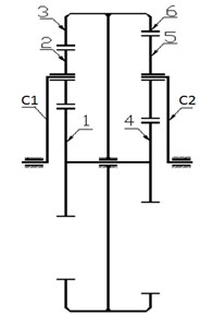
The paper presents the planetary mechanism consisting of a planetary gear set. The proposed mechanism has two degrees of freedom with two mobile planetary gear sets. The design of the proposed mechanism is asymmetrical, Fig. 2. The mechanism has some features such as smoothly changing the reduction ratio. The reduction ratio changes automatically depending on the applied load of output shaft. The paper describes simulation of a new solution for improving the efficiency of planetary gear mechanism.
Fig. 1H-carrier. A general design of planetary gear mechanism: 1 – sun gear; 2 – ring gear; 3 – carrier; 4 –satellite.
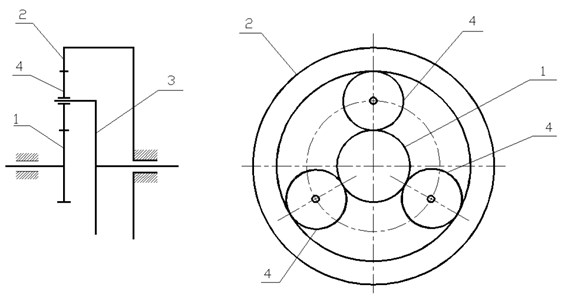
Fig. 2A kinematic scheme: C1 – input carrier, 1 – input sun gear, 2 – input planet gear, 3 – input internal ring gear, 4 –output sun gear, 5 –output planet gear, 6 – output internal ring gear, C2–output carrier
A characterization of the proposed mechanism in Fig. 2 can be expressed as a function of following parameters of torques , on the input and output carriers and constant input speed of motor . The kinematic relations among the speeds of the wheels with 1, 2, 3, 4, 5, 6 is expressed in the forms:
where:
where is number of teeth of gears 1, 2, 3, 4, 5, 6).
From Eq. (1) and (2) the speeds , of wheels 3 and 1 is obtained as:
Input and output powers is expressed as:
The efficiency of the planetary drive is expressed in form:
3. ADAMS virtual model
The virtual CAD design of the proposed planetary drive with two degrees of freedom has been created within Solid Works software the exported ADAMS software. In order to simulate in ADAMS the following main parameters such as an input constant speed of motor and output torque have been specified. The input constant velocity of motor of 400 rpm was applied to the input carrier. External torque with a constant value of 45 Nm was applied to the output shaft of planetary drive. The proposed model of planetary drive is demonstrated in Fig. 3. A zoomed view of the gears is demonstrated in Fig. 4. The number of teeth of gears are listed in Table 1.
Fig. 3The virtual model of the proposed design solution with reference frames and applied loads
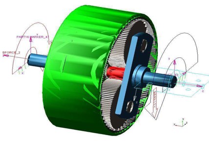
Fig. 4A zoomed view for the gearing system in Fig. 3: z1 – input sun gear; z2 – input planet gear; z3 –input internal ring gear; z4 – output sun gear; z5 – output planet gear; z6 – output internal ring gear
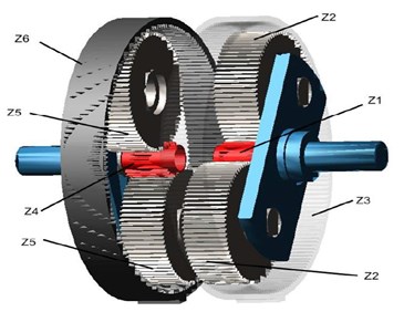
Table 1Number of teeth for gears in Fig. 4
Gear | Number of teeth |
Input sun gear, | 60 |
Input satellite, | 20 |
Input ring gear, | 100 |
Output sun gear, | 12 |
Output satellite, | 44 |
Output ring gear, | 100 |
Module | 1.0 |
4. Simulation of the virtual model
Input angular speed of motor and torque are given as a constant values of motor of 400 rpm and 15 Nm. Output torque can be variable from 1 up to 8 Nm. The friction coefficient of gears was set as equal to 0.2. Table 2 shows main other parameters that were assumed and considering material, force exponent and penetration depth.
During the simulation of proposed model the output parameters such as torque, contact forces, angular speed were computed in order to investigate the dynamic behavior of the proposed mechanism. By applying a variable torque to the output carrier of mechanism the input carrier rotates continuously with constant velocity of 400 rpm, than means the mechanism works with 2 DOFs and reduction ratio changes automatically. During the simulation the contact forces have also been computed. Schemes of contact forces between gears are presented in Fig. 5 and Fig. 6.
Fig. 5The contact forces between gears: 1 and 2 contact forces between gears of an input link
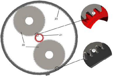
Fig. 6The contact forces between gears: 3 and 4 contact forces between gears of an output link
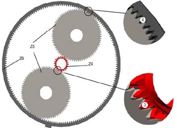
Table 2The simulation parameters of model in Fig. 3
Parameter | Value | Unit |
Input speed | 400 | Rpm |
Input torque | 15 | Nm |
Output speed | Plots in Fig. 3 | Rpm |
Output torque | Variable (1-8) | Nm |
Density | 7.802 E-006 | Kg/mm3 |
5. Simulation results
During the simulation of the mechanism a variable torque was applied in order to check the feasibility of change reduction ratio. The proposed planetary drive can adapt to external applied variable load to the output carrier by smoothly changing reduction ratio of mechanism. Dynamic simulations are carried out with the aim to check the feasibility of the proposed mechanism for wind mills. The obtained simulation results shown in the plots of Figs. 7 to 17.
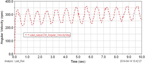
Speeds of the input and output shafts of planetary drive are shown in Fig. 7. The input angular speed is given as a speed of motor with value of 400 rpm, Fig. 7. The angular speed of the output carrier with average value of 420 rpm is shown in Fig. 7. As can be observed in the plot in Fig. 7 the output angular velocity changes from 400 up to 450 rpm during all the test and it can be explained the variable torque was applied to the output carrier of mechanism. Fig. 8 shows the plot of computed speed of the internal ring gears. The internal ring gears rotate with the approximately speed of 395 rpm. In Fig. 8 the angular speeds of input and output internal gears are shown. The generated variable output torque by ADAMS also affected to the angular speeds of these gears. Fig. 9 shows the plot of torque of the internal ring gears. The torque changes from 6 up to 8.6 Nm. The torque change appears as a cyclic and small peaks are appeared, which can be happened due to the fast variation of loads.
Fig. 7The plot of the angular speeds of input and output carrier
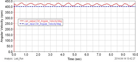
Fig. 8The plot of the angular speed of the internal ring gears
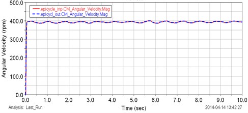
Fig. 9The plot of the torque of the internal ring gears
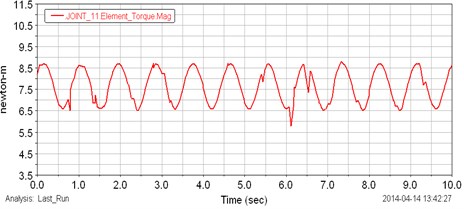
Fig. 10 shows the plot of computed angular speeds of the input and output sun gears. The input and output sun gears have same rotation due to rigidly fixing in same shaft. Results show that the speeds of sun gears can change from 450 up to 500 rpm during all test. Fig. 11 presents the computed torque of the sun gears. The torque can change from 1 up to 4 Nm with cyclic curve. Fig. 12 shows the Computed plot of the speed of the input planet gears. Approximately speed of input planet gears is 375 rpm. Fig. 13 shows computed plot of speeds of output planet gears. The speed changes from 225 up to 350 rpm with cyclic curve.
By considering Figs. 7-13 it is possible to identify the proposed planetary drive can adapt to external applied load. Figs. 14 to 17 show the computed results of contact forces between gears. In Figs. 14 to 17 contact forces are plotted as during the simulated motion for a full rotation of the output shaft. Fig. 14 shows the plots of the computed contact forces between input satellites and input epicyclic internal gear, which is related to Fig. 5, the contact force is marked as number 1. The variation of contact force is from 0 up to 8.5 N. In the plot of Fig. 14, the highest contact force of 8.5 N appears at 9.2 second. It can be thought due to the gear system overcomes rapid variation of load at 9.2 second.
Fig. 10The plot of the angular speed of the input and output sun gears
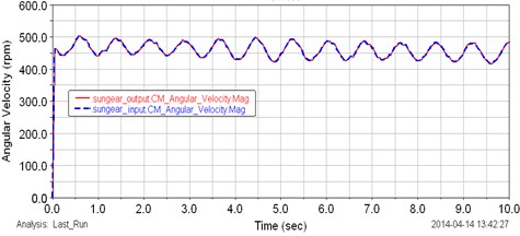
Fig. 11The plot of the torque of the sun gears
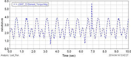
Fig. 12The plot of the angular speed of the input planet gears
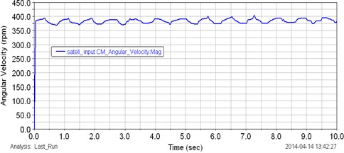
Fig. 13The plot of the angular speed of the output planet gears
Computed results of contact forces of the input planet gears and input sun gear are presented in Fig. 15, which is related to Fig. 5, the contact force is marked as number 2. The plot shows that the highest contact force of 7.5 N appears at 7. These gears overcome suddenly change of load at 7 second. Fig. 16 shows the plot of the computed contact forces between output satellites and output epicyclic internal gear, which is related to Fig. 6, the contact force is marked as number 3. In Fig. 16, the approximately highest contact force of 7.5 N appears two times at 6 and 7 seconds.
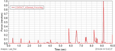
Computed results of contact forces of the output planet gears and output sun gear are presented in Fig. 17, which is related to Fig. 6, the contact force is marked as number 4. In this plot the highest contact forces appears at 9 second then torque decreases. The maximum value of contact force is 9 N. Contact forces change suddenly if the applied external torque is variable with a big range of values and the applied load changes frequently. The peaks in Figs 14-17 can be thought as due mainly to friction at gear teeth contacts. Figs 14-17 show that the computed contact forces between gears are small to use the mechanism.
Fig. 14The plot of the contact forces between input planet gears and input internal ring gear in Fig. 5
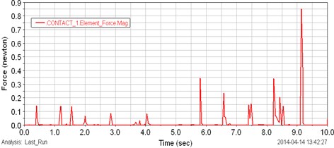
Fig. 15The plot of the contact forces between input planet gears and sun gear in Fig. 6
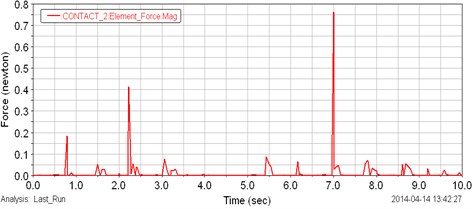
Fig. 16The plot of the contact forces between output planet gears and output internal ring gear in Fig. 6
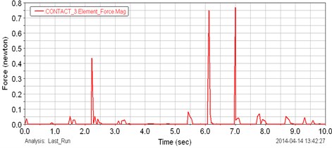
Fig. 17The plot of the contact forces between output planet gears and sun gear in Fig. 5
As can be observed results of study of a planetary drive with a virtual model it is possible to identify that the drive can adapt to a variable external load. The results show the proposed mechanism has suitable outputs both in terms of speed and torque. Simulation results of proposed mechanism show the mechanism has capability to adapt to a variable applied load. Results show that the mechanism can smoothly changes the reduction ratio at constant input speed of motor.
6. Conclusions
The proposed planetary mechanism with 2 DOFs has been studied from aspects of mechanical design and kinematic modeling. Design of the proposed mechanism is presented in kinematic scheme. In order to check the general feasibility of the mechanism numerical simulation with virtual model was carried out in ADAMS. Results show that the proposed solution for a planetary drive has good output parameters both in terms of speed and torque. The results also show that the proposed drive is able to smoothly change the reduction ratio. The main achievement of the study is the new design solution for a planetary mechanism with two degrees of freedom which is able to generate a variable reduction ratio. Obtained results are suitable for using the proposed design of planetary drive in wind mills.
References
-
Kaharman A., Ding H. A methodology to predict surface wear of planetary gears under dynamic conditions. Mechanics Based Design of Structures and Machines, Vol. 38, 2010, p. 493-515.
-
Yaghoubi M., Mohtasebi S. Design and simulation of a new bevel multi-speed gearbox for automatic gearboxes. Science Journal Report and Opinion, Vol. 2, 2010, p. 1-7.
-
Balbayev G., Carbone G. A dynamic simulation of a novel continuous variable transmission. Proceedings of The 11th IFToMM International Symposium on Science of Mechanisms and Machines, Vol. 18, 2013, p. 109-116.
-
Levai Z. Structure and analysis of planetary gear trains. Journal Mechanisms, Vol. 3, 1968, p. 131-148.
-
Carbone G., Mangialardi L., Bonsen B., Tursi C., Veenhuizen P. A. CVT dynamics: theory and experiments. Mechanism and Machine Theory, Vol. 42, 2007, p. 409-428.
-
Balbayev G., Ceccarelli M. Design and characterization of a new planetary gear box. Mechanisms, Transmissions and Applications, Mechanisms and Machine Science, Vol. 17, 2013, p. 91-98.
-
Thirumurugan R., Muthuveerappan G. Critical loading points for maximum fillet and contact stresses in normal and high contact ratio spur gears based on load sharing ratio. Mechanics Based Design of Structures and Machines, Vol. 39, Issue 1, 2011, p. 118-141.
-
Nenov P., Varbanov V., Angelova E., Kaloyanov B. Design and optimization of cylindrical gear 8drives based on ISO 6336. Balkan Journal of Mechanical Transmissions (BJMT), Vol. 2, Issue 1, 2012, p. 51-60.
-
Ivanov K., Balbayev G., Shingisov B., Watchanachai J. Adaptive drive of wind turbine generator. Rajamangala University of Technology Tawan – Ok Research Journal, Vol. 6, Issue 2, 2013, p. 44-47.
-
Derek F. L., Dennis W. H. The operation and kinematic analysis of a novel cam-based infinitely variable transmission. ASME International Design Engineering Technical Conferences and Information in Engineering Conference, Philadelphia, Vol. 3, 2006, p. 1-6.
-
Fetvaci C. Definition of involute spur gear profiles generated by gear-type sharper cutters. Mechanics Based Design of Structures and Machines, Vol. 38, Issue 4, 2010, p. 481-492.
-
Muni D. V., Muthuveerappan G. A comprehensive study on the asymmetric internal spur gear drives through direct and conventional gear design. Mechanics Based Design of Structures and Machines, Vol. 37, Issue 4, 2009, p. 431-461.
-
Patel P. Design and Analysis of Differential Gearbox. Report, U.V. Patelcolliege of Engineering, Ganpat University, Kherva, 2009.
About this article

