Abstract
Different track typologies compel different dynamic behaviors. Thus, the sleepers’ material can play a key role in the wheel-rail contact forces and vibration generation phenomena. Furthermore, this situation can be increased if the vehicle speed is varied, accelerating track damages and maintenance operations. In order to assess the influence of sleepers’ materials and vehicle speed on the vibration generation phenomenon, this paper develops a vehicle-track interaction model by means of a Finite Elements model in ANSYS commercial software. The numerical model is calibrated and validated with real data and then used to compare the different response of a ballasted track with concrete and wooden sleepers and accelerating and braking trains in both time and frequency domains. The results indicate the importance of sleepers’ stiffness in the vibration generation phenomenon as well as the low sensitivity of vertical deflections to variations in the train speed.
1. Introduction
The main roles of sleepers in the track system are the proper transmission of loads from rail to the ballast layer and the maintenance of track geometry. For these purposes, since the safety and quality of railway operations will depend on the sleeper behavior, it is crucial to ensure their adequate maintenance.
Traditionally, wooden sleepers have been predominantly used because of their great workability [1]. However, in recent decades, the use of new materials such as concrete, steel or polymers is being imposed due to their improved structural strength and their greater durability in adverse environments [2].
If wooden and concrete sleepers are compared, the following conclusions can be drawn. First, from an economic point of view, concrete sleepers are more expensive to produce and require specialized machinery during the installation because of their heavy weight. Nevertheless, they exhibit lower sensitivity to mechanical or biological degradation, which leads to longer life and lower maintenance costs. Second, from a structural point of view, the higher stiffness of concrete sleepers compels two main aspects. On the one hand, according to experimental studies as the one carried out by Sadeghi and Barati [3], stress transmission is more uniform than in the flexible sleepers, which can improve the maintenance of the infrastructure. On the other hand, according theorical studies as the one carried out by Zakeri and Rezvani [4], concrete sleepers present greater vulnerability to derailment.
In order to compare the vibrational response of both sleepers, recent experimental investigations, as those carried out by Real et al. [5] in a stretch of track with alternating wooden and concrete sleepers, showed that the vibrational response obtained in concrete sleepers was substantially lower than the one obtained in wooden sleepers. However, the different stiffness of railpads influenced the wave propagations. Thus, softer pads forced vibrations to be propagated through the rail (which could affect to the vehicle), whereas stiffer railpads forced vibrations to be propagated through the ballast layer (which could affect neighboring buildings).
These facts, apart from affecting comfort and safety in railway operations, might compel several variations in the vehicle and infrastructure maintenance policies. In this sense, numerical models have been imposed as an effective tool to predict railway vibrations against different scenarios. Thus, authors as Auersch [6], Galvín et al. [7] or Kouroussis and Verlinden [8] developed numerical models in which the track was simulated by means of Finite Elements, while the vehicle was modeled through a multi-body model, obtaining several conclusions about the influence of track characteristics on vehicle-track dynamics. Other authors, as Bruni et al. [9], adopted this methodology in their investigations showing the influence of track damping and stiffness on vehicle-track dynamics.
In accordance with these investigations, the present paper aims to analyze the dynamic behavior of the track through numerical train-track simulations. For this purpose, two numerical models of a layered straight track, one for each sleeper material, are developed and then coupled to a vehicle model simulated as a multi-body. These models are calibrated with real data and afterwards are used to assess the influence sleepers’ material on track dynamics under two scenarios: vehicle accelerating and vehicle braking.
2. Case of study
The studied stretch (Fig. 1) is a 300 meters long track located close to a railway station in which a sleeper material variation takes place.
It is a ballasted track with UIC-54 rails which lie on wooden sleepers with steel railpads and concrete sleepers with elastic railpads. Beneath the ballast layer, a vast clays layer takes place. The mechanical characteristics of the track materials are shown in Table 1, where represents Young’s modulus; represents Poisson’s ratio and represents the density.
Fig. 1Studied stretch of track
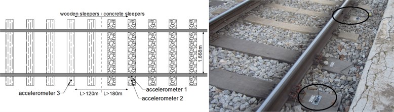
Table 1Mechanical characteristics of track materials
(MPa) | (kg/m3) | ||
Rail | 2.1·105 | 0.3 | 7850 |
Steel railpad | 595 | 0.3 | 900 |
Elastic railpad | 119 | 0.3 | 7850 |
Wooden sleeper | 1.382·104 | 0.3 | 690 |
Concrete sleeper | 27000 | 0.3 | 2400 |
Ballast | 50* | 0.2 | 1900 |
Clays | 600* | 0.3 | 2000 |
Platform concrete | 2.7·104 | 0.25 | 2400 |
*This properties will be subjected to a calibration process | |||
Two different track sections were instrumented during the data gathering campaign. In the first section, two accelerometers were located. The first one (accelerometer 1) was located on the rail web, while the second one (accelerometer 2) was located on the concrete sleeper surface. Meanwhile, a third accelerometer was located in the second section on the wooden sleeper surface (accelerometer 3). In all cases, SEQUOIA FAST TRACER accelerometers were used, which main characteristics are shown in Table 2.
Table 2Main characteristics of the accelerometers used during the data gathering campaign
Rail | Concrete sleeper | Wooden sleeper | |
Accelerations range (m/s2) | ±180 | ±180 | ±50 |
Frequency range (Hz) | [0-2500] | [0-2500] | [0-2500] |
3. Vehicle-track FE model
In order to represent the wheel-rail dynamics, two 3D FE models are developed using commercial software ANSYS LS-DYNA V 14. The first one (model 1) represents the concrete sleepers stretch, while the second one (model 2) represents the wooden sleepers stretch. In both cases, the vehicle is performed as a multi-body system, while the track is performed as a mesh of hexahedral calculation elements. The vehicle-track dynamics are studied in both time and frequency domains.
3.1. FE track models
Both 3D FE models (Fig. 2) are developed according to the computational considerations shown in [10]. Thus, all track components are reduced to a mesh of hexahedral elements in which the equation of motion (Eq. (1)) is solved. In this expression, [] is the mass matrix, [] is the damping matrix, [] is the stiffness matrix, is the displacement vector, is the velocity vector, is the acceleration vector and {} is the external forces vector:
Fig. 2Track model of concrete sleepers
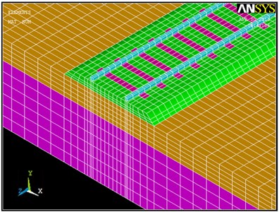
As Fig. 2 shows, both FE models represent the same stretch of track but are provided with different sleeper materials. Thus, model 1 is provided with concrete sleepers, while model 2 is provided with wooden sleepers.
In practice, the wooden and concrete sleepers’ geometry is different. Nevertheless, this variation is not performed in the FE models, where they are modeled as a prismatic element with constant section. For this purpose, in order to maintain the real flexural stiffness, the Young Modulus of each sleeper is set according to Eq. (2), where represents the product of inertia. Thus, the mesh and geometry of both models are kept but the mechanical properties are varied:
Additional simplifications are set in order to reduce the calculation times required. Thus, elastic-linear behavior of materials has been adopted and 8-nodes hexahedral elements have been selected to the model mesh. With regard to the model dimensions, in order to represent accurately the frequency range from 2 to 50 Hz, the model length has been set to 54 meters and the maximum size of the calculation elements has been set to 0.7 meters.
3.2. Multi-body vehicle model
The vehicle (Fig. 3) is modeled as a three-dimensional FE multi-body system of seven components (a car body, two bogies and four axles) and six degrees of freedom per element: , , displacements and the corresponding , and rotational angles. For this configuration, the equation of motion (Eq. (1)) is expressed as Eq. (3) according to [7] and solved in each vehicle component, where and respectively represent the accelerations, velocities and displacements of the element denoted by the subscript (car body), (bogie), (unsprung mass) or (rail). Furthermore, represents the gravity acceleration and represents the wheel-rail contact forces:
Fig. 3Multi-body vehicle model
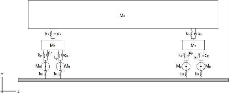
For finite element representation, 8-nodes hexahedral elements were selected for both car body and bogies, while mass elements were selected for wheels. Meanwhile, springs and dampers were selected to represent primary and secondary suspension. Finally, the wheel/rail contact is modeled by means of a Hertzian spring according to [11], who demonstrated the more realistic approximation that involves modeling the wheel/rail contact by means of linear and non-linear elements. The main properties of the aforementioned components are shown in Table 3.
Table 3Vehicle parameters assigned
Car body mass () | 34000 kg | Primary suspension stiffness () | 1.2 MN/m |
Bogie mass () | 4000 kg | Primary suspension damping () | 0.03 Ns/m |
Unsprung mass () | 1500 kg | Secondary suspension stiffness () | 0.55 MN/m |
Hertzian contact stiffness () | 2.8·109 N/m | Secondary suspension damping () | 0.098 MNs/m |
3.3. Vehicle-track interaction
Once both vehicle and track are modeled, the pass of the vehicle trough the model 1 is simulated. For this purpose, the vertical displacements of both rail and Hertzian spring are coupled during the first time step ( 0). Then, the vehicle is moved from one track section to another ( direction) every time step (Fig. 4). Hence, the load application process is the consequence of the different wheel-rail contact forces calculated in each load step.
Fig. 4Vehicle movement through the track for time steps n; n+i and n+j

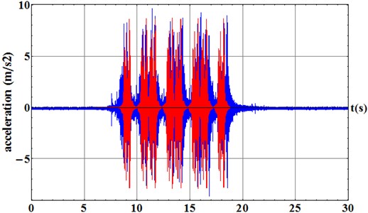
Fig. 5Comparison between the vertical accelerations of the FE model 1 (red) and data gathering campaign (blue)
a) Sleeper surface
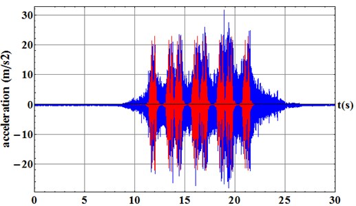
b) Rail web
Once the simulation is carried out, the superposition principle is applied to represent the pass of the whole vehicle through the track. Then, in order to certify the validity of the numerical simulations, a comparison between the vertical accelerations obtained in the FE model and those obtained during the data gathering campaign is carried out in both FE models of wooden and concrete sleepers. For the first one (model 1) the comparisons of the accelerations in both rail web (Fig. 5(a)) and sleeper surface (Fig. 5(b)).
The previous figures show a good adjustment between the numerical results and the real registers obtained in concrete sleepers. The maximum peaks and time-scaling match but some differences between the decay rates in the sleeper accelerogram are shown. These differences are caused by the frequency range studied (2-50 Hz). Thus, if the frequency range is delimited, the waves associated with the frequencies outside the studied range may not be fully developed. This fact compels a mismatch in the morphology between the accelerograms obtained from the numerical model and those obtained in the data gathering campaign. Nevertheless, these differences are completely acceptable since the maximum acceleration peaks are accurately performed.
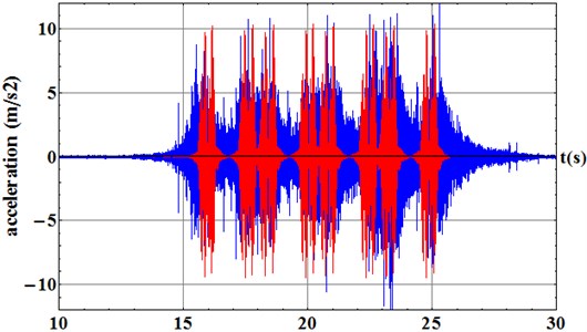
Once the simulation is performed in model 1, the sleepers’ mechanical properties are varied, obtaining the multi-body FE model of the wooden sleepers track (model 2). Then, the same simulation is carried out and a time domain comparison of vertical accelerations on the sleeper surface is performed (Fig. 6).
The same conclusions can be drawn. A good correlation between the maximum peaks and time-scaling is achieved but less relevant differences between the accelerograms morphology are shown due to the frequency range studied. Hence, according to the above results, the multi-body FE model is finally calibrated and validated and new conclusions can be obtained.
Fig. 6Comparison between the FE model 2 results (red) and data gathering campaign (blue). Results obtained in the sleeper surface
4. Numerical results
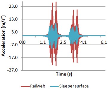
Once the numerical model is calibrated and validated, in order to evaluate the differences between the dynamic behavior of concrete and wooden sleepers, their vibrational response is studied in time and frequency domain. Firstly, time domain comparisons between them are shown below (Fig. 7).
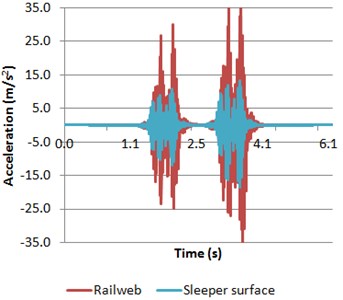
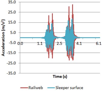
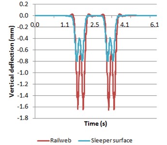
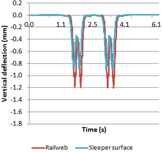
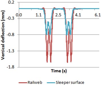
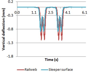
With regard to the time domain (Fig. 7), it is shown that the vibrational response of the track elements is quite different depending on the material of track sleeper. Thus, the accelerations registered in the rail web are higher in model 1 than in model 2. By contrast, the accelerations registered in the sleeper surface are lower in model 1 than in model 2. These differences may be caused by the different stiffness of the rail pad, which compels differences in the vertical deflections of both rails and sleepers (Fig. 8).
In the case of concrete sleepers, a softer pad is placed, which increases the deflections and accelerations registered in the rail web and decreases those obtained in the sleeper surface. By contrast, the opposite behavior is shown in wooden sleepers (where stiffer rail pads are set).
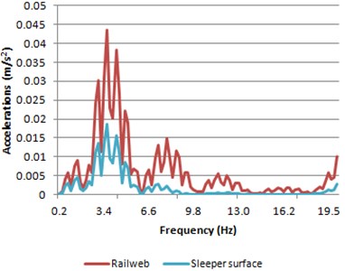
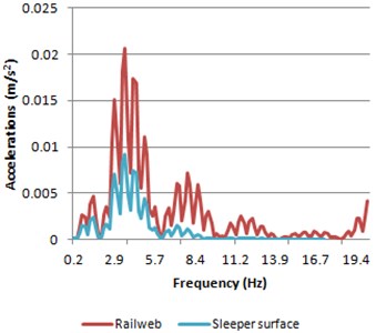
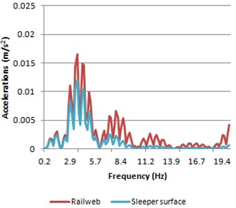
The same comparison is carried out in the frequency domain. Thus, the accelerations spectra of rail web (Fig. 9(a)) and sleeper surface (Fig. 9(b)).
Fig. 7Accelerations of both rail web and sleeper surface
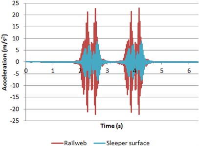
a) Model 1
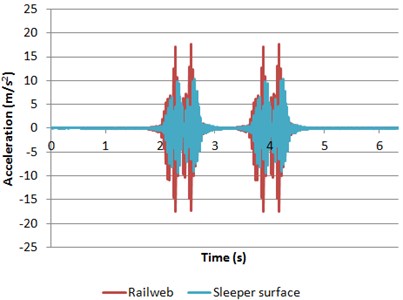
b) Model 2
Fig. 8Deflections of both rail web and sleeper surface
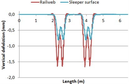
a) Model 1
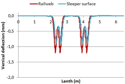
b) Model 2
Fig. 9Accelerations spectra of both rail web and sleeper surface
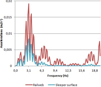
a) Model 1
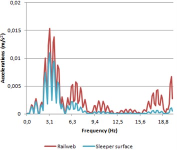
b) Model 2
As expected, accelerations spectra (Fig. 9) show a similar behavior than the obtained in the time domain. The accelerations spectrum in rail web presents higher results in model 1 than in model 2. By contrast, the results in the sleeper are lower in concrete sleepers track than in track provided with wooden sleepers. Furthermore, a similar morphological behavior of both models is achieved when comparing their spectra, excluding the peak at a frequency close to 4 Hz. This peak corresponds to the frequency associated to the pass of two axles of a same bogie.
Therefore, once the time and frequency domain results have been compared, it is possible to conclude an existing quite different behavior between both tracks. The accelerations in rail web are higher in model 1 in both time and frequency domain. The opposite behavior is presented in model 2 results. The trend is the same in the vertical deflections.
5. Studied cases
In the previous section the results for both models when the vehicle runs at a constant speed of 30 km/h are compared. Now, two different models have been developed. In these models the train travels at a variable speed, in order to reproduce the behavior of the vehicle accelerating and braking.
In the model with the vehicle accelerating, the train starts at a speed of 27 km/h and increases its speed to 80 km/h after 54 meters. In the case of the train braking, the vehicle runs at 50 km/h and decreases its speed to 22 km/h after 54 meters. The results have been obtained in both cases when the first axle of the train runs at a speed of 30 km/h, reaching this speed in the same point in both models.
5.1. Accelerating train
Comparing the results obtained from both models with the vehicle accelerating, it is shown that the trend is still the same. The accelerations calculated are higher in the rail web in the model 1, while the sleeper accelerations are higher in the model 2. Nonetheless, the results show higher accelerations in the second bogie relative to the first in both models. It is produced by two factors. Firstly, the second bogie runs though the measured point faster than the first due to the acceleration of the train. And secondly, the increasing speed might produce a dynamic overload caused by the acceleration of the vehicle, producing a movement of the sprung masses which cause greater excitation in the second bogie.
Fig. 10Accelerations of both rail web and sleeper surface
a) Model 1
b) Model 2
Comparing the vertical deflections, it is shown the same trend as in the case with constant train speed; even the amplitude of the displacements is nearly the same. The obtained vertical deflections are the same for the two bogies, in contrast to the results shown in Fig. 10. Other authors as Gia [12] demonstrated that the vertical accelerations are very sensitive to the circulation speed of the vehicle. It explains why the vertical accelerations calculated are different for the different axles with a small variation of the speed between them; and conversely the vertical deflection are slightly modified.
Comparing the results in the frequency domain, the spectrum is morphologically very similar to the one shown in Fig 9. However, the values of the peaks are higher, more than twice in the peak around 4 Hz, which corresponds to the pass of two axles of the same bogie. This makes sense due to higher accelerations that occurred in the track in the time domain. However, the increase in the time domain has not been as pronounced as it has been for the frequency domain.
The differences observed between both models when the train is accelerating follow the same trend as the original case with constant speed. Moreover, the accelerating vehicle clearly influence the vertical accelerations, which are very sensitive to the vehicle speed. However, these differences are not as appreciable in the vertical deflection as accelerations are.
Fig. 11Deflections of both rail web and sleeper surface
a) Model 1
b) Model 2
Fig. 12Accelerations spectra of both rail web and sleeper surface
a) Model 1
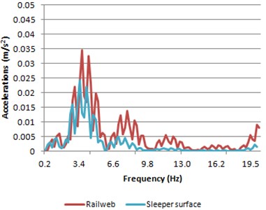
b) Model 2
5.2. Braking train
Comparing the accelerations calculated in both models when the train is braking, the same pattern is observed. Nevertheless, in this case, in contrast with the results sown in Section 5.1, the highest accelerations are registered in the first bogie. The main cause is the axle speed. Thus, the first and second axle speed is higher than the third and forth axle speed. In addition, a dynamic overload occurs in the front axles of the vehicle due to the inertia loads produced by the braking effect of the train.
In this case no significant differences are observed over previously calculated cases in Sections 4 and 5.1 for the vertical deflections. Therefore it can be stated that the effect of acceleration or braking of the vehicle has little importance when deflections in the rail web or the sleepers are studied. Nevertheless, the effect is greatly pronounced on the accelerations phenomenon.
The results in the frequency domain (Fig. 15) when the train is braking are morphologically the same to those obtained in the previous studied cases. Thus, in this case, the damped frequency is again corresponding with the axle pass of a same bogie.
The calculated results with the vehicle braking confirm the trend observed in the Section 5.1. The behavior differences between the model 1 and the model 2 are independent of the train speed. In all cases, the differences have shown the same pattern. However, the calculated accelerations are quite different depending on the vehicle speed in each instant of time, presenting differences even between axles of a same vehicle.
Fig. 13Accelerations of both rail web and sleeper surface obtained when the vehicle is braking
a) Model 1
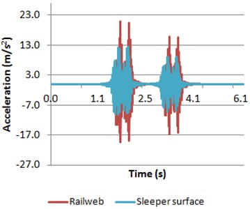
b) Model 2
Fig. 14Deflections of both rail web and sleeper surface obtained when the vehicle is braking
a) Model 1
b) Model 2
Fig. 15Accelerations spectra of both rail web and sleeper surface
a) Model 1
b) Model 2
6. Conclusions
The current investigation develops a numerical FE model in the time domain, calibrated and validated with in situ measurements, with the aim of comparing the different response of a ballasted track with concrete and wood sleepers. The FE model takes into account the train-track interaction, being the vehicle modeled following with a multi-body approach. In order to go more deeply in the comparison, the train is simulated to circulate at a variable speed, accelerating and braking. The following conclusions have been obtained:
• The accelerations on the rail are higher in the model 1. However, higher accelerations on the sleepers have been obtained in model 2. The main cause is the different stiffness of the rail pad of each model. Thus, a stiffer pad transmits the waves to the sleeper producing a higher vibrational response in the sleeper and lower in the rail. This trend is the same for the different train speeds considered.
• The accelerations calculated have different behavior depending if the train is accelerating, braking or running at a constant speed. The vertical vibrations in rail and sleeper are highly sensitive to the train speed. A deeply study of the dynamic effects of the vehicle should be performed to obtain a better knowledge of the phenomenon.
• The vertical deflections are less sensitive to the train speed, having no significant differences in the three studied cases.
• The study of the results in frequency domain at low frequencies [0-20 Hz] has shown that the more relevant frequency is the corresponding to the pass of two consecutive axles. This predominant frequency is also the most damped in all the cases.
References
-
Manalo A., Aravinthan T., Karunasena W., Ticoalu A. A review of alternative materials for replacing existing timber sleepers. Composite Structures, Vol, 92, Issue 3, 2010, p. 603-611.
-
Ferdous W., Manalo A. Failures of mainline railway sleepers and suggested remedies – review of current practice. Engineering Failure Analysis, Vol. 44, 2014, p. 17-35.
-
Sadeghi J. Field investigation on vibration behavior of railway track systems. International Journal of Civil Engineering, IUST, Vol. 8, Issue 3, 2010, p. 232-241.
-
Zakeri J. A., Rezvani F. H. Failures of railway concrete sleepers during service life. International Journal of Construction Engineering and Management, Vol. 1, Issue 1, 2012, p. 1-5.
-
Real J., Zamorano C., Asensio T., Montalbán L. Comparison of the effect of different sleeper typologies and track layout on railway vibrations. Latin American Journal of Solids and Structures, Vol. 11, Issue 12, 2014, p. 2241-2254.
-
Auersch L. The excitation of ground vibration by rail traffic: theory of vehicle-track-soil interaction and measurements on high-speed lines. Journal of Sound and Vibration, Vol. 284, Issue 1, 2005, p. 103-132.
-
Galvín P., Romero A., Domínguez J. Fully three-dimensional analysis of high-speed train-track-soil-structure dynamic interaction. Journal of Sound and Vibration, Vol. 329, Issue 24, 2010, p. 5147-5163.
-
Kouroussis G., Verlinden O. Prediction of railway induced ground vibration through multibody and finite element modelling. Mechanical Sciences, Vol. 4, Issue 1, 2013, p. 167-183.
-
Bruni S., Anastasopoulos I., Alfi S., Van Leuven A., Gazetas G. Effects of train impacts on urban turnouts: modelling and validation through measurements. Journal of Sound and Vibration, Vol. 324, Issue 3, 2009, p. 666-689.
-
Real J. I., Zamorano C., Comendador R., Real T. Computational considerations of 3-D finite element method models of railway vibration prediction in ballasted tracks. Journal of Vibroengineering, Vol. 16, Issue 4, 2014, p. 1709-1722.
-
Antolín P., Zhang N., Goicolea J. M., Xia H., Astiz M. Á., Oliva J. Consideration of nonlinear wheel-rail contact forces for dynamic vehicle-bridge interaction in high-speed railways. Journal of Sound and Vibration, Vol. 332, Issue 5, 2013, p. 1231-1251.
About this article
