Abstract
In recent years, the processing technology of advanced machinery has toward precision, high-performance, and high-speed. Therefore micro-fabrication becomes more important such as the getting smaller aperture in the printed circuit board (PCB), it tends to be more severe due to vibration. The vibration has adverse effects to machining accuracy and surface roughness which will increase tool abrasion and further accelerate the destruction from material fatigue. There are many ways to produce perforations, such as laser micro-machining and micro-drilling. The industry still adopts micro drill piercing process due to the cost and technical considerations. In order to enhance the cutlery life and the quality of the drilling process, the cutting characteristic of bur is important. Hence, the vibration during drilling must be suppressed. This study is to investigate the dynamic analysis of a micro drill under ultrasonic vibration (50 kHz) excited with a piezoelectric-driven actuator experimentally and numerically by using finite element analysis. The results show that the vibration and the cutting forces are effectively reduced and thereby the cutting performance is improved when introduces ultrasonic vibrations during micro-drilling process.
1. Introduction
High-speed micro-drill is one of the important micro-fabrication technologies. In drilling, due to the miniaturized cutlery and higher spindle speed, more quality and precision issues need to be considered, such as the type, stiffness, rigidity of the tool, cutting force and cutting process vibration problems, etc. If the excessive cutting force and vibration occurred, it will produce buckling and even fracture the bit. That will reduce the precision, damage the product, and severely increase the process period and cost.
Since cutting technology has been developed for quite some time, there are plenty rich improvements on the drilling in the literature.
Lei et al. [1] fabricated nano-crystalline diamond (NCD) coated printed circuit broad (PCB) micro drills by the hot filament chemical vapor deposition (HFCVD) technique. They have optimized the corresponding pretreatment and deposition parameters including pretreatment zone, pretreatment time in Murakami’s reagent, substrate temperature during the deposition process, as well as the deposition time. Aziz et al. [2] proved that the applications of ultrasonic vibration (USV) lead to an optimum web thickness of a long flat drill in the best drilling performance and a longer tool life. However, there was no improvement of drilling performance in boring with step feeding method.
Investigations as Yao et al. [3-5] used three different material layers coated on the surface of the micro-drills to bore the actual PCB and to investigate the tribological behavior, the impact of wear resistance and the lubricity of different coatings during drilling experimentally. Gong et al. [6] analyzed the effect of the geometry, boundary conditions, rotation speed, buckling load, cross-sectional area and critical velocity to the micro-drill by FEM. Hinds and Treanor [7] investigated the stress distribution of micro-drill by FEM. Young [8] used drill trough shape with geometric formulas to derive numerical analysis MATLAB program and to calculate the grinding wheel bus of a drill slot. Graphic software CATIA is adopted for machining simulation of the experimental model in comparison with the actual products to verify the accuracy and usefulness of this model. The module of a drill slot grinding wheel bus is used subsequently to improve its geometry.
Some researchers as Hindsa [9-11] studied the high speed micro drill production process of boreholes based on Euler-Beam theoretical model to establish the equations of motion by FEM and to validate with experiments. The impact of the holes offset of PCB is then explored through load carried by different diameters and variations on the micro drill spindle speed. The geometry effects on a micro drilling performance have been studied by Hindsa et al. [12, 13]. These investigations studied the four important design elements including drill sharp angle, helix angle, thickness and bevel chisel via fractional factorial experimental design, and analysis of variance in order to obtain the influence of drill cutting force, abrasion and hole position accuracy of PCB between design factors and their interactions. Yoon et al. [5, 14, 15] employed Taguchi method to find the best parameter for drilling ten laminates PCB by micro drills. Image processing tool with microscope and CCD is developed to measure the wear characteristics of the PCB after boring. Kim [16] identified the impact of the PCB drilling parameters and quality of a micro drill by using the Design of Experiment (DOE) method. Huang and Wu [17] established the equation of motion of an ultrahigh speed drilling and investigated the effects of various parameters on the dynamic characteristics of the high-speed drill.
Although there were quite rich improvements on the drilling in the literature, only few studies employed ultrasonic technique during the boring process. This paper is to add a slight ultrasonic vibration (50 kHz) at high-speed micro-drilling process to improve the dynamic characteristics in general drilling process numerically (finite element method, FEM) and experimentally.
Fig. 1A typical micro drill (cm)
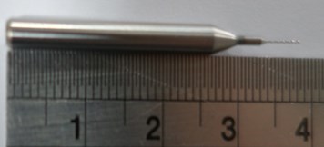
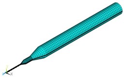
Fig. 23D geometric model with mapped mesh of a typical micro drill
2. Finite element configuration
A typical tungsten carbide micro drill chosen for this study is shown in Fig. 1. The mechanical properties of the tungsten carbide drill are Young’s modulus of 706 GPa, density of 8,356 kg/m3 and Poisson’s ratio of 0.18. The diameter and body length of the drill bit are 0.3 mm and 5.5 mm, respectively. The total length including shank is 38 mm. The dimension of each part of the micro drill is measured and input in SolidWorks to build the physical geometry of the drill. Then, it is imported into ANSYS (FEM analysis software) to obtain the dynamic characteristic of the micro drill by using modal, transient, buckling, and steady-state analyzer of ANSYS. In ANASYS, the element Solid45 is used for the analysis. The lowest three natural frequencies will be converged if the element number is over 100,000. So, the 110,000 elements are considered to study in this work. The 3D geometric model with mapped mesh of the micro drill is shown in Fig. 2. The boundary conditions are set to zero except only axis rotation is allowed at the center end of the shank.
The main purpose of this article is to analyze the dynamic characteristics and the buckling force of a micro drill with or without ultrasonic effect produced by a piezoelectric (PZT) material attached at the other side of the PCB.
3. Experimental set up
For the cutting load and vibration measurement, the load cell and accelerometer are employed to study. In this experimental analysis, an analyzer Hp35670A and a high speed spindle, maximum speed 160,000 rpm, are considered. The experimental analysis is divided into four parts. The ultrasonic effect produced by the vibration of a piezoelectric patch will be examined in each part of the experiment. The first part is to measure the vibration generated during the drilling of the electricity board with different drill diameter, rotation speed, feed speed, piezoelectric voltage and the frequency, etc. The vibration signal is captured through an accelerometer and is transmitted to the spectrum analyzer through the fast Fourier transform to generate the frequency spectrum diagram. In this experiment, the load cell and monitor are unused. The experimental setup is shown in Fig. 3. The voltage amplifier can be turned on or off to present the piezoelectric vibration module or not, respectively.
The second part of the experiment is to investigate when drills electricity boards. The force signal is measured by the load cell and is displayed and recorded by the load monitor. The third and fourth part are to observe the chip and hole wall condition of the PCB after boring for different rotation speed with or without piezoelectricity effect. In this experiment, the load cell and monitor are used while the accelerometer is not, as shown in Fig. 3(a). A photo of experimental setup is displayed in Fig. 3(b). A piezoelectric-driven actuator is attached under the workpiece and a high speed spindle with a micro drill is also found in this figure.
Fig. 3The experimental setup of vibration amplitude and cutting force measurement during drilling
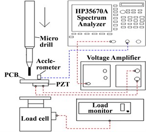
a) A schematic diagram
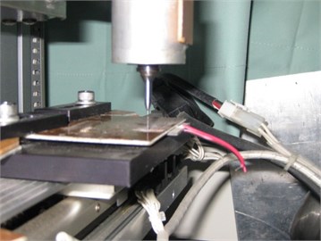
b) A photo of experimental setup
4. Result and discussion
This study is to investigate the dynamic characteristics of the micro drill and PCB structure with piezoelectricity effect. The steady state, modal, transient and buckling analysis by the FEM and the experimental results are discussed in the following subsections.
4.1. Finite element analysis
In the finite element analysis, the steady-state analysis, modal analysis, buckling analysis and transient analysis are discussed. In actual situation, the piezoelectric material is placed on the PCB and will produce simple harmonic motion relative to the micro drill in z axis direction. In finite element steady-state analysis, the harmonic excitation of the PZT is simulated by a periodic force applied at the end of the micro drill. The time response of the micro drill when applied the PZT harmonic excitation is shown in Fig. 4. This base excitation will cause the micro drill moving back and forth periodically through drilling process.
In modal analysis, the first three modes with or without small amount of PZT excitation are identical. The natural frequencies of the fourth and fifth modes drop less than 3 % with PZT excitation. The first mode shapes of the micro drill with or without PZT excitation are the same and the one with PZT excitation is shown in Fig. 5. In buckling analysis, the buckling forces are drop less than 1 % under piezoelectric excitation for the first 8 buckling modes.
In transient analysis, micro drill is applied to a 1 N force along axis for 0.02 seconds to simulate the impulse excitation. Time responses of the micro dill after the impact with and without PZT excitation are shown in Fig. 6(a) and (b), respectively. The response amplitude with PZT excitation attenuates to zero after 0.15 seconds as shown in Fig. 6(a). The other one without PZT excitation tends to settle after 0.30 seconds, twice longer than the one with PZT excitation, as shown in Fig. 6(b). Hence, the introduction of PZT stimulation will reduce the settling time in drilling process.
Fig. 4Harmonic motion of the micro drill in z axis excited by PZT
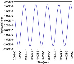
Fig. 5First mode shape of the micro drill with or without PZT excitation
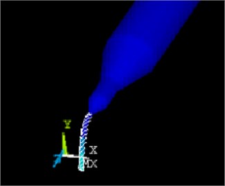
Fig. 6Transient response after 1 N, 0.02 seconds impact to the micro drill: a) with, b) without PZT excitation
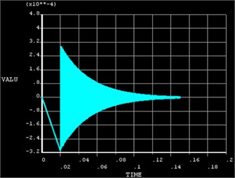
a)
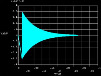
b)
4.2. Experimental analysis
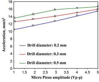
The experimental analysis will be discussed in four parts. Each will be compared with cases of drilling under the piezoelectric stimulation (PS case) and no PZT excitation (NP case). The first part is to measure the vibration generated during the drilling of the electricity board with different drill diameter, rotation speed, feed speed, piezoelectric voltage and the frequency, etc. Fig. 7 shows the measured vibration by varying the rotational speed with a 0.3 mm diameter micro drill, feed speed at 2 mm/s, PZT frequency at 50 KHz and voltage at 5 Vp-p (peak to peak voltage). The acceleration measured on the PCB with PZT stimulation (red line) is apparently lower than the one without PZT stimulation (blue line) during different rotating speed. The acceleration difference between them becomes larger when the rotating speed is increasing from 5,000 to 30,000 rpm. Fig. 8 shows the measured acceleration by varying the feed velocity from 2 to 4 mm/s with 0.3 mm diameter, rotating speed at 6,000 rpm, PZT frequency at 50 kHz and voltage at 5 Vp-p. Again, the acceleration values measured on the PCB with PZT excitation are lower than those without PZT excitation. The acceleration of the PCB affected by different frequencies of piezo for three different diameters: 0.2, 0.3 and 0.5 mm with feed speed 2 mm/s, rotating speed 6,000 rpm and PZT voltage 5 Vp-p, is shown in Fig. 9. When the frequency of the piezoelectric is 10 kHz, the acceleration of the PCB is 26 mm/s2 (for 0.3 mm diameter case) and it closes to the acceleration without piezo excitation, please refer to blue line in Fig. 8. When the piezo frequency is increased to 20 kHz and higher, the accelerations drop significantly for all three diameters. Basically, the maximum, median and minimum acceleration generated by micro drill are 0.5 mm, 0.3 mm and 0.2 mm, respectively. In changing the piezoelectric voltage, the vibration values are lower than those without PZT excitation. But the vibration of the PCB will increase when PZT voltage is enlarged for all three diameter sizes, as shown in Fig. 10.
Fig. 7Measured vibration by boring the PCB with a micro drill with 0.3 mm diameter, feed speed at 2 mm/s, PZT frequency at 50 kHz and voltage at 5Vp-p
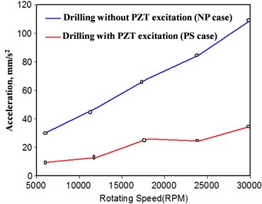
Fig. 8Measured vibration by boring the PCB with a micro drill with 0.3 mm diameter, rotating speed at 6000 rpm, PZT frequency at 50 kHz and voltage at 5 Vp-p
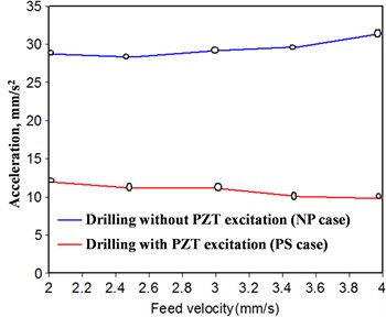
Fig. 9Measured vibration by boring the PCB with a micro drill with 0.3 mm diameter, feed speed 2 mm/s, rotating speed 6000 rpm and PZT voltage 5 Vp-p
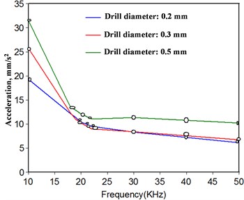
Fig. 10Measured vibration by boring the PCB with a micro drill with 0.3 mm diameter, feed speed at 2 mm/s, rotating speed at 6000 rpm and PZT frequency at 50 kHz
The second part of the experiment is to measure the cutting force when drilling the PCB by varying the rotating speed or feed velocity with fixed diameter micro drill, PZT frequency and voltage. Fig. 11 shows the measured cutting forces by varying the rotational speed from 5,000 to 30,000 rpm with a 0.3 mm diameter micro drill, feed speed at 2 mm/s, PZT frequency at 50 KHz and voltage at 5 Vp-p. The cutting force will both drop for PS and NP cases when it increases the rotating speed from 5,000 to 30,000 rpm. In general, the cutting forces of PS case are lower than that of the NP case. Fig. 12 shows the measured cutting forces by varying the feed velocity from 2 to 4.5 mm/s with a 0.3 mm diameter micro drill, rotating speed at 2 mm/s, PZT frequency at 50 KHz and voltage at 5 Vp-p. The cutting forces will increase when the feed speed is getting higher for both PS and NP cases. Again, the cutting forces of PS case are lower than that of the NP case.
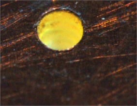
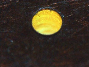
The third part of the experiment is the comparison of the holes smoothness after boring for both PS and NP cases. The holes are bored by 0.3 mm diameter micro drill with 2 mm/s feed speed, 6,000 rpm rotational speed, PZT frequency 50 KHz and voltage 5 Vp-p. It is unsatisfactory if the piezoelectric vibration chips remain on the surface. The bored hole is not clean and the chips remain on the inner surface of the hole with PZT excitation. When the piezo excitation frequency is lower and the voltage is larger, the surface of the bored hole is unsatisfactory, as shown in Fig. 13. Results show that the surface roughness is 42.07 μm as the drilling with the piezoelectric vibration, however, surface roughness is 41.42 μm as the drilling without the piezoelectric vibration. So, the surface roughness will be enlarged if the drilling with the piezoelectric vibration.
Fig. 11Measured cutting forces with a micro drill with 0.3 mm diameter, feed speed at 2 mm/s, PZT frequency at 50 kHz and voltage at 5 Vp-p
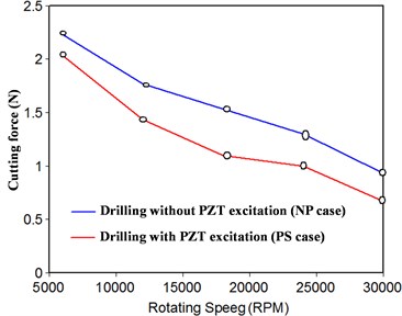
Fig. 12Measured cutting forces with a micro drill with 0.3 mm diameter, rotating speed at 6000 rpm, PZT frequency at 50 kHz and voltage at 5 Vp-p
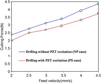
Fig. 13Bored hole of the PCB by a micro drill with 0.3 mm diameter, feed speed at 2 mm/s and rotating speed at 6000 rpm: a) with 50 KHz, 5 Vp-p, b) without PZT excitation
a)
b)
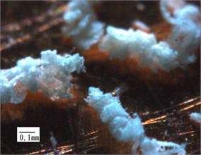
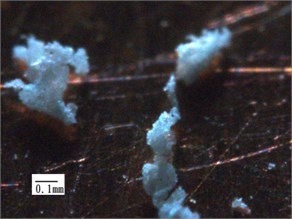
Fig. 14Chip from the bored hole of the PCB by a micro drill with 0.3 mm diameter, feed speed at 2 mm/s and rotating speed at 6000 rpm: a) with, b) without PZT excitation
a)
b)
The fourth part of the experiment is to compare the integrity of the left over chips after boring for both PS and NP cases. The drilling condition remains the same as the third part. As a result, the chips produced under PZT stimulation are more fragmented than the one without excitation. When the piezo excitation voltage is lower and the frequency is larger, the chips can be hold more complete, as shown in Fig. 14.
5. Conclusion
In micromachining, the various parameters such as rotating speed, feed rate, etc., have significant impact on the cutting tool. Some severe cases can affect the accuracy of the tool and even damage the cutlery. So it is the key issue to maintain the good quality of drilling and micro-machining cutting characteristics.
This paper employed finite element and experimental analysis is to explore differences in the cutting characteristics after introducing tiny piezoelectric vibration. And the analysis of this paper is concluded as follows:
1. In numerical analysis, when introducing piezoelectric ultrasonic vibration, the natural frequencies and buckling mode will decline. Also, the damping effect is better and the settling time is shorter.
2. When the ultrasonic vibrations have involved in high speed cutting process, the vibration and cutting forces measured from the PCB are effectively reduced in different rotational speed and feed velocity.
3. The measured vibration of the PCB boring by the drill with smaller diameter is lower than that with larger diameter.
4. The vibration suppressing effect is poor when the voltage of the piezoelectric is increased and the frequency of the piezoelectric vibration is lower than 10 kHz.
5. When introduce piezoelectric ultrasonic vibration, the wall surface of the bored hole on the PCB is not clean and smooth, and the left over chips show more fragmentation phenomenon. When use high frequency or lower voltage of the piezoelectric material, the surface of the bored hole is more desirable and the chip is more complete.
References
-
Lei X., Shen B., Cheng L., Sun F., Chen M. Influence of pretreatment and deposition parameters on the properties and cutting performance of NCD coated PCB micro drills. International Journal of Refractory Metals and Hard Materials, Vol. 43, 2014, p. 30-41.
-
Aziz M., Osamu O. O., Onikura H. Novel micro deep drilling using micro long flat drill with ultrasonic vibration. Precision Engineering, Vol. 36, 2012, p. 168-174.
-
Yao S. H. Evaluation of TiN/AlN nano-multilayer coatings on drills used for micro-drilling. Surface and Coatings Technology, Vol. 197, Issues 2-3, 2005, p. 351-357.
-
Kang M. C., Je S. K., Kim K. H., Shin B. S., Kwon D. H., Kim J. S. Cutting performance of CrN-based coatings tool deposited by hybrid coating method for micro drilling applications. Surface and Coatings Technology, Vol. 202, Issues 22-23, 2008, p. 5629-5632.
-
Yoon H. S., Wu R., Lee T. M., Ahn S. H. Geometric optimization of micro drills using Taguchi methods and response surface methodology. International Journal of Precision Engineering and Manufacturing, Vol. 12, Issue 5, 2011, p. 871-875.
-
Gong Y. P., Ehmann K. F., Lin C. Analysis of dynamic characteristics of micro-drills. Journal of Materials Processing Technology, Vol. 141, 2003, p. 16-28.
-
Hinds B. K., Treanor G. M. Analysis of stresses in micro drillings the finite element method. International Journal of Machine Tools and Manufacture, Vol. 40, 2000, p.1443-1456.
-
Young H.T. Study and analysis on precision machining of microdrills. Proceedings of the Conference on National Science Council Result, Mechanical Engineering and Mechanics Section, Taiwan, 2003.
-
Strenkowskia J. S., Hsieha C. C., Shihb A. J. An analytical finite element technique for predicting thrust force and torque in drilling. International Journal of Machine Tools and Manufacture, Vol. 44, Issues 12-13, 2004, p. 1413-1421.
-
Gupta K., Ozdoganlar O. B., Kapoor S. G., DeVor R. E. Modeling and prediction of hole profile in drilling, part 1: modeling drill dynamics in the presence of drill alignment errors. Journal of Manufacturing Science and Engineering, Vol. 125, Issue 1, 2003, p. 6-13.
-
Huang B. W. The drilling vibration behavior of a twisted microdrill. Journal of Manufacturing Science and Engineering, Vol. 126, 2004, p.719-726.
-
Hindsa B. K., Treanorb G. M. Analysis of stresses in micro-drills using the finite element method. International Journal of Machine Tools and Manufacture, Vol. 40, Issue 10, 2000, p. 1443-1456.
-
Filiz S., Ozdoganlar O. B. A model for bending, torsional, and axial vibrations of micro- and macro-drills including actual drill geometry, part 1: model development and numerical solution. Journal of Manufacturing Science and Engineering, Vol. 132, Issue 4, 2010, p. 041018.
-
Kuar A. S., Doloi B., Bhattacharyya B. Modelling and analysis of pulsed Nd:YAG laser machining characteristics during micro-drilling of zirconia (ZrO2). International Journal of Machine Tools and Manufacture, Vol. 46, Issues 12-13, 2006, p. 1301-1310.
-
Huang C. K., Liao C. W., Huang A. P., Tarng Y. S. An automatic optical inspection of drill point defects for micro-drilling. The International Journal of Advanced Manufacturing Technology, Vol. 37, Issues 11-12, 2008, p. 1133-1145.
-
Kim D. W., Cho M. W., Seo T. I., Lee E. S. Application of design of experiment method for thrust force minimization in step-feed micro drilling. Sensors, Vol. 8, Issue 1, 2008, p. 211-221.
-
Huang B. W., Wu S. M. Analytical solution of free vibration of a high-speed drill. Proceedings of the Conference on National Science Council Result, Mechanical Engineering and Mechanics Section, Taiwan, 2000.
About this article
