Abstract
As a novel environmental sampling technique, sonic vibration drilling has been rapidly developed in the past few years. The penetration force is generated from two eccentric shafts driven by hydraulic motors. This gives rise to the vertical oscillation of the drill pipe to drill in the stratum. As the most important parts of the sonic driller, the vibration head consists of eccentric structure, synchronization mechanism, supporting structure and rotating structure. In the first part of this paper, a 3D mathematical model was developed after analyzing the working law of sonic vibration head by using SolidWork. In the second part, the model was stimulated in order to predict the performances of the sonic vibration head by using ANASYS. In the third part, a physical prototype was developed to conduct practical experiments, confirming feasibility of the previous design and stimulation, and making good references for future optimization.
1. Introduction
Sonic vibration drilling is a novel technique for environmental sampling that has been rapidly developed [1-3]. It is characterized by high drilling speed with no drilling mud needed. It can be widely used in mineral prospecting survey, geotechnical investigation construction, environmental and well drilling, being capable of extracting high-quality core, especially in sedimentary stratum [4]. The vibration head consists of eccentric structure, synchronization mechanism, supporting structure and rotating structure. It is the most important part of sonic driller [5]. Its vibration characteristics are closely related to drilling efficiency, economy and security during the sonic drilling. Therefore, design for the vibration head is of great importance [6].
Traditionally, design of the drilling rig is mainly based on the previous scheme [7] which consists of fixed parameters of main components [8]. The parameters are generally used to verify strength and toughness, making sure the rig safety performance. After this, a 2D engineering drawing is made to advance the physical prototype. For this method, it has disadvantages in wasting time due to the redesign of the rig if there is something wrong checked out. In order to avoid this, a dynamic design is introduced. In this method, the Virtual Prototype Technology (VPT) [9, 10] is applied to establish a three-dimensional model to make the stimulation, being capable of repeatedly revising the design of virtual prototype. The VPT ensures feasibility of the visual prototype in practical – it can be successfully processed with higher quality and shorter design period in comparison with traditional one [11].
In the first part of this paper, a 3D mathematical model was developed after analyzing the working law of the sonic vibration head by using SolidWork. In the second part, the model was stimulated mainly to predict the performances of the sonic vibration head by using ANASYS. In the third part, a physical prototype was developed and used to conduct some practical experiments to confirm the feasibility of the previous design and stimulation, and help figure out some drawbacks of the previous design, making good references for the future optimization.
2. Sonic vibration head design
2.1. The principle of sonic drilling processing
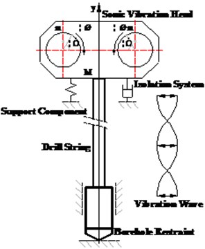
Fig. 1 plots working law of the sonic vibration head. A hydraulic motor drives two eccentric shafts to high speed move respectively. The force generated by eccentric shafts can be resolved into horizontal and vertical direction [12]. However, the overall horizontal components can be counteracted while the vertical can be strengthened due to the same magnitude speed but totally opposite direction of the two eccentric shafts’ move. This gives rise to the vertical oscillation of the drill pipe, whose high frequency can partially cause the earth nearby liquefied, effectively reducing the friction between the drilling tools and the layer around. It is, therefore, believed to be a highly efficient way to extract cores.
Fig. 1Principle of sonic drilling processing
2.2. The virtual prototype of the vibration head
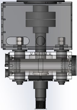
The vibration head is mainly used to generate exciting force. In addition to protecting the support plate from being damaged, an isolator is designed. The design of eccentric parts and isolation structure are vital to the design of the virtual prototyping. Specifically, the vibration head structurally consists of eccentric structure, synchronization mechanism, supporting structure and rotating structure. With four parts having been completed respectively, an overall 3D visual model is developed.
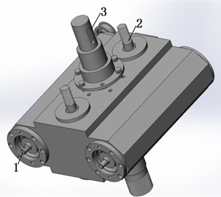
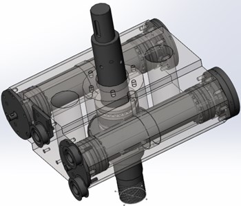
During the process of assembling the visual model, a cordwood-like system is used to make the model structures more clear for its future revision. This clearance is realized by the proper order of assembling, from smaller components like eccentric structure, isolator structure and supporting structure to the overall design (shown in Fig. 2).
Fig. 2Virtual prototype of the vibration head: 1. Eccentric parts, 2. Isolation structure, 3. Rotating structure, 4. Synchronization mechanism, 5. Support plate
2.3. Virtual prototyping design of the key parts
2.3.1. The virtual prototype of the synchronization mechanism
A double-eccentric shaft with simple structure is selected to ease the layout of the vibrator. The double-eccentric shaft consists of the eccentric shafts, support shafts, and hydraulic motor. These components are installed in the vibrator, which is driven by the eccentric shaft. The synchronous motion of the double eccentric shaft is to ensure high working efficiency of the vibration head. In order to keep the two eccentric shafts working synchronously, a group of structures are installed, including the synchronizing wheels, guide wheel, pressing wheel, and synchronous belt. Fig. 3 shows the virtual prototype of the synchronization mechanism.
Fig. 3Virtual prototype of the synchronization mechanism
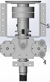
2.3.2. The virtual prototype of the isolation and support structure
When the audio vibration head works, an eccentric portion driven by the vibration will produce a periodic vertical vibration. The maximum exciting force can reach 180KN. Isolation 4. Test of the vibration head structure must be set up so that most of the exciting force down can be through the drill pipe on the role in the formation. Centrifugal force upward must be reduced to a minimum through isolator. Thus, the isolation structure must have upwards and downwards isolation capability in both directions.
Fig. 4Virtual prototype of the isolation and support structure
Isolation structure section includes a bolt pin, annular temperature isolator, locknut, adjusting gasket, and pin. Isolation bolted vibrator pins is suspended by the support structure, which is made by the support housing, instead of welding. This can reduce the area of stress concentration (shown in Fig. 4).
3. Model and simulation analysis
3.1. Mathematical model of the vibration head
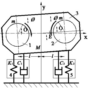
Based on the first virtual prototype acoustic vibration, the model with double eccentric shaft vibration head can be simplified as shown in Fig. 5. The eccentric system driven by a double-speed motor can produce vibration in direction , causing vibrating bodies vibrate simultaneously. However, body vibration isolator is simplified as a combination of damping and stiffness support, which can be used to reduce the vibration between vibration head and to protect the main components. In terms of the vibrating body, it can be simplified to a particle due to its large mass and small elastic body mass. The interaction force among bearings, eccentric shaft, and the sleeve body are regarded as the internal forces for vibration. But the symmetrical and metal vibration rubber components can move up and down. The symmetrical arrangement of metal can be thought as two parallel rubber damping bodies. However, the two isolator cannot move completely uniform, which can cause the vibrating body swing. The piled metal rubber cannot be regarded as a series of two damping rubber bodies. When the vibrating body moves downward, the vibration state is opposite during the upward movement of the vibrating body.
Metal rubber is a new type of vibration damping material. Its internal structure is intertwined wire mesh structure space collusion line into the rubber-like polymer structure [13-15]. By using a vibrating body metal rubber material, audio system is supported on the vibration head mounting bracket to reduce the impact of vibration. At the same time, it has a role in slowing the impact of vibration on the mounting bracket body system in sonic drilling.
Assume that the rotation of the eccentric shaft system quality, structure, moment of inertia, and resistance moment are completely equal. The motors are completely synchronized. On the one hand, if the vibration isolation system is not preloaded and compressed, the centroid of the vibrating body will stay at an initial position. On the other hand, the centroid will fall down by with generating a static angle due to gravity and preloaded compression force of ; vibration centroid will fall down by , and a swing angle of will generated with an inertia of , at which of the time the static deformation and deformation are generated by the system are respectively , , , and . The kinetic energy of the vibrating body can be expressed as:
Fig. 5Model of the vibration head driven by two eccentric rotating system: 1, 2. Two of eccentric rotating system, 3. Main vibration body, 4. Stiffness, 5. Damper
When considering the static deformation vibration isolation system, the potential energy system should include potential energy generated by elastic static deformation of the isolator. Two vibration isolators in total deformation force are and . The displacement of the centroid is , therefore, the overall potential is:
Energy dissipation function can be expressed as:
where and are damping coefficient of direction , and is drag torque coefficient. The resultant force of generalized exciting force and weight over bit is:
Substitute , , and into Lagrange equation, we can get:
Differential equations of vibration can be represented based on Lagrange equation:
Substitute Eqs. (5)-(12) into Eq. (13), we can get damped vibration equation of the vibration body expressed as:
Considering factors of and preloaded compression force, as the same as static elastic force of the isolator, two isolator centroid moments of static elastic shall be zero. It can be expressed as:
Substitute Eq. (15) into (14), we can get Eq. (16) which is the differential equation of damping forced vibration. Kinetic equation can be used for analysis – the vibration equation in direction is:
Dual-motor drive system inertia comes from two aspects: the eccentric rotation of the inertial force generated by the steady state and the inertia resultant force caused by the eccentric shaft angular acceleration changes. These two forces together constitute the exciting force excitation system. Thus, the sound frequency vibration motor is significantly vulnerable to the impact of instability. The bottom vibration load will feedback reversely with the changing of hydraulic flow reversely.
According to the vibration equation rotor dynamics equation, the single eccentric system can be expressed as:
In the above formula, the first term on the left is a rotary moment of inertia; the second axis is the friction torque; the third inertial is the torque generated by the moment of inertia force in the direction; and the fourth is the gravity eccentric shaft torque for each centroid.
As a system, vibrating body can transform the hydraulic energy into the excitation force as an output. The formulae for calculating the hydraulic motor power can be expressed as:
Eq. (18) can be explained based on the characteristic of hydraulic motor. Eccentric system is derived by hydraulic displacement motor. Pressure and flow are the two parameters to represent the hydraulic energy of motor input. Apart from a small portion of mechanical energy loss, all the rest can be converted into mechanical energy output, which can drive the eccentric shaft rotate. Since hydraulic motor has the minimum displacement of 0.49 cm3/r, it can work with high speed of 12000 rpm, meeting requirement of a high-speed hydraulic motor.
3.2. Models for finite element simulation
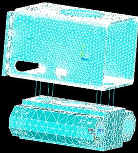
Vibration head is structurally complex. In order to facilitate simulation, structures of the sonic frequency vibration are simplified into three components: support housing, vibrating body (main vibration body) and isolation. The centrifugal eccentric structure can be directly replaced by the generating load. It is defined the supporting frame and the vibrating body as 45# steel material, with elastic modulus of 2.1E11, Poisson’s ratio of 0.3, and mass density of 7850 kg/m3. The type of the 3D solid model is applied to the support plate, which is divided by a free smart grid, setting the precision to the fourth. The solid 185 is selected as element type for the finite element model. The final number of the nodes and units are 101,042 and 432,499 respectively. The combination of spring – damper unit is used to simulate the vibration isolator whose mass is so small to be ignored. Each isolator is replaced by four springs, each of whom has the spring stiffness parameter 2.2E6, and damping 20 Ns/m.
During the working process of sonic drilling, the support frame is connected with the guide, where mini-range but zero displacement constraint is employed; the vibrator mainly works through the vertical movement in direction due to the force generated by eccentricity. Therefore, the constraints in direction and are employed on both sides of the midline. There are many small structures and features in vibration head, such as threaded holes, bosses and chamfers. It therefore will take up a lot of computing resources when calculating, which will make the meshing quality worse. Therefore, they have been simplified off as is shown in Fig. 6.
Fig. 6Finite element models
The overall modal analysis is made in this paper. During the audio rig works, the support is connected with the rail, and all directions at zero displacement constraints are imposed. Due to the presence of up and down of the vibrating body, constraints are imposed on both left and right sides of the center line and displacement.
3.3. Simulation analysis
The modal analysis vibration system can determine the system’s natural frequencies and mode shapes, applying the maximum 90 KN of a sinusoidal variation to the vibration body. The first four natural frequencies are 15.71 Hz, 56.19 Hz, 67.40 Hz, 505.3 Hz, and the first simulation of four main modes is selected.
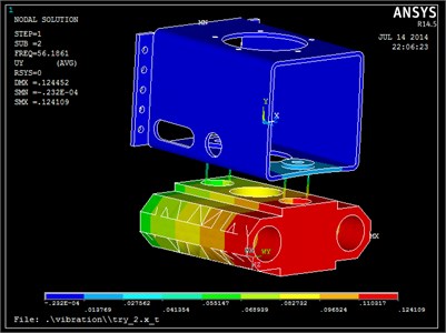
The simulation results are shown in Fig. 7. (1) The first three vibration frequencies are 15.71 Hz, 56.19 Hz and 67.40 Hz respectively, which are within the operating frequency of the vibrating body. The greatest vibration frequency can be used in drilling. (2) Because there are differences on both sides of vibration isolation system, one end of the vibrating body -direction displacement is maximum while minimum on the other end when the first-order resonance occurs. (3) Vibration are presented in , and directions, but has the main vibration. (4) The fourth-order oscillation mode is mainly caused by vibration of the support housing, whereby vibration of the support body for increasing stiffness can be avoided or reduced. (5) Vibration system mainly occurs on the vibrating body, and the support frame vibration is tiny.
Fig. 7Form four-order vibration modes of the vibration head
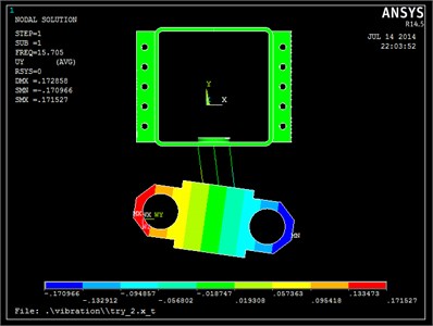
a) First vibration mode
b) Second-order model
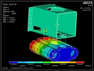
c) Third-order model
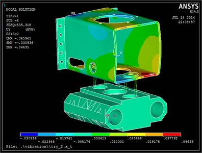
d) Fourth-order model
4. Test of the vibration head
The results of finite element simulation show that the maximum vibration force reaches up to 18 tons, which has met the design requirement. The resonance is likely to occur near the natural frequency, which can be fully used in the field work. At the same time, the anticipated force of the isolator has been improved, reducing the difference between the two isolation structures. Based on this, the physical prototype is developed to test the vibration.
4.1. Experiment methods
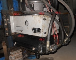
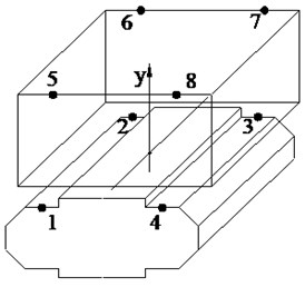
The operational modal analysis (OMA) is used to control system of the hydraulic motor driven eccentric rotation. An accelerometer is used as a vibration sensor. In the working conditions, many key points of the acceleration signal are measured. The FFT spectrum analysis and modal parameter identification are used to get the natural frequency, vibration damping ratio, and other parameters of the structure. The results of the vibration analysis provide a good reference for subsequent structural optimization. There are four key measurement points on each plane vibrating body and bracket arrangement. There are a total of eight points, each of which is measured in the same direction.
Fig. 8Layout diagram of the measuring points
In the process of the acoustic vibration drill, it has three phases: starting, periodic vibration, and stopping. Among them, the starting and stopping phases are both transitional. During the smooth operation phase, the exciting force is characterized by periodicity. The flow rate of the hydraulic motor is adjusted by changing size of the valve port, causing the change of exciting force. The vibration test is made by changing the excitation forces under different speed. Compared support acceleration with vibrating body, the vibration characteristics of the vibrating body is identified. Research isolation effect and the modal analysis are also carried out.
Fig. 9Time domain signal during sonic drilling
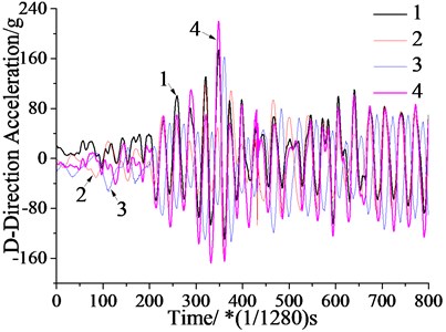
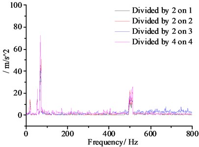
Fig. 10Signal time-frequency distribution
4.2. Vibration signal analysis
Fig. 9 shows measuring point 1, 2, and vibration signal measuring points 3 and 4. The vibration is characterized by the superimposition of different periodic signals. The vibration amplitude of measuring point 1 and measuring point 4 is slightly larger than points 2 and 3, which agrees with the results obtained from stimulation.
Fig. 10 is a spectrum diagram of measuring point 1, the measuring point 2, time-domain signal measuring point 3 and the measuring point 4 by FFT analysis. From the Fig. 9, the first, second, third and fourth natural frequencies are 14.8 Hz, 57 Hz, 69 Hz and 510 Hz respectively. The experimental results are consistent with the simulation ones. The simulation results are proved to be correct. It also proves that when the vibration frequency is 57-69 Hz, it will generate resonance. Also, when the frequency is 150-200 Hz, there will be no resonance generated.
5. Conclusion
1) The virtual prototyping technology is used to dynamic design the audio head vibration. The results are amended on the basis the method of modal analysis, which has a convenient, high design quality and short development cycle characteristics.
2) Design of the main vibration of the vibration energy is concentrated in the longitudinal direction of the head. The maximum excitation force of the designed vibration head reaches 18 tons, achieving the expected goal.
3) The natural frequency of vibration of the head is concentrated in the vicinity of 14.8 Hz, 57 Hz and 69 Hz, around which the vibration energy can be obtained using resonance. When the frequency of vibration reaches the maximum, the resonance will not occur, ensuring the vibration head’s security.
References
-
Reece Ray Good vibes: sonic drilling excels in tailings applications. E&MJ-Engineering and Mining Journal, Vol. 211, Issue 1, 2010, p. 73-73.
-
Wu G. L. The development of sonic drilling technology and its applications. Exploration Engineering (Drilling and Tunneling), Vol. 31, Issue 3, 2004, p. 39-41.
-
Xiong Y. C. The Research on the Mechanism of the Sonic Drilling Technology. China University of Geosciences – China University of Geosciences for Master Degree, BeiJing, 2007, p. 8-25.
-
Burlingame Michael J., Egin Dincer Armstrong William B. Unit weight determination of landfill waste using sonic drilling methods. Journal of Geotechnical and Geoenvironmental Engineering, Vol. 133, Issue 5, 2007, p. 609-612.
-
Oothoudt T. The benefits of sonic core drilling to the mining industry. 6th International Conference on Tailing and Mine Waste, Vol. 99, 1999, p. 3-8.
-
Boart longyear crew sets sonic drilling depth record at Bingham canyon. E&MJ-Engineering and Mining Journal, Vol. 213, Issue 11, 2012, p. 120-122.
-
Zhang P. F., Jia S. K., Zhu W. J. Development of TGSD-50 sonic drilling coring rig. Exploration Engineering (Rock and Soil Drilling and Tunneling), Vol. 38, Issue 1, 2011, p. 35-38.
-
Dupac Mihai A virtual prototype of a constrained extensible crank mechanism: dynamic simulation and design. Proceedings of the Institution of Mechanical Engineerings Part K – Journal of Multi-body Dynamics, Vol. 227, Issue 3, 2013, p. 201-210.
-
Tornincasa S., Bonisoli E., Di Monaco F. Virtual prototyping through multisoftware integration for energy harvester design. Journal of Intelligent Material Systems and Structures, Vol. 25, Issue 14, 2014, p. 1705-1714.
-
Ciszewski M., Buratowski T., Giergiel M. Virtual prototyping design and analysis of an in-pipe inspection mobile robot. Journal of Theoretical and Applied Mechanics, Vol. 52, Issue 2, 2014, p. 417-429.
-
Nehaoua L., Djemai M., Pudlo P. Virtual prototyping of an electric power steering simulator, IEEE Transactions on Intelligent Transportation System, Vol. 14, Issue 1, 2013, p. 274-283.
-
Nancy Argyle The origins of sonic. GeoDrilling International, Vol. 128, Issue 1, 2006, p. 17.
-
Li Z. Y., Lu Z. R. Research on combined stiffness characteristic of metal rubber damper. Journal of Harbin Institute of Technology, Vol. 37, Issue 4, 2005, p. 1327-1332.
-
Zhao C. S., Zhu S. J. Study on the static stiffness characteristics of rubber-mental ring. China Mechanical Engineering, Vol. 15, Issue 3, 2004, p. 962-967.
-
Maly J. R., Bender K. A., PendletonS. C. Complex stiffness measurement of vibration damped structural elements. 18th International Modal Analysis Conference, 2000, p. 391-397.
About this article
This work is supported by National Natural Science Foundation of China (No. 51004086), the Fundamental Research Funds for the Central Universities (No. 2652015059, 2652015061), the Beijing Higher Education Young Elite Teacher Project (Grant No. YETP0645) and Beijing Organization Department Outstanding Talented Person Project (No. 2013D009015000002). Meanwhile, great thanks also go to former researchers for their excellent works, which give great help for our academic study.
