Abstract
The dynamic explicit finite element program LS-DYNA was used to simulate the nuclear power plant shock and impact crashed by the aircraft. Through the simulation of reinforced concrete slabs hit by the engine, constitutive models used in the simulation were verified. The grid size effect of the finite element model was studied. Using the result of the simulation, characteristics of impacting load were analyzed.
1. Introduction
At the end of 2011, 15 nuclear power plants have been built, 26 units under construction, and 21 units planned[1]. In the same time, with the rapid development of nuclear power, the safety of nuclear power is also receiving increasing attention. Considering the particularity of the nuclear power plants and the serious consequence of the fuel leak, it is necessary to get more attentions with the safety of the nuclear power plants, particularly in some extreme cases (such as fires, earthquakes, tsunamis and aircraft impact, etc.) [2].
The 911 event in 2001 prompted the public to pay more attention on the large commercial aircrafts impact at the important structures. With the nuclear power plants development and the amount of large commercial aircrafts sharp increase, the problems of large commercial aircrafts impact nuclear power plant has also attracted the attention of public. Thus, the plane impacts the shield building has been an important consideration in the layout of nuclear power plant [3].
The analysis of plane impact nuclear power plant can use the finite element model directly. This calculation need to establish the structure model of nuclear power plant, and a complicated nonlinear aircraft model. Beyond these, since this process involves contact relationship and dynamical response between the aircraft and nuclear power plant, it would be a complex operation. It’s generally desirous to get the time-travel curve of impact load of the aircraft in engineering design, and apply these curves to analysis the impact effect, this method is convenient and practical. However, current research on aircraft impact loads in China is still relatively few [4, 5].
Here, we report the impact process between aircraft and shielding building of nuclear power plants in nonlinear finite element model with ANSYS/LS-DYNA. And the nonlinear, large deformation, dynamic contact and other factors have been considering. The constitutive relations and parameters of material are validated by the experiments of engine impacting the reinforced concrete plate, and the mesh size effect was also analyzed. A large commercial aircraft at 200 m/s impacting on steel concrete nuclear power plant structure is discussed, and clarified the discipline of deformation and destruction of the nuclear power plants. The analysis and comparison of time-travel curve of nuclear power plants generated at the hypothesis of constitutive model of the linear elasticity and rigidity. The results show that the nuclear power plant stiffness relative larger than aircraft, thus, the method proposed by Riera [6] can be used to determine the impact force time-curve of loading. But, it could not provide the load distributions by using Riera method. We recommended the load uniformly distributed on the fuselage surface, but the result of this distribution differ greatly from the real situation. The results of time-travel curve and distributions obtained in this paper have practical reference value in service to the design of nuclear power plants.
2. Material constitutive model
When the large commercial aircraft impacts on the shielding building of nuclear power plants, the action time is short, the peak is high, and the strain rate also is high. There is a vast difference in the mechanical properties of materials between the impact and the static load. So it is critical to ensure constitutive ralaitons of the materials.
Large commercial aircraft is mainly made of aluminum alloy and steel. And the materials of shielding building of nuclear power plants are steel and concrete. This section we will analysis the material constitutive model and parameters of aluminum alloy, steel and concrete.
2.1. Constitutive relations of steel and aluminum alloy
Effect of rate of metallic material in the collision condition is very obvious whether in the aircraft or the nuclear power plants, so we chose the Cowper-Symonds [7] model which considering the yield, strengthen and rate effect. The model is metal collision constitutive that be regularly used in analysis of impact, the function can be expressed by Eq. (1):
where, – the yield stress which considering the rate effect. – the initial yield stress; – the strain effect. – the effective plastic strain. – the plastic hardening modulus, , – the initial elastic modulus. – plastic tangential modulus. – adjust the isotropic hardening and the aerodynamic of hardening parameters. is isotropic hardening. , is the aerodynamic of hardening. , – constants of Cowper-Symonds relation.
2.2. Constitutive relations of concrete
Due to the concrete is the main stress material in nuclear power station, so, it is necessary to study the nonlinear constitutive relation and damage mechanism of concrete, and considering the strain effect. HJC [8], Brittle_Damage [9] and Concrete_Damage today are primarily used to dynamic analysis of concrete. Here, we choose Concrete_Damage to simulate the material constitutive model of concrete. Cooperation of concrete and steel, strain rate effects, damage effects, strain hardening and softening are included.
Concrete_Damage constitutive [10] is a specialized model of concrete that assists to analyze the problems of explosion and impact. The model defines three independent strength surfaces:
where, is (Initial yield surface), (Ultimate strength surface), (Residual strength surface) respectively; , hydrostatic pressure, define and volumetric strain by equation of state; ( 0, 1, 2) – constants identified through experiments.
Subsequent yield surface can be obtained from the parameter by linear interpolation method. Parameter reflects the hardening and softening of yield surface, is a function related to accumulate effective plastic strain, ranging between 0 and 1. When reach the initial yield surface but not reach the ultimate strength surface, calculating the subsequent yield surfaces with interpolation method by Eq. (3), at this moment, change from 0 to 1, began to soften after reaching the ultimate strength surface, calculating the subsequent yield surfaces by Eq. (4), change from 0 to 1 correspondingly:
There are many parameters in this model, a large number of experiments are necessary to establish these parameters, here, parameter values references are identified in Ref. [11] and [7].
2.3. Verify material model and parameters
2.3.1. Verification tests
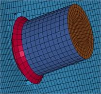
A series of experiments of simplified engine at 100 m/s, 150 m/s and 215 m/s respectively impact on the square reinforced concrete slabs in Ref. [12], with the square plate of side length 1.5 m, thickness 12 cm, percentage of longitudinal reinforcement is 0.4 %, spacing of 60 mm, diameter of 6 mm, no stirrups. The engine model in experiments is shown in the Fig. 1. The total weight is 3.5 kg. This paper intends to use these experiments to verify the constitutive and related parameters of concrete and steel.
Fig. 1Engine model in experiments
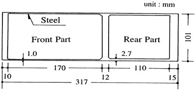
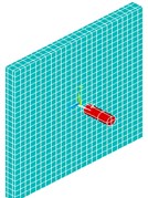
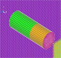
Fig. 2Finite element model of slab and engine
The experimental results show that cylinder crushing strength of the concrete (2300 kg/m3) is 23.5 MPa, yield strength and elastic modulus of longitudinal reinforcement are 447.2 MPa, 2.05×10⁵ MPa, yield strength and elastic modulus of steel of the engine are 411.9 MPa, 2.14×10⁵ MPa respectively. The constitutive behavior of the concrete in the finite element model is modeled with CONCRETE_DAMAGE, recommended curve decided by the results of many experiments in LS-DYNA is used as the curve of rate effect in the constitutive relations [7]. Full details of the elastic-plastic material parameters used for the steel can be found in Table 1. In order to simulation failure of concrete material, we using EROSION algorithm here. The EROSION algorithm can control unit failure through the definition of stress threshold or strain threshold, and the thresholds must be according to the calculation results and the test results. Because the concrete stress changes and constitutive curve is descending, the maximum principal strain was selected to control the unit failure. Here, we choose 0.17 of the maximum failure principal strain by pre-computation.
The Fig. 2 shows a finite element model of slab and engine. Concrete using Solid 164 discrete, the unit size of 30 mm. Rebar uses Link 160 discrete with rod element, the unit size of 30 mm. The concrete and rebar are using joint to simulation. The steel of engine uses Shell 163 discrete, the unit size of 10 mm. There are 285872 model-cell in total. The reinforced concrete plate impacts on the four corners of the back, the clamped constraint in the range of 200×200 mm.
The penalty function method is applied for finding the contact interface to simulate the engine impacts on the reinforced-concrete slab. According to the extent of penetration of interdependent node of master-slave interface, interface contact force that is in proportion to depth of penetration and stiffness is introduced to ensure penetrate the contact interface does not happen.
The finite element model of engine and reinforced concrete slab are established, defines the type of contact of engine and reinforcement which in reinforced concrete slab and concrete subsequently. The engine and reinforced contact with automatic point surface contact algorithm. Contact between the engine and the concrete using the automatic surface to surface contact algorithm. Penalty function adjust on the actual penetrativity. The coefficient of friction is determined according to the actual contact surface. In this paper, the penalty factor is 1.0, and the coefficient of friction use the default value.
Table 1Material parameters of steel plates and rebar
Item | Steel sheet | Rebar |
Density (kg/m3) | 7.8×10³ | 7.8×10³ |
Elastic modulus (MPa) | 2.14×10⁵ | 2.05×10⁵ |
Poisson ratio | 0.3 | 0.3 |
Yield strength (MPa) | 412 | 447 |
Tangent modulus (MPa) | 5×10³ | 8.5×10³ |
0 | 0 | |
5 | 5 | |
40 | 40 | |
Failure equivalent plastic strain | 0.8 | 0.12 |
2.3.2. Experiment and numerical simulation analysis
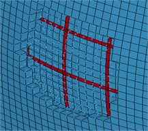
In addition to match the damage modes, a quantitative comparison was made at different velocities. The front surface cratered with the engine traveling with a velocity 100 m/s, impacts on the concrete, no breaking on back side, and this result was similar to the result of experiment (Fig. 3). When the velocity of engine raised to 150 m/s, concrete surface defect and the crater formation and, longitudinal reinforcement exposed on the back side (Fig. 4).
When the velocity of engine is 215 m/s, reinforcement fractured, concrete damaged, and concrete penetrated (Fig. 5). In numerical simulation, the residual velocity is 52 m/s, much closer to the experimental value (55 m/s). The shape of crater is also consistent with experiments.
Fig. 3Engine impacts on concrete slab with 100 m/s

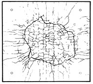
Fig. 4Engine impacts on concrete slab with 150 m/s
The comparison of the experiment and numerical simulation results is the Table 2. The results show that the reinforced concrete plate failure types and failure pattern is consistent with the experimental. The results also show the simulation model is reasonable and the parameters are reasonable.
Fig. 5Engine impacts on concrete slab with 215 m/s
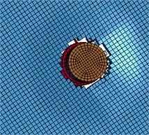
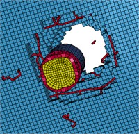
Table 2Comparison of the exp. and num. simulation results
Velocity (m/s) | Results of exp. | Results of num.simulation | Notes |
100 | cleave | cleave | front side: spallation |
150 | scabbing | scabbing | back side: fragments |
215 | penetrate | penetrate | residual velocity error: 5 % |
3. Models of the nuclear power plants and aircraft
3.1. Nuclear power plants model
The shielding building model was established based on one type of nuclear power plant and combined the commonly nuclear power plant size that used in international.
The external radius of tube structure is 22 m, and the height is 44 m, the top of structure is a hemisphere with a radius of 22 m. Shielding building consists of concrete of 1 m thick inside and both sides with 13 mm steel plates. The total height is 66 m. Concrete uses Solid 164 discrete, and the steel plate uses Shell 163. Considering the final cost, the length of a side is 25 cm, the number of total units is 1018368, and the physical unit is 678912.
Considering practical reality of shielding buildings of nuclear power plant, we deem that steel and concrete has reliable connectivity. Here, we use common node and neglect the slip between them, and the bottom of structure with fixed boundary conditions.
The relation of CONCRETE_DAMAGE is used as constitutive behavior of concrete and the steel plate is modeled with the Cowper-Symonds, the compressive strength of concrete is 48 MPa, and the other parameters the same as stated above or before.
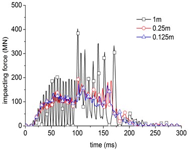
Fig. 6Influence of the mesh size on impacting force
3.2. Aircraft model
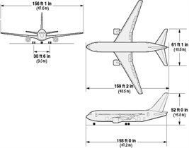
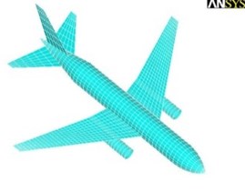
The key control quantities of aircraft model are total mass, engine mass and mass distribution. Generally speaking, the aircraft we selected should be able cover the weight and quantity of the most commercial airplane [13]. Due to the difficulty of obtaining the accurate data of aircraft structure, in this paper, we selected the size and weight of large commercial aircraft Boeing 767-200ER as a reference [14]. It is about 80 t in weight, which includes 10 t of engine. It is about 48.5 m in length. Add the plate and clapboard to achieve the real effect-simulating of engine. Aircraft uses shell elements, because the EROSION algorithm used to remove the unit in the condition of unit failure, the mesh size will make a strong effect on impact results, so, we analysis the impact force with the different mesh size. Fig. 6 shows the influence of the different mesh size on impacting force, it will stable with the decrease of mesh size. In this paper, we choose 0.25 m of mesh size, the total unit is 9148. The aircraft size and finite element model as is shown in Fig. 7.
Fig. 7Dimensions and finite element model of the aircraft
4. The simulation of aircraft impact on nuclear power plant
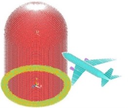
It is concerned not merely with the velocity of impact, but with its position and angle to simulate the aircraft impacting the shielding building of nuclear power plant. The most unfavorable impact position is the junction of cylinder and the hemisphere, and the most unfavorable act is vertical impact [15]. In this paper, we simulate the aircraft vertical impact the junction of cylinder and the hemisphere of the shielding building at the velocity of 200 m/s.
Fig. 8The aircraft hit nuclear power plant
We use the finite element model which referred in the section 2, the total units are 1027516. We defined the contact is automatic contact of surface to surface, the penalty function coefficient is 1.0. Additional details of the model are given in section 2. We consider the impact act, ignoring the burn and explosion of fuel.
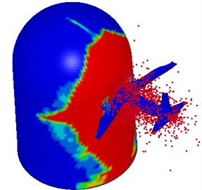
Fig. 9-Fig. 13 show the impact process. The impact process is as follows: at the time 0 s, the head part of the airplane to the shield building surface is 3 m, as shown in Fig. 9. At the time 0.051 s, the engine starts to hit the shield building surface. The concrete structure has been damaged by the engine and aircraft body as shown in Fig. 10. At the time 0.13 s, the engine has collisions to the shield building completely, as shown in Fig. 12. At the time 0.22 s, the aircraft has crashed into the hole caused by the impact, as shown in Fig. 13. At the end of the impact process, the result was observed that the impact part of aircraft body has been destroyed completely, as shown in Fig. 14. A significant deformation of the impacted position of nuclear power plant occurs. The destruction of the concrete for the reason of the impact of engine and fuselage, and small deformation occurs in other regions, as shown in Figs. 15-16.
Fig. 9The impact process at t= 0 s
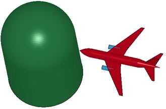
Fig. 10The impact process at t= 0.051 s
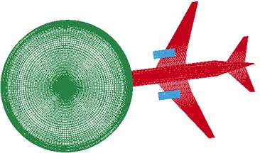
Fig. 11The impact process at t= 0.0105 s
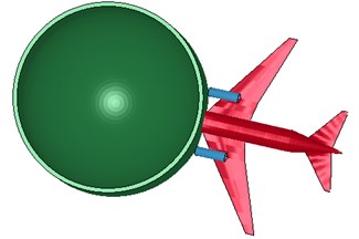
Fig. 12The impact process at t= 0.13 s

Fig. 13The impact process at t= 0.22 s
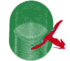
Fig. 14The damage of aircraft
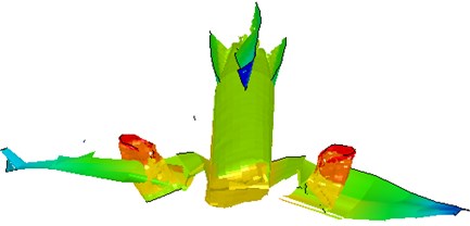
Fig. 15Displacement nephogram of nuclear power plant
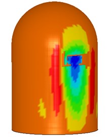
Fig. 16Strain nephogram of nuclear power plant
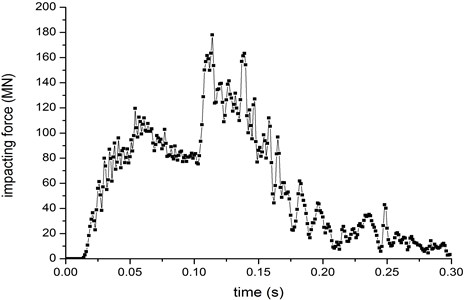
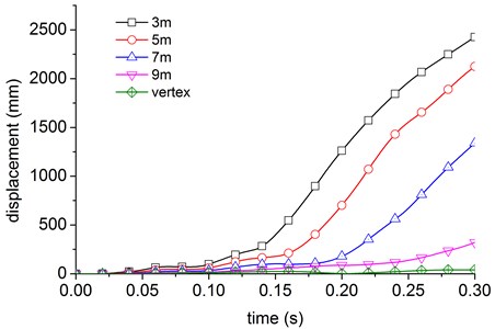
The displacement curve of the positions of 3 m, 5 m, 7 m, 9 m above the collision center and the vertex of the nuclear power plant is shown in Fig. 17. The simulation results indicated that the influence decreased with the distance from the impact point. The maximum displacement at the top of nuclear power plant is just 15 mm. The velocity of undamaged part of fuselage is shown in Fig. 18. The impacting load of aircraft is shown in Fig. 19, the maximum impact force together about 170 MN.
Fig. 17Displacement curve of nuclear power plant
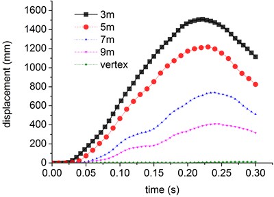
Fig. 18The velocity of the aircraft
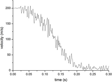
Fig. 19The impacting load of aircraft
Different kinetic energies of the aircraft should result into different damage severity. We wonder the relationship between the damage to the wall and the velocity of the aircraft. The impact velocity of aircraft is 200 m/s, 150 m/s and 100 m/s respectively, according to the different impact velocity. The impact position is the same as above. The time history curve of impact loads is obtained as shown in Fig. 20. The velocity curve of aircraft, part of not destroyed, is as shown in Fig. 21. Although the initial impacting velocity is different, but the time of the velocity reduced to zero is nearly the same.
The results show the impacting force decreases as the velocity decreases. The shield building structure is intact under the impacting velocity of 150 m/s. The largest displacement of center point is about 1200 mm. The aircraft engine arrives to the nuclear power station at the time 0.165 s. And the velocity has been relatively small (about 50 m/s). The peak displacement value caused by engine is not very high. The displacement curve of the positions of 3 m, 5 m, 7 m, 9 m above the collision center and the vertex of the nuclear power plant is shown in Fig. 22. Compared with the 200 m/s impacting velocity result, the displacement greatly reduces. It decreases rapidly as distance from the impacting center increases.
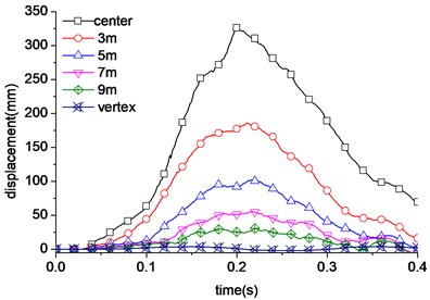
The shield building structure is also intact under the impacting velocity of 100 m/s. The largest displacement of center point is only about 350 mm. As for the smaller impacting velocity, the aircraft velocity has reduced to zero when the distance is 13 m to the aircraft head. The peak value of impacting load caused by the engine does not appear. The engine doesn’t hit the shield building. The displacement curve of the positions of 3 m, 5 m, 7 m, 9 m above the collision center and the vertex of the nuclear power plant is shown in Fig. 23. Compared with the 150 m/s impacting velocity result, the displacement also greatly reduces.
Fig. 20Impacting force under different velocity
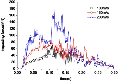
Fig. 21Different time history of the not destroyed part velocity reduced to zero
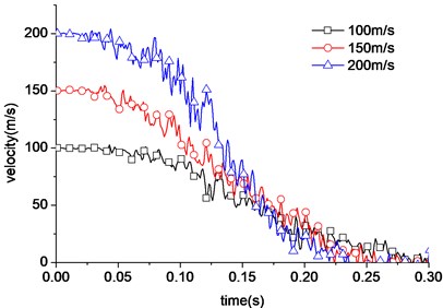
Fig. 22Displacement curve of nuclear power plant under 150 m/s
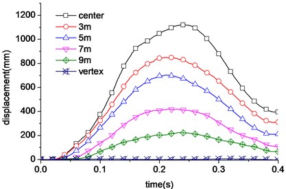
Fig. 23Displacement curve of nuclear power plant under 100 m/s
Above all, the displacement greatly reduces as the impacting aircraft velocity reduces. The impacting load increases rapidly under the velocity 200 m/s. The engine hits the shield building. But when the impacting velocity is 100 m/s, the engine doesn’t reach shield building surface. It’s obvious that the impacting velocity has great influence to the impacting loading. The shield building is not destroyed under the impacting velocity 100 m/s and 150 m/s.
5. Analysis and discussion of impact loads
There are a range of variables of influencing aircraft impact force, such as the weight of aircraft, the mass distribution and the materials, the size of the shielding building, the materials, velocity of aircraft and so on.
For further analysis of the impact loads, the curve of impact loads with nonlinear model of aircraft impacts the nuclear power plant with a rigid or linear elastic model respectively, as is shown in Fig. 24. All the three kinds are close in the action time, tendency and the peak value. These show that nuclear power plants is stiffer than aircraft, so can compute the summations of forces on the basis of taking the nuclear power plants as rigid or elastic body.
Due to the stiffness of nuclear power station is relatively larger than aircraft, the Riera [6] method can be used to analysis the time curve of the impact force. The Riera method makes two assumptions: (i) the target is rigid and the impact orientation is normal to the target, (ii) the aircraft is one-dimensional structure along its length, so the aircraft fuselage will progressively crush/buckle axially. The impact force is given by Eq. (5):
where, is the impact force, is the distance measured from the nose of the aircraft to the current location, is the pressure of crushing at the position of the aircraft fuselage, is the mass per unit length of the aircraft. We also calculated the impact force at the velocity of 200 m/s by the method of Riera. The results of this calculation are shown in Fig. 25.
Fig. 24The impact force obtained by different models
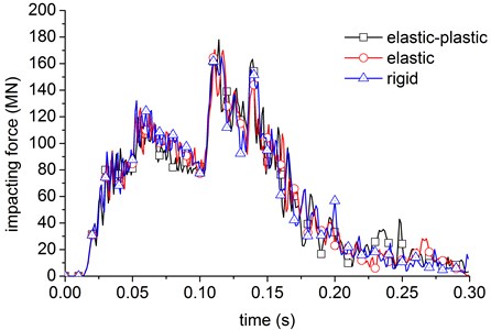
Fig. 25The impact force curve obtained by rigid’s method
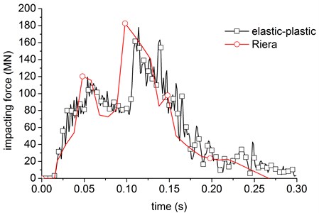
The result shows that time-travel curves of summations of impact forces with the method of Riera are agree with the elastic-plastic method except the second peak. Thus making the Riera method better used to calculation the impact force. But the Riera method does not give the distribution form of impact loads, in general, it will make load distribution to the aircraft in the area, the load on the nuclear power plant according to uniform distribution. The result shows that the edge of concrete would be destroyed firstly according to the loading method, but big difference in the damage modes and reason with the simulation of the aircraft impact the nonlinear model of nuclear power plant.
The displacement curve of the positions of 3 m, 5 m, 7 m, 9 m above the centroid and the vertex of the nuclear power plant with the method of continuous load is shown in Fig. 26. Compare with the Fig. 17, it shows that they have a great difference in the displacement and the whole response. All of these shows we need to consider each load and distribution separately, not simply is a uniformly distributed load on the body function area.
Fig. 26Displacement of structure by uniform loads
6. Conclusions and prospects
The CONCRETE_DAMAGE and Cowper-Symonds constitutive relations that from the experiment of engine impact on reinforced concrete slab can be good apply to the simulation of the property of the concrete and metal materials. And the contact algorithm and related parameters have been discussed and made sure. By the analysis of using different mesh sizes of aircraft impact on the rigid body, reasonable mesh size of the model of aircraft is determined.
We report the nonlinear dynamic analysis of large commercial aircraft at a velocity of 200 m/s impact on steel concrete of nuclear power plant. The results show nuclear power plants deformed significantly, which due to the impact of fuselage and engine, while small deformation occurs in other positions, the maximum impact force together about 170 MN.
Preliminary contrast analysis of the time curve of impact force of nuclear power plant using elastic-plastic model and the impact load of nuclear power plant using rigidity and linear elastic body, the numerical results show that, the pattern of the curves is similar for the three cases and greater rigidity of nuclear power plants. So the impact force generated by aircraft can be computed from the Nuclear power plants assumed as an elastomer or a rigid body, thus Riera method can be used to derive the total load of the impact force-time curve. However, this method could not determine the distribution of the load. There are large differences in the result of uniform body surface loading and nonlinear model. Therefore, the load distribution needs further study.
Space forbids, we primarily analyze the laws of shock and impact loads of large commercial aircraft impact on nuclear power plants. Dynamic response of nuclear power plant and the distribution of impact forces will be discussed in elsewhere.
References
-
Zhao Xiaohui, Zou Shuliang, Liu Yong Analysis of inland nuclear power development situation. Journal of University of South China, Vol. 13, Issue 3, 2012, p. 1-7.
-
Wang Yulan Research progress of security performance of nuclear power plant suffering external events. Power System and Clean Energy, Vol. 25, Issue 10, 2009, p. 74-77.
-
Tang Bo Requirements for nuclear power plants against large commercial aircraft impact. Nuclear Safety, Vol. 3, 2010, p. 1-16.
-
Zuo Jiahong Nonlinear analysis of Qinshan nuclear power plant containment under impacting of the aircraft. Nuclear Science and Engineering, Vol. 12, Issue 1, 1992, p. 35-42.
-
Wang Yuangong, Yu Aiping The determination of the load of the aircraft hitting the reactor containment. Nuclear Science and Engineering, Vol. 11, Issue 3, 1991, p. 208-215.
-
Riera J. D. On the stress analysis of structures subjected to aircraft impact forces. Nuclear Engineering and Design, Vol. 8, Issue 4, 1968, p. 415-426.
-
LS-DYNA Keyword User’s Manual. Version 971, 2007.
-
Holmquist T. J., Johnson G. R. A computational constitutive model for concrete subjected to large strains, high strain rates, and high pressures. Proceedings of the 14th International Symposium on Ballistic, Quebec, Canada, 1993.
-
Govindjee S., Kay G. J., Simo J. C. Anisotropic modelling and numerical simulation of brittle damage in concrete. International Journal for Numerical Methods in Engineering, Vol. 38, Issue 21, p. 3611-3633.
-
Malvar L. J., Crawford J. E., Wesevich J. W., et al. A Plasticity concrete material model for DYNA3D. International Journal of Impact Engineering, Vol. 19, Issues 9-10, 1997, p. 847-873.
-
Crawford J. E., Magallanes J. M., Lan S., Wu Y. User’s manual and documentation for release III of the K&C concrete material model in LS-DYNA. TR-11-36-1 Technical Report, Karagozian & Case, Burbank, CA, 2011.
-
Muto K., Tackihawa H., Sugano T., Tsupota H., et al. Experimental studies on local damage of reinforced concrete structures by the impact of deformable missiles, Part 1: Outline of test program and small-scale tests SmiRT 10. American Association for Structural Mechanics in Nuclear Reactors, Los Angeles, California, 1989.
-
EPRI, Deterring Terrorism: Aircraft Crash Impact Analyses Demonstrate Nuclear Power Plant’s Structural Strength. Electric Power Research Institute, America, 2002.
-
Boeing Commercial Airplanes. http://www.boeing.com.
-
Prabhakar G., Ranjan R., Mini K. Paul, et al. Analyses of aircraft impact on containment structure. 5th Asia-Pacific Conference on Shock and Impact Loads on Structures, Changsha, China, 2003, p. 315-333.
About this article
The authors would like to acknowledge the financial support from National Natural Science Foundation of China under Grant number 51308019, Project supported by Beijing Postdoctoral Research Foundation and Beijing Municipal Natural Science Foundation (8144039) for carrying out this research.
