Abstract
To investigate the mechanical behavior and load torque of the cutting head in the rock fragmentation process, a numerical model was developed based on fracture mechanics and finite element method. And then, rock fragmentation and factors influencing the force of cutting head were investigated. The good agreement of variation characteristics of cutting torque between experimental results and numerical values indicated that the numerical model was reliable and correct, and thus it could be a useful approach for simulating rock fragmentation. The cutting torque and its range of fluctuation increased with the feeding speed, but decreased with the slope of linear variation of slanting angle (SLVSA). Improving the rotation speed could reduce cutting torque, but its effect on torque fluctuation was inconspicuous. Regression equations between the characteristic index (CI) of cutting torque, feeding speed, rotation speed and SLVSA are given.
1. Introduction
The roadheader, a key item of equipment for underground excavation, is widely used in rock fragmentation. The cutting head is the cutting mechanism of a roadheader, and its capacity directly influences the working performance and lifespan of the roadheader [1, 2]. Hence, the accurate prediction of cutting torque has an important significance for the design of cutting head and roadheader. As a conquence, many researchers have attempted to predicate the pick cutting force by means of experimental, theoretical, and numerical methods, and have use the predicated pick cutting force to provide some basis for cutting head design. On the basis of data from various rock-cutting experiments using a conical pick, the relationships between pick cutting force and rock compressive strength, tensile strength, dynamic and static modulus of elasticity, and brittle index have been published [3-6]. Tiryaki et al. [7] adopted multiple linear and non-linear regression, a regression tree model, and a neural networks method to set up empirical formulas for predicting the peak cutting force of concial pick. Several theoretical models have been developed to describe the relationships between the peak cutting force and cutting parameters such as cutting depth, cutting angle, rock properties, pick shape, and so on [8-12]. Several numerical methods have been introduced to reappear the rock cutting process for predicating pick cutting force, such as the finite element method and the discrete element method [13-18]. However, use of the pick cutting force to design or study cutting head possesses some limitations, such as cutting head performance and vibration characteristics. To overcome the difficulties of coal fragmentation experiments in underground coalmine, Liu et al. [19] used the similarity experiment method to investigate rock fragmentation by shearer drum under different cutting conditions, and the relationships between torque, specificenergy consumption, and cutting parameters were given. However, similarity experiments require a considerable manpower resources and cost. In recent years, several numerical methods have been introduced to model rock fragmentation by cutting mechanisms. Based on elastic material and the shear failure criterion, Yu et al. [20, 21] used the finite element method to investigate coal fragmentation by a continuous miner, and their experimental and numerical results showed good agreement. Li et al. used the finite element method to simulate rock fragmentation under transverse cutting of a roadheader, and investigate the effect of rock strength on cutting forces [22]. So far, the above researches have promoted the development of the design of pick and cutting head to some extend, but numerical study of rock fragmentation by the cutting head of a roadheader is incomplete.
In this research, a numerical model of rock fragmentation by the cutting head of a roadheader was developed based on fracture mechanics and the finite element method. The correctness and reliability of the numerical model were verified through experimental results, and then the effects of feeding speed, rotation speed and SLVSA on rock fragmentation were investigated.
2. Numerical model of rock fragmentation by cutting head
2.1. Constitutive model of rock
The brittle cracking model was adopted to describe rock macroscopic mechanical characteristics in the numerical model of rock fragmentation by a cutting head, which could simulate the failure and fracture behavior of brittle materials in tension, shear, or combined tension and shear, such as concrete decomposition or rock fragmentation [23]. The continuum element method was applied to the mechanical characteristics of brittle or quasi-brittle materials in the cracking constitutive model. That method does not track individual “macro” cracks, so constitutive calculations were performed independently at each material point. The presence of cracks was entered into these calculations by the way in which the cracks affected the stress and material stiffness associated with the material point. A simple Rankine criterion was used to detect crack initiation. This criterion stated that a crack formed when the maximum principal tensile stress exceeded the tensile strength of the brittle material. As soon as the Rankine criterion for crack formation was met, we assumed that a first crack has formed. The crack surface was taken to be normal to the direction of the maximum tensile principal stress. Fig. 1(a) shows the crack model based on mode I fracture, and Fig. 1(b) shows the change in material tension stress with crack length. An important feature of the cracking model was that, whereas the crack initiation was only based on Mode I fracture, the post-cracked behavior included Mode II as well as Mode I. Therefore, a shear retention model was adopted to describe crack shear behavior in which the post-cracked shear stiffness was defined as a function of the opening strain across the crack.
Fig. 1Brittle cracking model
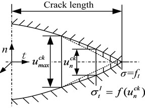
a) Mode I fracture of crack
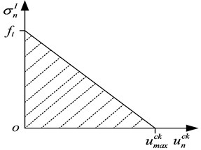
b) Tension stress-crack length
For mode I fracture in the direction, the crack tension stress could be described as:
When cracks form, the material shear modulus could be expressed as:
where is the crack tension stress; is the tensile softening evolution function; is the opened displacement of a crack; is the opened strain of crack; is the characteristic length relevant to the finite element; is the maximum opened displacement of the crack; is the maximum opened strain of the crack; is the function of shear retention; is the shear modulus relevant to the opened strain of the crack; is the material shear modulus; and is a parameter related to the function of shear retention. According to the mechanical properties of different brittle materials, the parameter could be a natural number, and is equaled to 2 in the numerical model for rock.
To reproduce rock fragmentation by the cutting head of a roadheader actually, the failure criterion of the rock for direction was defined as:
where is the failure strain of a crack; is the failure displacement of the crack. The failure strain and displacement are related to the characteristic length of finite elements; is equal to 0.2 mm in the model developed.
When the opened displacement or strain of a crack satisfied Eq. (5), the integral points failed, and all their stress components would be equal to zero. When all integral points of an element failed, the element was considered as failure, and it was removed to reappear the rock fragmentation.
2.2. Dynamic contact boundary
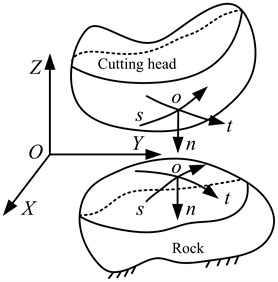
A continuous state (CS), a sliding friction state (SFS) and a separated state (SS) could exist between cutting head and rock, and they occurred alternately in rock fragmentation by the cutting head of the roadheader. For the longitudinal contact problem, the contact state between cutting head and rock was obtained from iterative computation with a hybrid algorithm of the finite element method, and the contact state changed with time [24, 25]. For iterative computation at every moment, the convergence criterion required that the contact states of two iterations be consistent. The dynamic contact system is shown in Fig. 2, and there are two coordinate systems such as global coordinate system (-) and local coordinate system (-). The local coordinate system consists of the outward normal direction () at the contact point, tangential directions ( and ) of the principal curvature of the surface perpendicular to the outward normal direction ().
Fig. 2Global and local coordinate system
Therefore, the variation of contact state could be determined according to the displacement and contact force between cutting head and rock:
where , , were the contact force components in the , , and directions of the local coordinate system of the cutting head, respectively; , , were the contact force components the , , and directions of the local coordinate system of the rock, respectively;, , were the displacement components in the , , and directions of the local coordinate system of the cutting head, respectively; , , were the displacement components in the , , and directions of the local coordinate system of the rock, respectively; , , were the relative gap components in the , , and directions of the local coordinate system between cutting head and rock, respectively; was the relative friction coefficient; was the angle of the relative sliding direction and was the direction of the local coordinate system.
2.3. Geometric model of rock fragmentation by cutting head
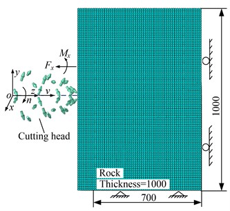
The numerical model consisted of the geometric model establishment, definitions of elements and materials, mesh generation, boundary and load application, and so on. Generally, the cutting head consisted of cutting head body, pick, and pick holder [26]. The experimental and numerical cutting head is shown in Fig. 3. Twenty eight picks were installed in corresponding pick holders in a spiral pattern. Since the cutting head body and the pick holders did not participate in rock fragmentation, their geometrical features were ignored in the numerical modeling to save solution time and improve computational efficiency. According to the parameters given in Table 1, According to the parameters shown in Table 1, the cutting head and rock were established, and their boundaries were applied as shown in Fig. 4.
Fig. 3Cutting head
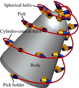
Fig. 4Numerical model
The reputable commercial software ABAQUS 6.12 (SIMULIA, Providence, RI, USA) based on the finite element method was chosen for its ability to model the dynamic contact problems in rock fragmentation by a cutting head. ABAQUS 6.12 was installed on an HP Z820 workstation, representing current technology (two six-core processors; 32 GB memory). Because the fully integrated first order solid elements exhibited shear locking, reduced integration with the second order solid elements was recommended to prevent the elements suffering from hourglassing and shear locking [27]. Twenty-node hexahedral reduced integrated elements (C3D20R) and ten-node modified quadratic tetrahedron elements (C3D10M) were used for rock and cutting head respectively. The total number of rock and pick elements was 4800000 and 60437, respectively, as shown in the mesh model (Fig. 4). The macroscopic mechanical characteristics of rock were described approximately by the brittle cracking model. Dynamic node-surface contact was used to deal with the contact problem between rock and picks, and that contact was redefined to realize the dynamic contact in rock fragmentation at the end of each time step in the numerical model.
Table 1Parameters of rock fragmentation model by cutting head
Parameter (unit) | Value |
Feeding speed (m/min) | 0.6, 0.9, 1.2, 1.5 |
Semi-conical angle of carbide tip () | 40 |
Diameter of carbide tip (mm) | 12 |
Cutting angle of pick () | 50 |
Rock length , height , and width (mm) | 700, 1000, 1000 |
Rotation speed (r/min) | 40, 50, 60, 70 |
Relative friction coefficient | 0.3 |
3. Experiment of rock fragmentation and verification of numerical model
3.1. Experimental rock fragmentation by cutting head
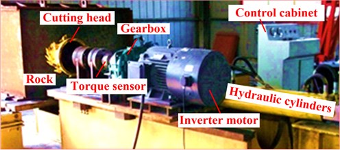
The experiment of rock fragmentation by cutting head as shown in Fig. 5 was carried out at the China University of Mining and Technology (Xuzhou) in the rock fragmentation test bed, and consisted mainly of inverter motor, feeding hydro-cylinder, gear-box, torque sensor, cutting head, control cabinet, and so on. A 30 kW inverter motor was used to simulate rock fragmentation experiments under different rotation speed conditions, and provided cutting torque to break rock. A feeding hydro-cylinder provided the axial force for rock fragmentation by the cutting head, and was able to realize the rock fragmentation experiments at different feeding speeds. A gearbox with a transmission ratio 10 was adopted to reduce the rotation speed of the motor, which could enlarge the power to break rock. A torque sensor with the range of 0-3000 N·m was selected to measure the torque of the cutting head in rock fragmentation. The control cabinet was designed to control and regulate the working parameters of the inverter motor, the feeding hydro-cylinder, and so on.
Fig. 5Test bed for rock fragmentation by roadheader
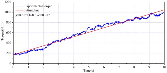
As a result of the limited ability of the rock fragmentation test bed and the difficulty of acquiring large natural rock, artificial rock was used as an appropriate substitute. Cement, sand, pulverized coal, and water were mixed for preparation of the artificial rock, and its mechanical characteristics were measured by a SANS universal material testing machine (MTS, China). The uniaxial comprehensive strength of the artificial rock (cement: sand: pulverized coal 1:2:7) was 3.8 MPa, and its corresponding tensile strength, elasticity modulus, and density were 0.3 MPa, 1.1 GPa and 1987 kg/m3, respectively. With feeding speed of 1200 mm/min and a rotation speed of 60 r/min, torque variation of the cutting head during rock fragmentation was obtained (Fig. 6). The value of the cutting torque increased with depth of penetration, and its fluctuation range increased with the number of picks participating in rock fragmentation. In addition, an impact and unloading effect appeared when the cutting head first contacted the rock, and the torque value equaled to 200 N·m at that moment. To better estimate the torque characteristics in rock fragmentation, the cutting time and torque were seen as an independent and dependent variables, respectively, and the torque variation was regressed using the least square method. According to the regression line (87.8168.8) in Fig. 6, the torque increased linearly with the cutting time, and the regression coefficient of 0.987 showed that the fitting line described the torque variation characteristics reliably and correctly. Furthermore, the slope of the regression line could be regarded as a characteristic index of torque variation in rock fragmentation.
Fig. 6Experimental torque
3.2. Verification of numerical model
The process of rock fragmentation by the cutting head of roadheader was simulated based on the numerical model developed, and the rock properties as well as the cutting parameters of the cutting head were consistent with those of the experiment. The torque of rock fragmentation obtained by the numerical model developed is shown in Fig. 7. The simulated torque increased with rock penetration depthand, its variation was consistent with the experimental torque. In particular, the torque fluctuation range increased with the rock penetration depth by the numerical method, and the torque value sometimes suddenly dropped close to zero during rock fragmentation. The reason was that the elements possessed failure and deletion features to simulate the rock fragmentation process. When the displacement or strain of element integral points reached failure displacement or strain, the element was deleted from the rock, and it did not obstruct the feeding movement of cutting head. Therefore, the force acting on some picks of the cutting head was close to zero for a short period of time until the cutting head re-contacted rock. After deletion of elements, some contacts failed between picks and rock, which caused the cutting torque to drop suddenly. Therefore, peak values were chosen to model the numerical cutting torque for comparison with the experimental torque. A rectangle with width of 3 % of cutting time was adopted to find the peak points, and the minimum value was 5 % of maximum cutting torque using the original software [28, 29]. Then, the peak values of the torque obtained by the numerical method were selected as shown in Fig. 7. The variation curve consisting of those points is shown in Fig. 8, which could be regarded as the torque in the rock fragmentation process [17, 30]. The regenerated torque variation corresponded well with the experimental torque, and the two torque value only had a small difference in the same penetration depth. In addition, the regenerated torque values had only small differences at the same penetration depth. Moreover, the regenerated torque was linearly regressed by the least square method, and the regression coefficient of 0.945 showed that the fitting line (82.5 34.5) describing the variation of peak values of cutting torque was feasible. When the regression slopes of torque obtained by the numerical and experimental methods were compared, the difference was only 6 % indicated that the torque variation characteristics determined by these two methods were similar, and also verified the correctness of the numerical model developed in this research. Fig. 9(a) shows the experimental kerf shape of artificial rock, and Fig. 9(b) and Fig. 9(c) show the kerf shape in different views by the numerical method. The similar morphology of rock kerf shapes from the two different methods also indicated that the numerical model could effectively predict the rock fragmentation process by cutting head.
Fig. 7Numerical torque and peaks
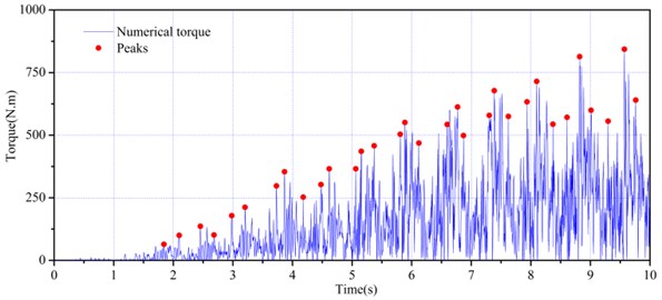
Fig. 8Fitting line of torque peaks
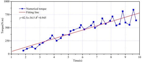
Fig. 9Rock morphology after rock fragmentation by roadheader
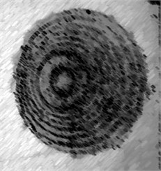
a) Experimental result
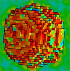
b) Numerical result
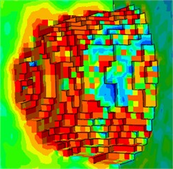
c) Cut view of numerical result
4. Discussion
The cutting head torque was affected by the combined action of rock on picks as well as by the factors influencing the pick cutting force. Therefore, investigation of the factors influencing the pick cutting force was the basis for the study of rock fragmentation by the cutting head. Researchers have set up some theoretical models for rock fragmentation by pick, and the model developed by Goktan [10], based on Evans’ theoretical models [8], described the relationship between theoretical and experimental pick cutting force well. By introducing motion parameters to express cutting depth, a new model was proposed in this study to illustrate the relationships between pick cutting force and cutting parameters, as follows:
where was the pick cutting force; was the feeding speed of cutting head; was the rotation speed of cutting head; was the number of spiral lines; was the rock tensile strength; was the semi-conical angle of the carbide tip; was the friction angle between rock and cutting head.
The relationships between pick cutting force and cutting parameters are shown in Fig. 10. The pick cutting force increased with the feeding speed of cutting head, rock tensile strength, and semi-conical angle of carbide tip, but decreased as the rotation speed of cutting head. The semi-conical angle of the carbide tip has generally been close to 45°, but considerable differences in rock properties have been reported with different tensile strengths. Therefore, in this study, rock fragmentation by cutting head with different feeding speeds, rotation speeds, and SLVSAs were investigated. In particular, pick slanting angle was an important parameter for the design of cutting head.
Fig. 10Relationship between pick cutting force and cutting parameters
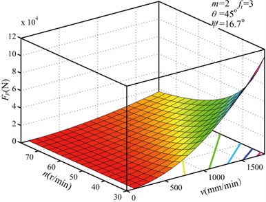
a) Variation of with and
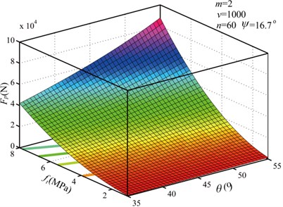
b) Variation of with and
4.1. Feeding speed of cutting head
For the drilling condition of the cutting head, the volume of rock fragmentation increased with feeding speed in unit time for a given rotation speed, and the cutting depth of the pick increased correspondingly. To simulate rock fragmentation by the cutting head, the object broken was natural limestone rock [31], whose mechanical properties are shown in Table 2. It was regarded as a broken object in the following simulations. With the rotation speed of 60 r/min, rock fragmentation by the cutting head was simulated with feeding speeds of 600 mm/min, 900 mm/min, 1200 mm/min and 1500 mm/min. Fig. 11 shown the variation curves of peak torque points and the corresponding regression line with different feeding speeds. It can be seen that the torque increased with feeding speed. The volume of rock fragmentation increased with feeding speed in unit time, such that the torque increased more quickly with higher feeding speeds. Meanwhile, the range of fluctuation increased with high feeding speed. To better estimate the influence of feeding speed on cutting torque, the corresponding peak torque points were regressed by the least square method. The slopes of fitting lines were 651, 761, 845, and 961, respectively. The relationship between the characteristic index of cutting torque and the feeding speed is shown in Fig. 12. The characteristic index increased with feeding speed according to quadraticfunction in a certain range, indicating that the rate of variation of cutting torque increased with feeding speed by a the quadratic law ( 0.00010.51 384.6).
Fig. 11Torque under different feeding speed
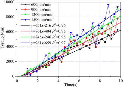
Fig. 12Relationship between CI and feeding speed
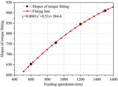
Table 2Mechanical properties of a natural limestone
Property | Value |
Uniaxial compressive strength (MPa) | 31.9 |
Brazilian tensile strength (MPa) | 3.9 |
Elastic modulus (GPa) | 7.6 |
Poisson’s ratio | 0.3 |
Density (kg/m3) | 2410 |
4.2. Rotation speed of cutting head
For the drilling condition of the cutting head, the volume of rock fragmentation decreased with rotation speed in unit time for a given feeding speed, and the cutting depth of pick decreased correspondingly. With a feeding speed of 1200 mm/min, the rock fragmentation was simulated with rotation speeds of 40 r/min, 50 r/min, 60 r/min and 70 r/min. The peak torque points and their fitting lines are shown in Fig. 13.
Fig. 13Torque under different rotation speed
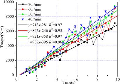
Fig. 14Relationship between CI and rotation speed
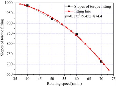
The torque decreased with the rotation speed in in unit time, such that the torque increased more quickly with lower rotation speed. In theory, the torque fluctuation range increased with the rock fragmentation volume of the cutting head in unit time, but there were no obvious differences with different rotating speeds, indicating that not only was the torque fluctuation range influenced by the cutting depth, but also the impact was influenced by rotation speed. The least square method was also adopted to fit the peak torque points at different rotation speeds, and the slopes of the regression lines were 987, 921, 845, and 713, respectively. The relationship between torque characteristic index and rotation speed is shown in Fig. 14, where the characteristic index decreased with the rotation speed according to a quadratic function ( –0.179.45 874.4).
4.3. Pick slanting angle
Pick slanting angle was an important parameter for cutting head design, and has a significant affect on the cutting head’s drilling performance. The pick slanting angle is defined by the included angle ( 90°) between a plane including the pick center line, a tangent line of pick motion trajectory, and a plane perpendicular to the axis of the cutting head. A new coordinate system was set up as shown in Fig. 15, which was parallel to the reference coordinate system of the cutting head shown in Fig. 4, and its origin and pick root were in the same position. belonged to the pick center line, and was the tangent line along the pick motion trajectory. was a plane including lines and , and was a plane perpendicular to the cutting head axis. Therefore, the pick slanting angle was equal to as shown in Fig. 15.
Fig. 15Geometrical relations of slanting angle
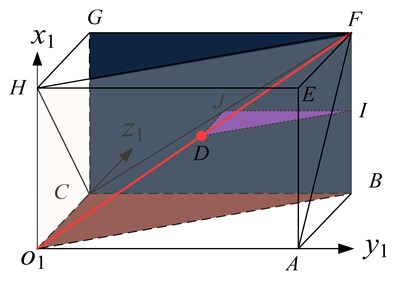
Fig. 16Variation of slanting angle
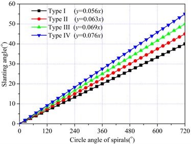
Fig. 17Torque under different type of slanting angle
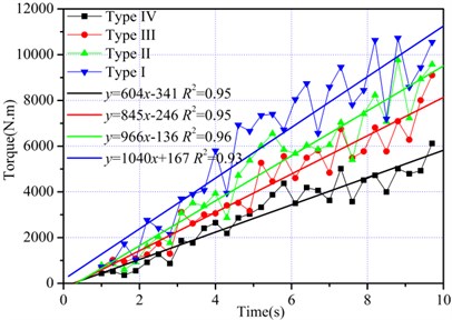
Fig. 18Relationship between CI and SLVSA
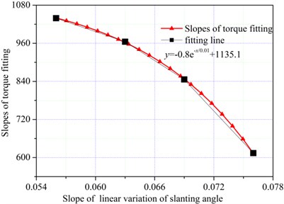
To ensure the drilling performance of the cutting head, the pick slanting angle was different in various positions, it generally increased along with the spiral angle. With the feeding speed of 1200 mm/min and a rotation speed of 60 r/min, rock fragmentation by the cutting head was simulated for four different combinations of pick slanting angles. And variation curves of the slanting angle of different combinations are shown in Fig. 16. Meanwhile, Fig. 17 shows the variation curves of peak torque points and their regression lines for four different combinations of pick slanting angle, indicating that the torque decreased with decrease of the pick slanting angle. Moreover, the drilling performance was enhanced with a large slanting angle, the reason being that the rock breaking performance improved in the axis direction of cutting head. With a small slanting angle, the pick holder easily compressed the rock, generating a high pick cutting force. The least square method was adopted to fit the peak torque points with four different combinations of pick slanting angle, and the slopes of the regression lines were 1039, 965, 846, and 604, respectively. The relationship between the torque characteristic index and SLVSA is shown in Fig. 18, where the characteristic index decreased with SLVSA according to the exponential function ( 0.8 1135.1).
5. Conclusions
Using a brittle cracking model for rock, the finite element method was adopted to develop a numerical model of rock fragmentation by cutting head. Experimental and numerical torque variations were evaluated. Then, a series of rock fragmentations were simulated with different cutting parameters. From the experimental and numerical results, some conclusions can be obtained as follows:
1) A rock fragmentation test bed was developed for the rock cutting experiments by the cutting head of a roadheader. An artificial rock, consisting of cement, river sand, pulverized coal and water, was fragmented by a scaled cutting head. The cutting torque increased with an increase in penetration depth, and its fluctuation range increased with an increase in number of picks participating in rock fragmentation.
2) The torque variation regenerated from the numerical result was consistent with the experimental torque, and the two torque values showed little difference in penetration depth. The difference between the slope of the fitting line of the regenerated torque and that of experimental torque was 6 %, and the morphologies of the rock kerf shape from experiment and numerical simulation were similar.
3) Based on our investigation of factors influencing pick cutting force, the rock fragmentation by a cutting head with cutting parameters was investigated. The torque characteristic index was a quadratic function, that increased with an increase of feeding speed but decreased with an increase of rotation speed. With the increase of the slope of linear variation of slanting angel, the torque characteristic index decreased according to an exponential function.
References
-
Acaroglu O., Ergin H. A new method to evaluation roadheader operational stability. Tunneling and Underground Space Technology, Vol. 21, Issue 2, 2006, p. 172-179.
-
Bilgin N., Dincer T., Copur H., Erdogan M. Some geological and geotechnical factors affecting the performance of a roadheader in an inclined tunnel. Tunneling and Underground Space Technology, Vol. 19, Issue 6, 2004, p. 629-636.
-
Altindag R. Correlation of specific energy with rock brittleness concepts on rock cutting. Journal of the South African Institute of Mining and Metallurgy, Vol. 103, Issue 3, 2003, p. 163-171.
-
Balci C., Bilgin N. Correlative study of linear small and full-scale rock cutting tests to select mechanized excavation machines. International Journal of Rock Mechanics and Mining Sciences. Vol. 44, Issue 3, 2007, p. 468-476.
-
Tiryaki B., Cagatay Dikmen A. Effects of rock properties on specific cutting energy in linear cutting of sandstones by picks. Rock Mechanics and Rock Engineering, Vol. 39, Issue 2, 2006, p. 89-120.
-
Kim E., Rostami J., Swope C. Full scale linear cutting experiment to examine conical bit rotation. Journal of Mining Science, Vol. 48, Issue 5, 2012, p. 882-895.
-
Tiryaki B., Boland J. N., Li X. S. Empirical models to predict mean cutting forces on pointattack pick cutters. International Journal of Rock Mechanics and Mining Sciences, Vol. 47, Issue 5, 2010, p. 858-864.
-
Evans I. A theory of the picks cutting force for point-attack. International Journal of Mining Engineering, Vol. 2, Issue 1, 1984, p. 63-71.
-
Jonak J., Jerzy P. Mathematical model and results of rock cutting modeling. Journal of Mining Science, Vol. 37, Issue 6, 2001, p. 615-618.
-
Goktan R. M., Gunes N. A semi-empirical approach to cuttingforce prediction for point-attack picks. The Journal of the South African Institute of Mining and Metallurgy, Vol. 105, 2005, p. 257-263.
-
Bao R. H., Zhang L. C., Yao Q. Y., Lunn Y. Estimating the peak indentation force of the edge chipping of rocks using single point-attack pick. Rock Mechanics and Rock Engineering, Vol. 44, 2011, p. 339-347.
-
Gao K. D., Du C. L., Jiang H. X., Liu S. Y. A theoretical model for predicting the peak cutting force of conical picks. Frattura e Integrita Strutturale, Vol. 27, 2014, p. 43-52.
-
Su O., Akcin N. A. Numerical simulation of rock cutting using the discrete element method. International Journal of Rock Mechanics and Mining Sciences, Vol. 48, Issue 3, 2011, p. 434-442.
-
John P., Loui U. M., Rao K. Numerical studies on chip formation in drag-pick cutting of rocks. Geotechnical and Geological Engineering, Vol. 30, Issue 1, 2011, p. 145-161.
-
Rojek J., Onate E., Labra C., Kargl H. Discrete element simulation of rock cutting. International Journal of Rock Mechanics and Mining Sciences. Vol. 48, Issue 6, 2011, p. 996-1100.
-
Jiang H. X., Du C. L., Liu S. Y., Gao K. D. Numerical simulation of rock fragmentation process by roadheaderpick. Journal of Vibroengineering, Vol. 15, Issue 4, 2013, p. 1087-1817.
-
Van Wyk G., Els D. N. J., Akdogan G., et al. Discrete element simulation of tribological interactions in rock cutting. International Journal of Rock Mechanics and Mining Sciences, Vol. 65, 2014, p. 8-19.
-
Menezes P. L., Lovell M. R., Avdeev I. V., et al. Studies on the formation of discontinuous chips during rock cutting using an explicit finite element model. The International Journal of Advanced Manufacturing Technology, Vol. 70, 2014, p. 635-648.
-
Liu S. Y., Du C. L., Cui X. X., Cheng X. Model test of the cutting properties of a shearer drum. Mining Science and Technology, Vol. 19, 2009, p. 74-78.
-
Yu B. Numerical Simulation of Continuous Miner Rock Cutting Process. Ph.D. Dissertation, West Virginia University, West Virginia, 2005.
-
Yu B., Khair A. W. Numerical modeling of rock ridge breakage in rotary cutting. Proceedings of the 1st Canada-US Rock Mechanics Symposium – Rock Mechanics Meeting Society’s Challenges and Demands, Vancouver, BC, Canada, 2007, p. 519-526.
-
Li X. Y., Huang B. B., Ma G. Y., Zeng Q. L. Study on roadheader cutting load at different properties of coal and rock. Scientific World Journal, 2013, p. 624512.
-
Simulia Company A Cracking Model for Concrete and Other Brittle Materials of the Abaqus Theory Manual. Rhode Island, Simulia, 2013.
-
Ou H. G., Li R. F., Gong J. X. An improved mixed approach of finite element method for three-dimensional elastic contact problems with friction. Proceedings of 22nd Midwestern Mechanics Conference, Rolla, Missouri, 1991.
-
Ou H. G., Li R. F., Gong J. X. A mixed finite element algorithm of three-dimensional impact-dynamic contact problems. Journal of Chongqing University, Vol. 17, Issue 2, 1994, p. 52-57, (in Chinese).
-
Mustafa Eyyuboglu E., Bolukbasi N. Effects of circumferential pick spacing on boom type roadheader cutting head performance. Tunnelling and Underground Space Technology, Vol. 20, Issue 5, 2005, p. 418-425.
-
Tsouknidas A., Savvakis S., Asaniotis Y., et al. The effect of kyphoplasty parameters on the dynamic load transfer within the lumbar spine considering the response of a bio-realistic spine segment. Clinical Biomechanics, Vol. 28, Issues 9-10, 2013, p. 949-955.
-
Lu X., Li H. Wavelet analysis of pressure fluctuation signals in a bubbling fluidized bed. Chemical Engineering Journal, Vol. 75, Issue 2, 1999, p. 113-119.
-
Dong Z. H., Shi W., Guo X. P. Initiation and repassivation of pitting corrosion of carbon steel in carbonated concrete pore solution. Corrosion Science, Vol. 53, Issue 4, 2011, p. 1322-1330.
-
Cho J. W., Jeon S., Yu S. H., Chang S. H. Optimum spacing of TBM disc cutters: A numerical simulation using the three-dimensional dynamic fracturing method. Tunneling and Underground Space Technology, Vol. 25, Issue 3, 2010, p. 230-244.
-
Balci C., Tumac D. Investigation into the effects of different rocks on rock cuttability by a V-typedisc cutter. Tunneling and Underground Space Technology, Vol. 30, Issue 6, 2012, p. 183-193.
About this article
The authors would like to acknowledge the Foundation National Natural Science Foundation of China (51375478) and the Priority Academic Program Development of Jiangsu High Education Institute of China.
