Abstract
Buckling stability of the thin – layered rubber-metal package of flat circular shape is considered in this work. TRME packages using as vibration isolator (including seismic protection) usually work under heavy compressive loads, which may lead to buckling failure. Next formulas for package design are derived: the dependence of the critical force on layers geometry, on mechanical properties of layers materials, on packages end-fixity conditions. The dependence of mechanical modules of elastomeric on the compressive load level is taken into account. The solutions obtained are compared with experimental data of other authors.
1. Introduction
Rubber (natural and synthetic) as construction material has a number of valuable properties: high elasticity, resistance to environmental influences, good dynamic characteristics [1, 2]. Laminated elastomer (or reinforced elastomer) is the anisotropic elastic element of alternating thin layers of rubber (or other elastomer) and metal (or hard plastic) assembled by gluing or vulcanizing in a package of three or more layers having the large load carrying capacity (more than 30 MPa) in normal to the layer direction and higher compliance (50 ... 200 % of relative deformation) in the transversal direction. This allows to obtain the structures, which axial compression stiffness is in several orders greater than shear stiffness. Packages of thin-layered rubber-metal elements (hereinafter referred to as TRME) are successfully used as vibration isolator, shock absorbers, compensating devices, bearing, joints etc. [1, 3] In practice TRME packages of different geometrical form are used: flat of various shape, cylindrical, conical etc. Elastomeric layer is considered as thin if its width/thickness ratio is much more than 10. Multilayered packets of TRME have extensive use almost in all spheres of engineering and construction (joints and bearings for various applications, support of engineering structures, vibration and shock absorbers etc.). In flat-type packages working under significant compressive loads, the buckling of the middle layers of packet is observed, i.e. package loses buckling stability, which leads to decreasing of performance capabilities of packages and their failure. Buckling has shear instability form (the layers are shifted sidewise), rather than bending (as in the classical theory of rods stability). This occurs because of TRME stiffness under axial compression and bending stiffness are in several orders greater than the shear stiffness.
Gent A. N. considers the stability of structures with thick rubber layers (with the shape factor ≈ 1) based on the classical Timoshenko theory of rods [3]. This approach and the main position of Gent’s work was later used by many authors [5-8], but further investigations shows that application of these solution to thin ruber-metal elements lead to significant errors [2, 4]. Many successive works deal with TRME package buckling stability [8-11], the method of bending stiffness calculation on the assumption that middle surface of elastomeric layer remains flat under deformation was elaborated.
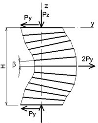
When designing TRME packages to improve their operational characteristics and increase permissible rate of compressive loads, it is necessary to have an analytical expression (preferably in a simple manner) to calculate the critical external load taking into account TRME geometric parameters, scheme of external load imposing and method of TRME packet fastening, as well as mechanical properties of materials. In this study all mentioned above factors are taken into account on the example of critical force calculation for the flat-type TRME of circular shape (Fig. 1).
2. Mathematical models of TRME and analytical solutions
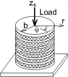
In mentioned above studies it is assumed that: nonelastomeric layers are nondeformable, external forces are conservative, elastomeric and nonelastomeric layers are rigidly connected to each other, the deformation of each individual TRME are linear. Besides that, the assumptions are introduced that the elastomeric material layer is volumetrical incompressible and its mechanical properties are not dependent on the rate of external loading. But there are not argumentation of the above listed assumptions applicability domain and estimation of their influence on numerical value of the critical forces. In given paper the methodology of calculating the critical force for TRME package buckling taking into account the weak compressibility of elastomeric layers and shear modulus dependence on the load level which were not considered in the works [2] is discussed. As an example the stability problem of the circular-type flat TRME package under axial compression between two flat parallel plates by the force is considered. In Fig. 2 the forms of loss of stability of TRME device under axial compression are shown; because the compression and tension stiffness are much greater than share stiffness, the considering buckled shape includes share deformation (Fig. 2(c)). TRME package (of thickness ) consists of individual identical sections. Each section (thickness ) consists of nondeformable metal plate (thickness – ) and is vulcanised to an elastomeric layer (thickness – and sectional area – ), which deformation is considered as small. When calculating the shear stiffness of elastomeric element of shear force scheme of simple share is applied; for bending stiffness calculating – scheme when the metal plates are rotated with respect to each other relative to the axis of symmetry.
Fig. 1Multilayer elastomeric structures examples: a) flat rectangular, b) flat circular
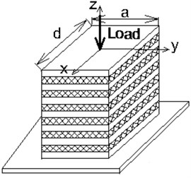
a)
b)
Fig. 2Loss of stability of TRME device under axial compression: a) Euler buckling, b) pure shear buckling, c) Euler buckling with shear contribution
a)
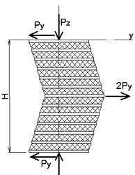
b)
c)
2.1. Models of TRME package
Based on Timoshenko beam model the critical force was derived in [2] for scheem a) and c).
In this paper the loss of stability of TRME package with fixed end point is discussed; in particular, Euler buckling with shear contribution. The critical force for this case:
Shear stiffness of the elastomeric layer , determined from pure shear scheme, and bending stiffness without accounting of elastomeric layer low compressibility is:
where: – shear modulus of the elastomer; – axial moment of inertia of the cross section of element of the TRME package; – shape factor; – empirical coefficient; – loaded surface area of the block; – free surface area.
This dependence (1) give acceptable results for elastomeric layers with a shape factor 1-2 (or 5), small deformations and for specific axial load till 5-10 MPa [3]. To determine the critical axial compression force for small deformations domain, thin layers ( 10) and high specific axial loads (10 MPa) formulas may be used if instead of stiffness (2) to substitute shear and bending stiffness calculating with accounting of elastomeric layer weak compressibility and the loading level effect on shear modulus of the elastomeric material.
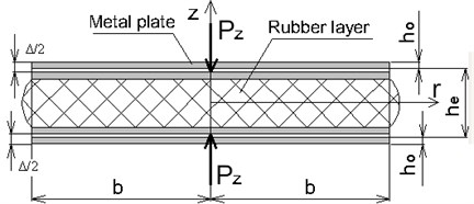
Fig. 3Scheme of compression of TRME section
2.2. Mathematical models of simple TRME layer
Flat circular TRME is considered in cylindrical coordinates system , , (Fig. 1).
Shear stiffness of the precompressed thin elastomeric layer determined from pure shear scheme (Fig. 4) is calculated by the formula:
where , – axial deformation of the elastomeric layer (Fig. 3).
This dependence is confirmed by shear deformation experiments on the preloaded TRME [8, 10]. Flat circular TRME is considered in cylindrical coordinates. Required dependencies “–” and “–” (“axial force – displacement” and “bending moment – rotation angle”) are defined by means of the Ritz’s method, minimizing the additional strain energy [8], subject to the weak compressibility of elastomer, assuming that metal layers are nondeformable either (or may undergo only a plane tensile strain):
where:
here: – bulk modulus of elastomeric layer, – Poisson ratio, – average stress (called spesific hydrostatic pressure ). Stress state of the elastomeric layer is determined by the superposition of shear stress on the hydrostatic pressure [8-10]. Stress components must satisfy the equilibrium equations and boundary conditions on the shear surface of the elastomeric layer.
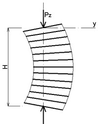
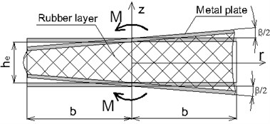
In the case of bending (load scheme is given in Fig. 5) for the stress distribution in the middle layer of flat TRME, the hypothesis is applied:
With regard of this, the equation of equilibrium in the volume of the elastomeric layer will be satisfied if:
Fig. 4Scheme of shear for TRME section
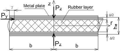
Fig. 5Scheme of bending for TRME section
Boundary conditions for stress on the free surface of the elastomeric layer are:
Taking into account the boundary conditions equations for stress functions are chosen:
Constants , , are found by minimizing of the functional (4) of additional energy:
from system of functional minimum .
The dependence “–” and, hence, bending stiffness is defined from the equation:
Bending stiffness of elastomeric layer:
Bending stiffness without accounting of elastomeric layer low compressibility ():
Dependences (6) and (7) may be used in the case of the precompressed TRME at low axial deformation under preloading. In case of average deformation the dependence may be obtained from (6) using the delta method of integration [8, 10]:
Bending stiffness without accounting of elastomeric layer low compressibility:
In the case of axial compression (load scheme is given in Fig. 3) “–” dependence is defined by the same way, i.e. choosing the relevant functions for , , , , , and using the principle of minimum complementary energy. dependence accounting low compressibility of elastomer:
“–” dependence without taken into account of elastomeric layer low compressibility:
Dependences (10), (11) are used in the case of low axial deformation. In case of average deformation “–” dependence taken into account of elastomeric layer low compressibility, is obtained using the delta – method of integration [8, 10]:
“–” dependences without accounting of elastomeric layer low compressibility:
2.3. Material model of elastomer
Results of experiments on thin TRME compression [2; 11] show that at relatively small strains (up to 10 %-15 %), specific loading () may reach 200 MPa. The dependence of the “force-displacement” has highly nonlinear character, indicating that the mechanical modules of elastomer depend on the level of specific compressive strength even in small deformations area. In experimental studies it is shown that shear and bulk modulus of elastomeric layer and depend on intensity of the specific loading if is more than 5 MPa [11].
In order to take into account load intensity influence on “force – displacement” dependence and on the critical force it is proposed to substitute the values and instead of modules and . For thin flat elastomeric layers it can be assumed with sufficient accuracy that (where – the area of plane layer). This approach allows calculating of and from the volumetric “tension – compression” experiments with accuracy up to the assumption of small deformations. Due to lack of experimental data it is proposed in [11] at first approximation to assume that the dependence of and has the same type:
where factor is defined from experiment on pure volumetric compression.
This equation allows to estimate critical force for large values of specific external compressive load. The order of critical buckling force calculation: in accordance with (1), (2) the preliminary force is defined; for this hydrostatic pressure and displacement in accordance with (10), (12), (14) are defined; depending on value bending and shear stiffness (, ) are defined using (6), (8), (3), (14); received and are substituted in (1) and is calculated. If necessary, calculation is repeated till the coinsidence of received and previous critical forces.
3. Numerical examples
The results of critical forces calculation for flat rectangular TRME package with typical in industrial application dimensions are presented bellow. Plots of buckling force dependence on the number of section in packet are given for TRME, which was fabricated and tested in Moscow Institute “Teploprojekt”. For thin layered packages experimental critical force is much greater than calculated in accordance with conventional Eqs. (1) and (2).
In Fig. 6 the critical buckling force plots for sample with brass bonded layers is given; layer dimensions: 27.5 mm, 1.0 mm, 0.1 mm, section height 1.10 mm, 27.5, TRME package height , – number of sections. Mechanical properties of elastomer: 1.17 MPa, 2760 MPa, 0.4997, 0.001.
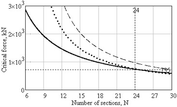
In Fig. 7 critical buckling force plots is presented for the sample of the same material with the same and , but 0.5 mm, 0.6 mm, shape factor 55.
Specific load in all case is more than 100 MPa. It is seen from the plots how critical force value depends on thickness of elastomeric layers and on the number of sections.
Fig. 6Plots of critical force dependence on number of sections with he= 1 mm:___ – in accordance with Eq. (1) and (2), ..... – in accordance with (8), (12), (3), (1), _ _ _ – in accordance with (8), (12), (3), (1), taking into account (13)
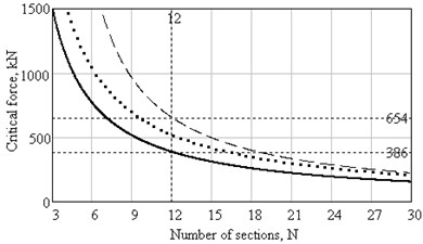
Fig. 7Plots of critical force dependence on number of sections with he= 0.5 mm: ___ – in accordance with Eq. (1) and (2), ….. – in accordance with (7), (11), (3), (1), _ _ _ – in accordance with (6), (10), (3), (1) and (13)
4. Conclusions
This work presented the methodology of the buckling force calculation for thin-layered rubber-metal packages widely used as vibroisolators, shock absorbers, compensation devices. Such devices usually carry very large load and should be check on buckling. Three approaches are discussed: conventional, taking into account the thickness of elastomeric layers, taking into account the thickness of elastomeric layers and changing of the elastomeric mechanical properties (shear and bulk modules) depending on pressure. The results of numerical examples show that at number of layers in package increasing the critical force value became closer. Each type of TRME demands the individual approach.
References
-
Kelly J. M., Konstantinidas D. A. Mechanics of Rubber Bearings for Seismic and Vibration Isolation. John Wiley & Sons, UK, 2011.
-
Gusjatinskaja N. S. Application of Thin Layer Rubber-Metal Elements (TRME) in Machine-Tools and Other Engines. Mashinostroenie, Moscow, 1978, (in Russian).
-
Gent A. N. Elastic stability of rubber compression springs. Journal Mechanical Engineering Sciences, Vol. 6, Issue 4, 1964, p. 318-326.
-
Gent A. N., Meinecke E. A. Compression, bending and shear of bonded rubber blocks. Journal of Polymer Engineering, Vol. 10, Issue 1, 1970, p. 48-53.
-
Leikand M. A. Critical values of compressive loads for multilayer rubber-metal elements. Proceeding of Conference Products of Highly Elastic Materials Design Methods, Riga, 1983, p. 22-24, (in Russian).
-
Malkov V. M. Mechanics of Multilayered Elastomeric Structures. St. Petersburg University Press, St.-Petersburg, 1998, (in Russian).
-
Leikand M. A., Lavendel E. E., Khrichikova V. A. Calculation of compression rigidity of thin-layer rubber-metal elements. In book: Problems of Dynamics and Strength, Issue 38, Zinatne, Riga, 1981, p. 57-63, (in Russian).
-
Lavendel E. E. Applied Methods for Calculating the Product of a Highly Elastic Materials. Zinatne, Riga, 1980, (in Russian).
-
Lavendel E. E. Design of Fabricated Rubber Products. Mashinostroenie, Moscow, 1976, (in Russian).
-
Dimnikov S.I. Calculation of Rubber Elements of Constructions. Zinatne, Riga, 1991, (in Russian).
-
Leikand M. A., Lavendel E. E., Lvov S. V. Experimental research of volume change of rubber under compression and tension. In book: Problems of Dynamics and Strength, Riga, Issue 38, 1982, p. 49-54, (in Russian).
About this article
