Abstract
The paper presents the results of research related to the possibility of using an intelligent workpiece holder with adjustable stiffness, during end milling process. Machining a one side supported flexible workpiece will be performed with constant spindle speed and feed speed. In order to avoid hazardous vibration, stiffness of the especially designed spring (mounted in a workpiece holder) will be modified off-line. In order to predict the accuracy of the proposed method, appropriate simulations were performed. As a simplified model of the flat workpiece it was applied the Euler-Bernoulli bar with possibility of identifying the two lowest normal modes. On this basis and for approaching optimal spindle speeds, the mean of adjusting relevant stiffness of the holder is invented.
1. Introduction
Milling flexible details is difficult problem because such objects can be prone to vibration especially when the workpiece is difficult to fix or cannot be fixed during machining. In such a case, tool-workpiece relative vibration plays a principal role, because in certain conditions, it may lead to a loss of stability and cause generation of very hazardous self-excited chatter vibration [1].
One group of the many methods of preventing dangerous vibration during machining depends on building special workpiece holders that either in a passive [2] or an active [3-5] way cancel this unwanted phenomenon. Now this is a different approach compared from the commonly used special tool holders [6]. In process of the designing are often used also some instruments of the mechatronic approach, i.e. the FE modelling, experimental modal analysis (EMA) [6, 7] and Hardware-In-the-Loop-Simulation (HILS) [8]. In the presented case, workpiece holder is considered as one-degree-of-freedom structure with off-line adjustable stiffness.
2. Simulations
In order to describe dynamic of milling process, proportional model is applied [9]. In this model cutting force components depend proportionally on cutting layer thickness, and also – on changing with time depth of cutting. Resultant cutting force lies in the orthogonal plane. With dependence of the direction of action, three force components can be separated, i.e. principal force acting along nominal cutting velocity Eq. (1), thrust force acting along change in cutting layer thickness Eq. (2) and the force acting in parallel to the tool axis, being equal to 0 Eq. (3). Thus appropriate equations are as follows:
where: – average dynamic specific cutting pressure, – depth of cutting, – desired cutting layer thickness, – dynamic change in cutting layer thickness, – cutting force ratio, – time-delay.
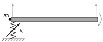
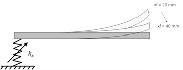
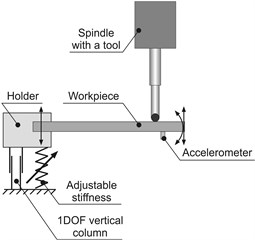
In order to perform simulations, a simplified model of the flat workpiece (based on the Euler-Bernoulli bar finite element) is applied. Appropriate matrices of mass, stiffness and damping were defined [10]. The considered degrees of freedom (DOF) of the model are shown in Fig. 1(a). First step was to adjust the setting of screw position being relative to stiffness of the holder’s spring. The selected values are shown in Table 1. In these cases, boundary normal modes corresponding to first natural frequencies of the system are shown in Fig. 1(b).
Fig. 1Scheme of the simplified workpiece model, a) the considered DOF are denoted with grey arrows, b) calculated normal modes related to screw position xf
a)
b)
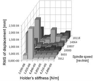
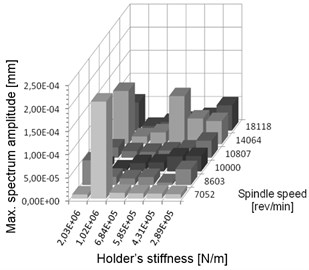
Fig. 2a) Summary of vibration displacements and b) maximum value of corresponding amplitude in spectrum for chosen simulated pairs of spindle speeds and stiffness settings
a)
b)
Table 1Selected screw position and corresponding stiffness of the spring
Screw position [mm] | Stiffness [N/m] |
20 | 2.3100×10⁶ |
25 | 1.1827×10⁶ |
30 | 6.8444×10⁵ |
35 | 4.3102×10⁵ |
40 | 2.8875×10⁵ |
In the next step, relevant optimal spindle speeds are calculated by using the generalised Liao-Young condition [9, 11] Eq. (4):
where: – natural frequency no. of the workpiece [Hz], – requested spindle speed [rev/min], – number of cutting edges of the milling tool.
Computation is performed for following data: workpiece material – aluminium alloy EN AW-6101A, density 2.7×10³ kg/m3, Young modulus 7×10¹⁰ N/m2, workpiece length 0.160 m, cross section area 2.5×10⁻⁴ m2, area moment of inertia 5.2083×10⁻¹⁰ m4, lumped mass of the holder’s moving parts 2 kg. Results of simulations confirmed that for chosen stiffness value the calculated spindle speed is really optimal and, on the other hand for desired spindle speed the stiffness is really appropriate. The summarized results for all calculated cases are presented in Fig. 2.
The shown above results of simulations confirm that for a spindle speed between 10000 and 14064 rev/min the adjusted stiffness values of the holder are correct. It may be noted that for non-optimal pairs stiffness-spindle speed displacement in vibration may be very high.
3. Variable stiffness holder
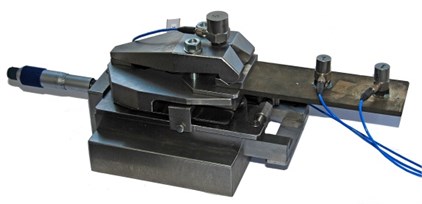
Satisfactory results of the simulation allowed, based on the conceptual model Fig. 3(a), to design and build a real workpiece holder with adjustable stiffness support, shown in Fig. 3(b). Such original holder can be easily mounted on the machine table. The required spring stiffness is set by the micrometer screw adjustment.
Fig. 3Variable stiffness holder: a) conceptual model, b) real original holder with mounted thin plate (workpiece) on which accelerometers are installed
a)
b)
Fig. 4Natural frequencies of first normal mode of the steel workpiece fixed in holder, as well as – holder with and without workpiece, with respect to setting of the micrometer screw, xf= 1 mm – minimum stiffness, xf= 25 mm – maximum stiffness
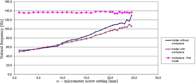
In order to investigate the influence of adjustable stiffness holder on first natural frequency of the workpiece, suitable modal tests were carried out for different settings of micrometer screw. By using the attached accelerometers Fig. 3(b) modal tests were performed for holder with and without fixed workpiece. Also natural frequencies of the workpiece (made of steel and bronze) were identified. The results are shown in Fig. 4.
In accordance with the expectation, due to increase of holder’s stiffness, natural frequency of the holder grows as well. In turn, change in the stiffness does not influence the first natural frequency of the own workpiece. It is about 136 Hz in case of steel, and 120 Hz in case of bronze (not shown in figure). However, a presence of flexible workpiece results that despite unchangeable own natural frequency of the workpiece, the latter will vibrate with dominant natural frequency of the couple “holder-workpiece”. And this natural frequency (not the own of the workpiece) is related with the optimal spindle speed. Note that when we adjust maximum stiffness of the holder (i.e. maximum screw setting), a curve of natural frequencies of couple “holder with workpiece” approaches curve of own natural frequencies of the workpiece. In such a case fixing the workpiece is almost perfectly rigid.
Also the carried out simulations showed that the maximum amplitudes in spectrum are significantly smaller, when the stiffness adjustment is optimal.
4. Conclusions
The presented results of calculations and simulations showed that changing dynamic properties of the workpiece is possible with the use of the proposed new mounting device. It was evidenced that only in case of a proper optimal combination of these two parameters i.e. holder stiffness and spindle speed we can obtain lowest values of root mean square (RMS) of displacement of vibration. The originally designed and built adjustable stiffness holder has a great potential for commercial use in real machining processes. In a standard usage of perfectly rigid holder, choosing the proper spindle speed on a basis of the Liao-Young condition was one of the method of vibration reduction. However the calculated optimal spindle speed might not be optimal from a point of view of e.g. technological properties of the machine tool. The proposed easily adjustable stiffness holder allows tuning dynamic properties of the workpiece in such a way that for a desired spindle speed the generalised Liao-Young condition is accomplished in a wide range of operational spindle speeds of the milling machine.
Future work will provide confirmation of the results during the real milling process.
References
-
Chodnicki M., Kaliński K. J., Galewski M. A. Vibration surveillance during milling flexible details with the use of active optimal control. Journal of Low Frequency Noise, Vibration and Active Control, Vol. 32, Issue 1-2, 2013, p. 145-156.
-
Rao M. K., Mohan V. S. Experimental analysis of passive damping technique on conventional radial drilling machine tool bed using composite materials. International Journal of Mining, Metallurgy and Mechanical Engineering, Vol. 1, Issue 2, 2013, p. 128-131.
-
Parus A., Hoffmenn M., Okulik T. Suppression of the work-piece vibrations in milling using active clamp system. Vibration Problems ICOVP, Vol. 139, 2011, p. 455-461.
-
Gao Y., Zhang D., Yu C. W. Dynamics of a high performance workpiece table for active control during precision grinding. Proceedings of the ASPE Spring Topical Meeting, Philadelphia, 2001, p. 29-32.
-
Rashid A., Nicolescu C. M. Active vibration control in palletized workholding system for milling. International Journal of Machine Toll and Manufacture, Vol. 46, 2006, p. 1626-1636.
-
Neugebauer R., Denkena B., Wegener K. Mechatronic systems for machine tools. Annals of the CIRP, Vol. 56, Issue 2, 2007, p. 657-686.
-
Deger Y. Optimisation of the dynamic behaviour of a machine tool mounting device. FANET/NAFEMS Seminar, FEM in Structural Dynamics, Wiesbaden, 2001.
-
Kaliński K. J., Galewski M. A. Vibration surveillance supported by hardware-in-the-loop simulation in milling of flexible workpieces. Mechatronics, 2014, p. 12.
-
Kaliński K. J. A Surveillance of Dynamic Processes in Mechanical Systems. Gdańsk University of Technology Publishers, Gdańsk, Poland, p. 2012, (in Polish).
-
Kaliński K. J., Chodnicki M., Mazur M. R., Galewski M. A. Vibration Surveillance System with Variable Stiffness Holder for Milling Flexible Details. Applied Non-Linear Dynamical Systems, Springer International Publishing Switzerland, 2014, p. 10.
-
Liao Y. S., Young Y. C. A new on-line spindle speed regulation strategy for chatter control. International Journal of Machine Tools and Manufacture, Vol. 36, Issue 5, 1996, p. 651-660.
About this article
