Abstract
In this work, the nonlinear dynamic characteristics of a large-scale tilting pad journal bearings-rotor system with oil-film force model are investigated. The oil-film force of the 4-tilting-pad journal bearings considering oil cavitation is studied, and it is indicated that preload coefficient, wrapping and swing angle of pad have effects on the force. The system state trajectory, Poincaré maps, frequency spectra and bifurcation diagram are constructed to analyse the nonlinear dynamic characteristics of the double cantilever rotor supported by the tilting pad journal bearings in a large-scale turbo expander. The result from the numerical analysis is in agreement with behaviors of the turbo expander, and it is shown that the tilting pad journal bearings are more stable because of better oil-film distribution and larger oil-film force than that of the conventional plain bearing. Oil whirl and oil whip have an important influence on vibration of the rotor system. The study makes sense to improvement of the turbo expander and may contribute to a further understanding of its nonlinear dynamics.
1. Introduction
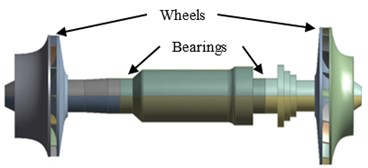
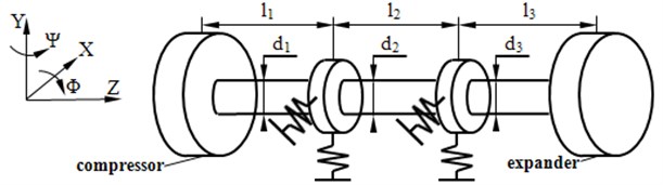
A double cantilever rotor is a typical structure, which is widely used in rotating machines, e.g. turbo expander. As shown in Fig. 1, the double cantilever rotor constitutes of a shaft and two wheels, which are overhang at both ends of the shaft. The rotor is supported by two tilting pad journal bearings at the location shown in Fig. 1. At present, the turbo expander has a tendency towards large-scale with the industry development.
Ying [1] studied the dynamic behaviors of a rotor system with foundation excitation in a turbo charger. Jing [2] took crack into account and revealed the nonlinear characteristics of a turbo charger. Tian [3] used a floating ring bearing in the rotor system of a turbo charger with engine excitation. Li [4] modeled a rotor system using Modelica and gave an example on a turbo expander with crack, rub-impact and pedestal looseness, and Li [5, 6] studied dispersion of lamb waves that could be used to locate the crack fault occurring in the rotor system. Rimpel [7] studied the dynamic characteristics of a high rotating speed turbo expander.
Fig. 1Structure of double cantilever rotor
The tilting pad journal bearings are widely used in modern rotating machines for its inherent stability and self-alignment ability, which can be categorized as a kind of plain bearings. The main difference between the tilting pad journal bearings and the conventional plain one is that the bushing of the tilting pad journal bearings is replaced with several pads supported by pivots instead of a whole circular ring. Furthermore, the pad swings around the pivot for a small angle, which is helpful to keep the rotor run stably.
The tilting pad journal bearings were first applied in industry in 1940s. In the earlier years, researchers such as Boyd [8] supposed that they performed under an absolutely stable condition theoretically and the journal supported by them vibrated less serious than on the conventional one. In 1960s, some researchers dedicated on linearizing model of the tilting pad journal bearings to obtain dynamic coefficients. Lund [9] gave curves of the dynamic coefficients of the bearings with 4-pad, 5-pad, 8-pad and 12-pad respectively, supposing the swing of pad is synchronous with the rotating speed of the rotor. Nicholas [10] applied FEM to study the coefficients of them with 5-pad. Orcutt [11] obtained relationship between the dynamic coefficients of the bearings and Reynolds number. After 1980s, the absolutely stable characteristics of the tilting pad journal bearings were questioned by researchers such as Parsell [12] and Barrett [13]. Recently some experts focus on the structure property of the tilting pad journal bearings. Lund and Pedersen [14] gave the dynamic coefficients considering elasticity of the pad. Earles indicated that the critical speed of the tilting pad journal bearings-rotor system would decrease if the stiffness of the pivot was taken into account [15, 16]. White and Chan [17] studied subsynchronous behaviors of the tilting pad journal bearings. Yang and Rodkiewicz [18] considered thermal effect and presented numerical analysis on the bearings. Dimond [19] deduced modal frequency response on the 4-tilting-pad journal bearings with spherical pivot.
In this paper, an oil-film force model considering oil cavitation and the swing of pad is established. Both of linear and nonlinear dynamic characteristics of a large-scale double cantilever rotor supported by the tilting pad journal bearings are studied.
2. Mathematical model of oil-film force
Fig. 2 shows two kinds of pad arrangements of the 4-tilting-pad journal bearings, which are load between pads (LBP) and load on pad (LOP) respectively. LBP is suitable for a rotor system with requirement of high stability while LOP fits heavy load rotating machines. In this study, the first one is selected. A mathematical expression of oil-film force produced by the LBP bearings is derived and its influence on the dynamic characteristics of the double cantilever rotor system will be studied in the following sections.
Fig. 2Pad arrangements of the tilting pad journal bearings

a) Load between pads (LBP)

b) Load on pad (LOP)
A sketch map of the 4-tilting-pad journal bearings is illustrated in Fig. 3. Herein, , , , , , stand for center of the bearings, center of the journal, center of the pad, radius of the journal, radius of the bearings, radius of inner surface of the pad, distance between and corresponding pivot of the pad severally, and , , , are angular position of the pivot, angular position at coordinate of the pad, swing angle and wrap angle of the pad respectively.
Suppose clearance , preload coefficient , and length of the bearings is , and stand for displacements of , then the thickness of oil-film can be deduced:
and define , :
then the non-dimension , are:
where:
so Eq. (1) can be simplified as:
where, , and substitute Eq. (4) into Reynolds Eq. (5):
then it can be deduced that:
where can be obtained from integration:
where , , .
In the actual situation, the oil-film will collapse at the boundary, where the gauge pressure is assumed to be 0. A modification function should be introduced to describe this phenomenon. Suppose:
and the modification function:
then the oil-film pressure can be represented as:
the oil-film force of one pad can be obtained by integration:
where sommerfeld variable:
The angle of the minimal oil-film thickness can be obtained:
The angle interval where the oil-film force is negative should be ignored. The positive angle interval is , and the total oil-film force of the tilting pad journal bearings is sum of the forces on the 4 pads:
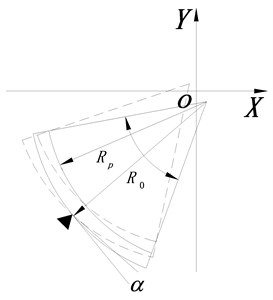
Furthermore, the swing of pad shown in Fig. 4 should also be taken into account in derivation of mathematical model of the tilting pad journal bearings.
Fig. 3Sketch map of the 4-tilting-pad journal bearings
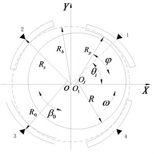
Fig. 4Sketch map of a single pad
Equation of the swing of pad is:
where is moment of inertia of the pad, is angular acceleration, is moment:
Eq. (13) and Eq. (14) are combined to be mathematical expression of the tilting pad journal bearings, which will be adopted in the following research. Furthermore, linear and nonlinear dynamic characteristics and parametric sensitivity of the model should be studied primarily.
3. Characteristics of oil-film force
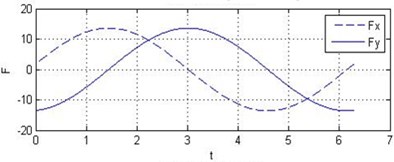
In order to illustrate the distinction between the conventional plain bearing and the tilting pad journal bearings, it is assumed that the journal whirls with a radius of 0.01 mm. Thus the coordinate of the journal’s center can be expressed as:
It is assumed that the conventional plain bearing and the tilting pad journal bearings are with the same parameters such as radius, length, width and viscosity of oil. Fig. 5 shows the result of numerical analysis. It can be observed that the tilting pad journal bearings produce higher oil-film force than the conventional one does.
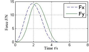
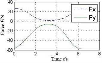
The oil-film force produced by the conventional plain bearing can be divided into four parts along the circular in order to compare with 4 pads of the tilting pad journal bearings, as illustrated in Fig. 6. It can be concluded that every pad of the tilting pad journal bearings provides positive oil-film force at any time, while there are several intervals with 0 oil-film force in the conventional one. The tilting pad journal bearings produce higher oil-film force and is more stable.
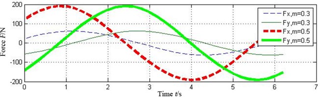
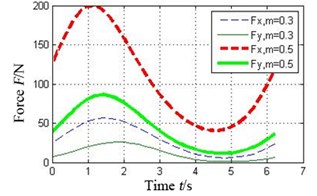
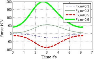
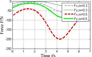
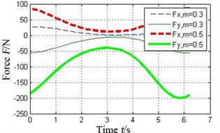
Fig. 7 shows the oil-film force produced by the tilting pad journal bearings with different preload coefficients , . It can be seen that the bigger the preload coefficient is, the more severe variation of oil-film stiffness is. As a result higher oil-film force will produce.
Fig. 5Comparison of oil-film forces of the conventional plain bearing and the tilting pad journal bearings
a) Oil-film force of the conventional plain bearing
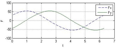
b) Oil-film force of the tilting pad journal bearings
Fig. 6a) Oil-film force in 4 conjoint parts of the conventional plain bearing and b) in different pad of the tilting pad journal bearings
a1) Part 1
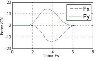
a2) Part 2
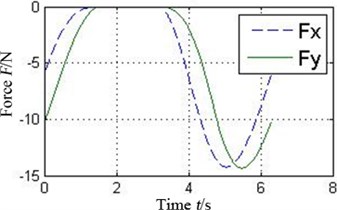
a3) Part 3
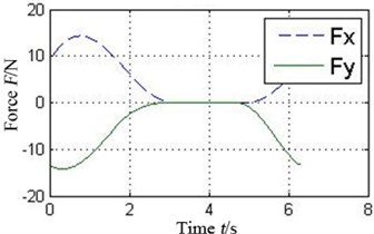
a4) Part 4
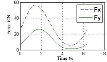
b1) Pad 1
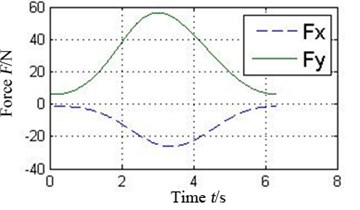
b2) Pad 2
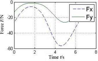
b3) Pad 3
b4) Pad 4
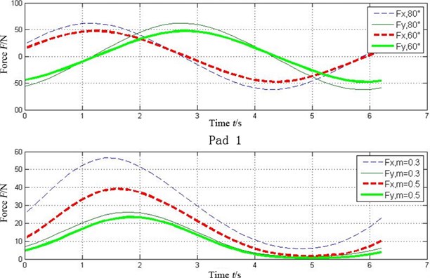
Fig. 8 illustrates the oil-film force with different wrapping angles 60°, 80°. It is clear that the larger one leads to the higher force.
Fig. 9 shows effect of the swing angle on the oil-film force. The outer part stands for the range of the swing angle and the inner one is . It can be deduced that the bigger the range of the swing angle is, the greater the oil-film force is.
Analysis on the swing of pad is illustrated in Fig. 10. It can be seen that the pad keeps swinging when the journal is rotating. From FFT spectrum map it can be concluded that the swing of pad will produces 0.3 octave frequency, which is similar with the oil-film whirl of the conventional plain bearing. This result is coincident with Adams and Payandeh [20].
Fig. 7Effect of preload coefficient on oil-film force of the tilting pad journal bearings
a)
b) Pad 1
c) Pad 2
d) Pad 3
e) Pad 4
Fig. 8Effect of wrapping angle on oil-film force of the tilting pad journal bearings
4. Linear dynamic characteristics of the double cantilever rotor system
The double cantilever rotor system can be modeled as four discs and three shafts [1], as shown in Fig. 11. The wheels and the bearings can be abstracted as discs, and the shafts can be considered as being connection with stiffness and without mass.
Fig. 9Pressure distribution on the pad based on two different pad angles
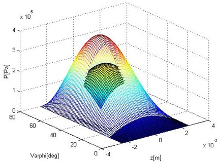
Fig. 10Time waveform plot and FFT spectrum of the tilting pad
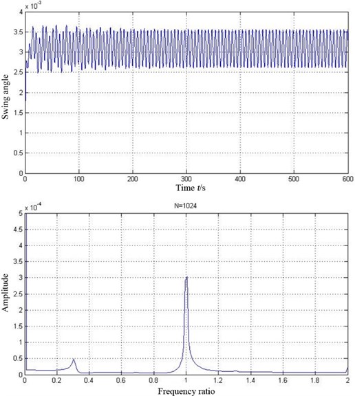
Fig. 11Lumped masses model of the double cantilever rotor system
The mathematical expression of the simplified model is as follows:
therefore, the double cantilever rotor system can be elaborated as:
This matric equation is suitable for further analysis of modal and critical speed using transfer matrix method. Table 1 lists parameters of the double cantilever rotor system.
Table 1Physical and geometrical parameters of the double cantilever rotor system
Parameters | Value |
Mass | 2.37 kg, 3.0 kg, 3.0 kg, 2.4 kg |
Inertia | 4.9×10⁻³ kg·m2, 1.3×10⁻² kg·m2 1.0×10⁻² kg·m2, 3.1×10⁻³ kg·m2 1.0×10⁻² kg·m2, 3.1×10⁻³ kg·m2 3.7×10⁻³ kg·m2, 1.0×10⁻² kg·m2 |
Young’s modulus | 205 GPa |
Length of shaft | 255 mm, 460 mm, 255 mm |
Radius of shaft | 33 mm, 65 mm, 33 mm |
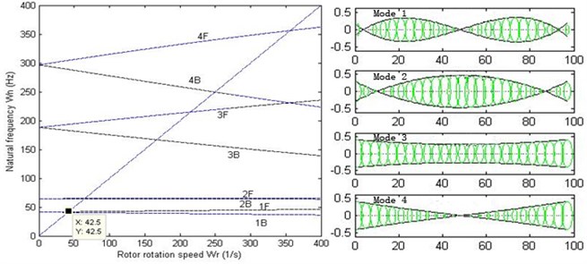
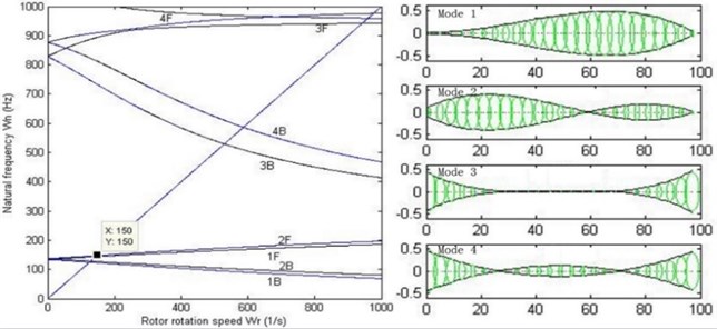
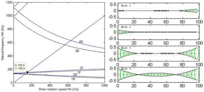
For analysis of modal and critical speed, the stiffness of the oil-film needs to be linearized. Without loss of generality, linear stiffness 106, 108, 1010 N/m are chosen. When dealing with the critical speed of the rotor system, Campbell diagram is used. As shown in Fig. 12, Campbell diagram and 1st-4th order modes with different stiffness are illustrated.
It can be concluded that the critical speed of the double cantilever rotor system increases as the stiffness of the bearings increases, and the shapes of 1st-4th order modes also vary. When 106 N/m, 1st and 2nd order modes appear to be rigid movement because the relatively low stiffness does not have enough restraint on the vibration of the rotor system. When 108 N/m, the modes appear to be bending ones. However, when 1010 N/m, 3rd and 4th order modes turn into local ones. Fig. 13 illustrates the relationship between 1st and 2nd forward and backward critical speed versus the stiffness of the bearings. It can be seen that the critical speeds remain unchanged when the stiffness reaches about 108.5 N/m, which means that the double cantilever rotor system is over restricted by the bearings. Therefore, the stiffness 108 N/m and 1st order critical speed rad/s are chosen for the following work, and the value is basically in agreement with behavior of a certain type of turbo expander in application.
Fig. 12Campbell diagram and first 4-order mode of the rotor system with various bearings stiffness
a)106 N/m
b) 108 N/m
c)1010 N/m
5. Nonlinear dynamic characteristics of the double cantilever rotor system on the tilting pad journal bearings
Eq. (13) for the oil-film force of the tilting pad journal bearings is highly nonlinear, so it is impossible to deal with the rotor dynamic model of the double cantilever rotor supported by the tilting pad journal bearings using matrix analysis. A system of ordinary differential equations should be derived in order to obtain stable time-domain solution using numerical method for further analysis. Suppose:
then a nondimensionalized system of the ordinary differential equations can be derived:
The swing of pad should also be taken into account:
Table 2 lists physical and geometrical parameters of the rotor system.
Fig. 13Curve diagram of critical speed of the rotor system versus bearings stiffness
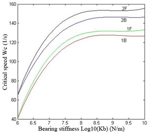
Table 2Physical and geometrical parameters of test rotor and the tilting pad bearings
Parameter | Value | |
Rotor | Imbalance | 0.005 mm |
Damping ratio | 0.01 | |
1st critical speed | 2×150 rad/s | |
Bearing | Machining clearance | 0.06 mm |
Installation clearance | 0.045 mm | |
Preload | 0.25 | |
Inertia of pads | 2.19×10⁻⁵ | |
Number of pads | 4 | |
Wrapping angle | 72° | |
Position angle of pivot | 45°, 135°, 225°, 315° | |
Length of bearing | 30 mm | |
Diameter of bearing | 60.09 mm | |
Oil | Viscosity | 0.027 Pa·s |
The following nonlinear analysis is based on the equations and the parameters stated previously.
A bifurcation diagram is quite useful for acquiring the nonlinear dynamic characteristics of a rotor system with a certain parameter variation. For a bearings-rotor system, the rotating speed is the most important element which has a great influence on its behavior. In this study, the vibration of the right wheel in direction is chosen for plotting the bifurcation diagram. Fig. 14 illustrates the diagram along with the rotating speed ratio 0.67-2.33 and a zoomed diagram with 1.4-1.6. It can be seen that the double cantilever rotor system bifurcates at 1.46 and enters period-2 motion from period-1. After that, the rotor system follows period motion and quasi-period motion alternately.
Fig. 14Bifurcation diagram of the rotor system with variation rotating speed
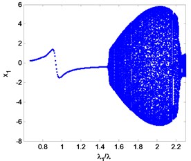
a)0.67-2.33
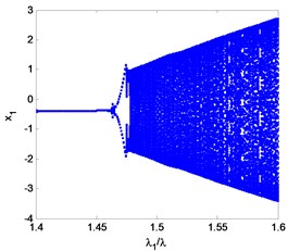
b)1.4-1.6
Fig. 15Time waveform plot, FFT spectrum, orbit of disc center and Poincaré map at rotating speed ωr= 2π×130 rad/s, (λ= 0.87)
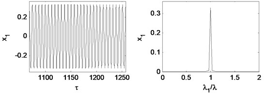
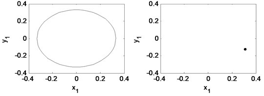
Fig. 16Time waveform plot, FFT spectrum, orbit of disc center and Poincaré map at rotating speed ωr= 2π×220.5 rad/s, (λ= 1.47)
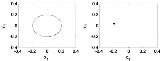
Fig. 15 is time waveform plot, FFT spectrum, orbit of disc center and Poincaré map when 0.87. It is shown that the motion appears period-1.
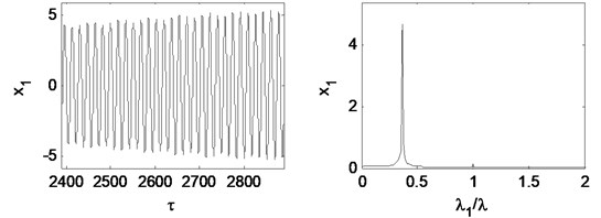
Fig. 16 is time waveform plot, FFT spectrum, orbit of disc center and Poincaré map when 1.47. The oil whirl happens at this rotating speed that 0.5 octave frequency component occurs, the orbit of disc center is no longer a circle, and the Poincaré map appears to be two points, which are all symptom of period-2 motion.
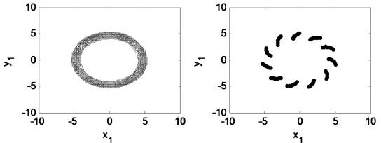
The oil whip happens at 1.67 as shown in Fig. 17. Herein, fundamental frequency is no longer the dominant frequency component and the whirl frequency component increases. The orbit of the disc center and the Poincaré map become complicated. The motion of the double cantilever rotor system appears to be quasi-periodic.
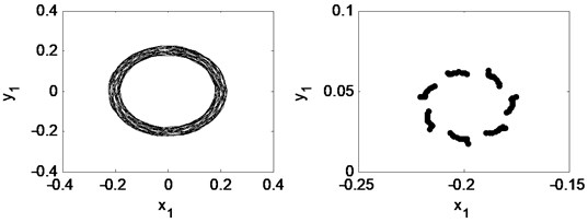
Fig. 17Time waveform plot, FFT spectrum, orbit of disc center and Poincaré map at rotating speed ωr= 2π×250 rad/s, (λ= 1.67)
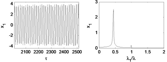
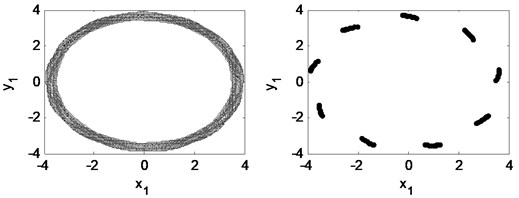
Fig. 18Time waveform plot, FFT spectrum, orbit of disc center and Poincaré map at rotating speed ωr= 2π×350 rad/s, (λ= 2.33)
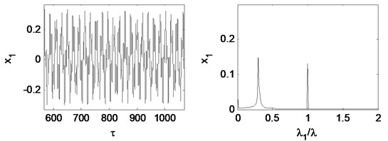
When the rotating speed reaches 2.33, as Fig. 18 illustrates. The vibration becomes extremely complex. The Poincaré map indicates that the motion of the system is quasi-periodic. The whirl frequency does not continue decreasing and keeps at about 0.3 octave frequency, which is called frequency-locked. Fig. 19 shows that the waterfall plot, the frequency-locked can be identified intuitively.
From the research above, it can be concluded that the rotating speed has great effects on the nonlinear characteristics of the double cantilever rotor system, and the most important factor is the oil whirl or the oil whip produced by the tilting pad journal bearings.
Fig. 19Waterfall plot
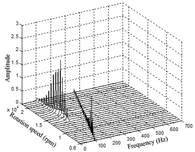
Fig. 20Bifurcation diagram of the rotor system with eccentricity
a) 2×200 rad/s, ( 1.33)
b) 2×300 rad/s, ( 2.0)
Fig. 21Time waveform plot, FFT spectrum, orbit of disc center and Poincaré map at eccentricity 1×10⁻⁵ m and the rotating speed ωr= 2π×200 rad/s, (λ= 1.33)
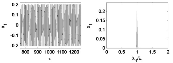
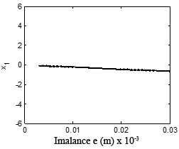
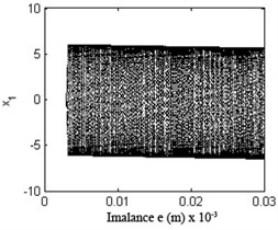
Eccentricity is one of the main sources of a turbo expander’s vibration and is important to the response of the plant’s vibration. Fig. 20 shows the bifurcation diagram under different rotating speeds. Fig. 21 and Fig. 22 illustrate the time waveform plot, FFT spectrum, orbit of disc center and Poincaré map. In Fig. 20 a), the rotor system remains period-1 motion no matter how large the eccentricity is, because when 1.33 there is no oil-whirl or oil whip. However, in Fig. 20(b), the rotor system keeps quasi-periodic motion no matter how large the eccentricity is because of the oil whirl at 2.0.
Fig. 22Time waveform plot, FFT spectrum, orbit of disc center and Poincaré map at eccentricity 1×10⁻⁵ m and the rotating speed ωr= 2π×300 rad/s, (λ= 2.00)
It can be concluded that the eccentricity have no influence on the motion type of the double cantilever rotor supported by the tilting pad journal bearings. The oil-whirl or the oil-whip dominates the behavior of the system.
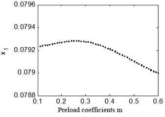
The preload coefficient has a great influence on the dynamic behaviors of the bearings-rotor system. Fig. 23 shows bifurcation diagram with the preload coefficients 0.67 and 1.33. It can be seen in a) that the rotor system keeps peiod-1 motion no matter how large the preload coefficient is, in b) the system is under quasi-periodic motion when the preload coefficient is below about 0.2.
Fig. 23Bifurcation diagrams of the rotor system with TPJB preload coefficient
a) 2×100 rad/s, ( 0.67)
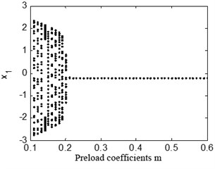
b) 2×200 rad/s, ( 1.33)
Fig. 24 and Fig. 25 illustrate time waveform plot, FFT spectrum, orbit of disc center and Poincaré map with 1.33 when 0.15 and 0.21 respectively. It can be seen that when m is less than 0.2, the 0.5 octave oil whirl frequency is larger than the fundamental frequency. When m is larger than 0.2, the fundamental frequency recovers to be dominant, and the rotor system performances period-1 motion. It can be concluded that when the rotating speed is under 1st critical speed, the preload coefficient has no influence on the motion type of the rotor system. When 1st critical speed is surpassed, the preload coefficient can bring forward the oil whirl if it is small enough.
Fig. 24Time waveform plot, FFT spectrum, orbit of disc center and Poincaré map at TPJB preload m= 0.15 and the rotating speed ωr= 2π×200 rad/s, (λ= 1.33)
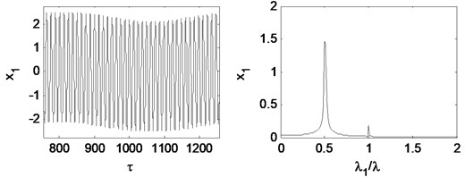
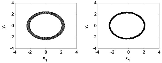
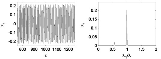
Fig. 25Time waveform plot, FFT spectrum, orbit of disc center and Poincaré map at TPJB preload m= 0.21 and the rotating speed ωr= 2π×200 rad/s, (λ= 1.33)
6. Conclusions
A mathematical expression of the 4-tilting-pad journal bearings considering the oil cavitation and the swing of pad is established. The oil-film force produced by the bearings is larger than the conventional plain bearing. The titling-pad journal bearings is more stable for its better oil-film force distribution.
The linear dynamic model of the double cantilever rotor is built, whose mode and critical speed are studied. It can be concluded that the critical speed keeps increasing when the supporting stiffness becomes larger. However, when the stiffness reaches about 108.5 N/m, the critical speeds almost remain unchanged.
The model of the tilting pad journal bearings supporting the double cantilever rotor is built using previously established the oil-film force, the nonlinear characteristics are studied. The oil whirl and the oil whip are the main sources which lead to the motion type transforming. The eccentricity has little influence on the motion type and the preload coefficient is effective when 1st order critical speed is surpassed.
References
-
Ying G., Meng G., Jing J. Turbocharger rotor dynamics with foundation excitation. Archive of Applied Mechanics, Vol. 79, 2009, p. 287-299.
-
Jing J.-P., Li J.-Z., Liu X.-Q., Li D.-S., Meng G. Nonlinear dynamical behaviors of a cracked turbocharger rotor system with base excitation. International Journal of Nonlinear Sciences and Numerical Simulation, Vol. 10, 2009, p. 563-580.
-
Tian L., Wang W., Peng Z. Dynamic behaviours of a full floating ring bearing supported turbocharger rotor with engine excitation. Journal of Sound and Vibration, Vol. 330, 2011, p. 4851-4874.
-
Li M., Wang Y., Li F., Li H., Meng G. Modelica-based object-orient modeling of rotor system with multi-faults. Chinese Journal of Mechanical Engineering, Vol. 26, 2013, p. 1169-1181.
-
Li F. C., Peng H. K., Meng G. Quantitative damage image construction in plate structures using a circular PZT array and lamb waves. Sensors and Actuators A-Physical, Vol. 214, 2014, p. 66-73.
-
Li F. C., Meng G., Ye L., Lu Y., Kageyama K. Dispersion analysis of lamb waves and damage detection for aluminum structures using ridge in the time-scale domain. Measurement Science and Technology, Vol. 20, 2009, p. 1-10.
-
Rimpel A. M., Moore J. J., Grieco J. S., Shy P. C., Klein J. M., Brady J. L. Rotordynamics of a 105,000 rpm oil-free compressor-expander for subsurface natural gas compression and reinjection. ASME Turbo Expo 2012: Turbine Technical Conference and Exposition, American Society of Mechanical Engineers, 2012, p. 753-766.
-
Boyd J., Raimondi A. An analysis of the pivoted-pad journal bearing. Mechanical Engineering, Vol. 75, 1953, p. 380-386.
-
Lund J. Spring and damping coefficients for the tilting pad journal bearing. ASLE Transactions, Vol. 7, 1964, p. 342-352.
-
Nicholas J., Gunter E. J., Allaire P. E. Stiffness and damping coefficients for the five-pad tilting pad bearings. ASLE Transactions, Vol. 22, 1979, p. 113-124.
-
Orcutt F. The steady-state and dynamic characteristics of the tilting pad journal bearing in laminar and turbulent flow regimes. Journal of Lubrication Technology, Vol. 89, 1967, p. 392-400.
-
Parsell J., Allaire P., Barrett L. Frequency effects in tilting pad journal bearing dynamic coefficients. ASLE Transactions, Vol. 26, 1983, p. 222-227.
-
Barrett L., Allaire P., Wilson B. The eigenvalue dependence of reduced tilting pad bearings stiffness and damping coefficients. Tribology Transactions, Vol. 31, 1988, p. 411-419.
-
Lund J. W., Pedersen L. B. The influence of pad flexibility on the dynamic coefficients of a tilting pad journal bearing. Journal of Tribology, Vol. 109, 1987, p. 65-70.
-
Earles L., Armentrout R., Palazzolo A. A finite element approach to pad flexibility effects in tilt pad journal bearings: part I – single pad analysis. Journal of Tribology, Vol. 112, 1990, p. 169-176.
-
Earles L., Armentrout R., Palazzolo A. A finite element approach to pad flexibility effects in tilt pad journal bearings: part II – assembled bearing and system analysis. Journal of Tribology, Vol. 112, 1990, p. 178-182.
-
White M., Chan S. The subsynchronous dynamic behavior of tilting pad journal bearings. Journal of Tribology, Vol. 114, 1992, p. 167-173.
-
Yang P., Rodkiewicz C. On the numerical analysis to the thermoelastohydrodynamic lubrication of a tilting pad inclusive of side leakage. Tribology Transactions, Vol. 40, 1997, p. 259-266.
-
Dimond T., Younan A. A., Allaire P., Nicholas J. Modal frequency response of a four-pad tilting pad bearings with spherical pivots, finite pivot stiffness, and different pad preloads. Journal of Vibration and Acoustics, Vol. 135, Issue 4, 2013, p. 1-11.
-
Adams M., Payandeh S. Self-excited vibration of statically unloaded pads in tilting pad journal bearings. Journal of Lubrication Technology, Vol. 105, 1983, p. 377-383.
About this article
The authors are grateful for the support received from the National Basic Research Program of China (973 Program, No. 2011CB706502).
