Abstract
The paper presents the model and design of a flexure-based 4 DOF precision positioning system for micro-positioning uses. The positioning system is featured with monolithic architecture, flexure-based joints and ultra-fine adjustment screws. The monolithic structure for the require movements has been optimized with Solidworks Simulation software package. The mathematical model for the output displacements of the positioning system has been verified by resorting to finite element analysis (FEA) using ANSYS software package. The established analytical and (FEA) models are helpful for a reliable architecture optimization and performance improvement of the precision positioning systems.
1. Introduction
Positioning with nanometre level resolution and accuracy is critically important for many modern technologies, especially in the fields of micro and nanotechnology. Ultra precision positioning systems are widely used in various applications, such as optical alignment, scanning probe microscope, precision manufacturing and measurement systems. Various micro-motion stages have been developed using conventional technologies based on servomotors, ball screws and rigid linkages. However, these conventional technologies encounter problems like friction, wear, backlash and lubrication that struggle to achieve high positioning accuracy. Stick-slip friction, sometimes known as dry friction, is a well-known problem in the ultra precision positioning system with nanometre resolution. Assembly errors are also an extensive problem in the ultra precision positioning system. The asymmetric structure of the system makes it sensitive to thermal strain errors that require high cost to compensate.
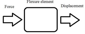
Flexures are the best choice to overcome these problems. Micro-motion stages utilizing the flexure hinge mechanism can have many advantages like negligible backlash and stick-slip friction, smooth and continuous displacement adequate for magnifying or reducing the output displacement of actuation and inherently infinite resolution. A monolithic structure is required to eliminate assembly errors. A symmetric structure can reduce the effect of thermal strain error. The term “flexure” embraces a number of positioning devices which rely upon the elastic deformation of solid materials, as shown in Fig. 1. A flexure may be as small as a quartz fibre or have a thickness of several millimetres. The principle aim is to achieve low stiffness in the direction of the required motion and high stiffness in all other directions without introducing undue stress and friction [1-8].
Fig. 1Principle of flexure element
There have been a few modelling studies for the analysis and design of the monolithic flexure hinge mechanisms. Paros’ model [9] was developed to calculate spring rates of a single-axis flexure hinge mechanism. However its application was limited to one hinge itself not to a system. There have also been researches on design formulae [10], and methodology [11] of the monolithic flexure hinge mechanism. Their applications were very specific. A more generalized model to estimate the elasticity, natural frequency, and dynamic characteristics of an assembly of flexure hinges was developed by Tanaka [12]. Furthermore, a finite element method (FEM) was also used for the design and analysis of the flexure hinge mechanism. A computer based method that automatically generates equations of motion for the flexure hinge mechanism was recently presented. The method also solves the generated equations numerically to predict the static characteristics of the hinge flexure mechanism.
This paper proposes a novel 4 DOF precision positioning system on the rotational platform for calibration of the rotary encoder’s raster scales. The system is featured with flexure-based joints and mechanical actuation. The flexure-based joints for required motion were optimised and their performances in terms of workspace, maximum stress, resonant frequency have been evaluated by finite element analysis approach, using ANSYS software package.
2. Working principle
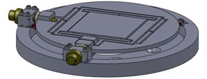
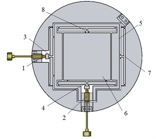
The positioning system, as shown in Fig. 2, consists of an external ring (base) having mounted centring-tilting adjustment elements and a monolithic structure for centring adjustment. The base and monolithic structure of centring adjustment are jointed with compliant mechanisms – flexure hinges. Cantering-tilting adjustment is equipped in the two points of the same plane, in the two, one other perpendicular axes.
The angle between two adjustable tilting flexure hinges is 90° and the fixed flexure hinge is equipped in the symmetrical axis between these flexure hinges.
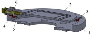
Fig. 24 DOF precision positioning system a) general view; b) section view: 1 – external ring (base), 2 – monolithic structure (centring platform), 3 – fixed flexure hinge, 4 – adjustable flexure hinge, 5 – ultra fine adjustment screw, 6 – cam mechanism
a)
b)
The positioning system uses manual adjusters similar to micrometers to provide motion, as shown in Fig. 3. These high precision adjusters avoid all complications associated with hydraulic and pneumatic drivers or electronic actuators.
To operate tilting adjustment a cam mechanism was chosen. The adjustment range of the cam is 100 µm. The handy dimensions of tilting knobs are optimally chosen to feel rotation as little as 0.5°-1°. This enables to achieve the positioning sensitivity of 0.3 μm.
To operate centring adjustment an ultra-fine adjustment screws was chosen, see Fig. 3. Ultra-fine adjustment screws are compact and provide extremely high resolution. Special design provides smooth and repeatable action by mating a high precision pitch of 200 µm and a stainless steel screw with a high precision brass collar. The screws have a hardened steel ball on the tip. The mounting surface of collars is plain cylindrical. The handy dimensions of the knobs are optimally chosen to feel rotation as little as 0.5°-1°. This enables to achieve the positioning sensitivity of 0.5 μm. Axial load capacity noted of manufacturer is 70 N.
The centring platform consists of and motion stages. Each and stage consists of a reduction mechanism of motion and a guide mechanism of motion. The stage has the same structure except that it is inside the stage. and motion is decoupled. Generally, a decoupled stage implies that one adjuster produces only one directional output motion without affecting the motions in other axes. The major objective for the design of a stage with decoupled output motion is to eliminate the cross-axis coupling errors between the and directional translations and parasitic rotation errors around the axes. The motion reduction mechanism that is proposed in this system has a merit. Its symmetric lever mechanism structure makes the stage robust to heat.
Ultra-fine adjustment screw 1 through motion reduction mechanism 3 deflects -axis moving platform 5 and guide mechanism 7 limit rotation about axis, therefore ultra-fine adjustment screw 2 through motion reduction mechanism 4 deflects -axis moving platform 6 and guide mechanism 8 limit rotation about axis.
Fig. 3Centring-tilting mechanism
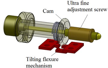
Fig. 4Monolithic structure (centring platform): 1, 2 – ultra-fine adjustment screws; 3, 4 – motion reduction mechanisms; 5 – x axis moving platform; 6 – y axis moving platform; 7, 8 – guide mechanisms
3. Flexure design
The flexure hinge which is one of the compliant mechanisms and a symmetric structure is used in ultra precision positioning system. Functionally, the ideal flexure hinge permits limited relative rotation of the rigid adjoining members while prohibiting any other types of motion. The typical flexure hinge consists of one or two cut outs that are machined in a blank material. Flexure hinge is classified into four types, such as symmetric circular, elliptic, parabolic and hyperbolic flexure hinges. A physical bending point is generated at a maximum stress point. The flexure hinge has the highest accuracy, when the bending point is located in the centre of the hinge [7].
A symmetric circular flexure hinge has the bending point in the centre of the hinge. Therefore, a symmetric circular flexure hinge is suitable for ultra precision positioning system.
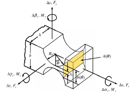
In Fig. 5, the relevant coordinate system and parameters of a circular hinge are shown. Important design properties for any type of flexure hinge are stiffness in rotation direction , stiffness in - and -direction and the stress build up due to bending (elastic deformation) over an angle [7].
Fig. 5Circular flexure hinge
Aluminium alloy and steel are often used as base materials of flexure hinges. In the analysis, aluminium alloy Al 7075-T6 is used because it has small elastic modulus and high yield strength. To ensure the machining precision of the stage, the flexible hinges were machined using an electro-discharge machining (EDM) technique.
4. Workspace analyses and analytical model simplification approach of the centring platform
The workspace of the centring platform is primarily defined by the range of motion permitted by its joints and the displacement produced by its actuators, in this case the elastic range of flexure hinges and the elongation of actuators. Thus, the problem of workspace analysis can be cast completely in terms of constraints due to allowable rotation and translation range at flexure hinges. The angular compliance of the flexure hinge has been calculated using Paros and Weisbord equation [10]:
Rotational stiffness is:
Translational compliance is:
Translational stiffness is:
where:
– the Young’s modulus of the material of the flexure hinge, – the angular deformation of the hinge about the -axis in radians, – external bending torque applied to the hinge with a possibility determining the allowable rotational range, – the linear deformation of the hinge in the direction of the -axis and – external translation force applied to the hinge with a possibility determining the allowable translational range.
The maximum bending torque is equal to:
The maximum force that can be applied to the flexure hinge is:
where:
is the smallest moment of the inertia of the flexure hinge about the rotation axis; – the smallest area of the flexure hinge, , – stress limit is the proportional limit of a ductile material or the fracture strength of a brittle material.
Thus, the limit of rotational and the translational range to the flexure hinge are:
While operating at this stage, the angular and linear deformations of flexure hinges must always be kept within this limit. The flexure hinges used on the stage are single-axis flexure hinges, as shown in Fig. 5, where 0.3 mm; 0.75 mm; 3 mm; 3 mm. The Young’s modulus of Al 7075 T-6 aluminium alloy is 72 GPa and its proportional limit is 505 MPa. Thus, for all flexure joints on the stage rotational stiffness:
and translational stiffness:
Limit to rotational range:
Limit to translational range:
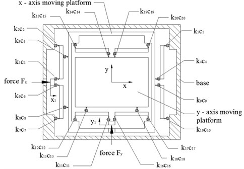
By replacing each flexure hinge with two degrees of freedom, a revolute and translation joint with a linear and torsion spring while considering the remainder elements as rigid bodies, the analytical model of the dual axis centring platform is established as shown in Fig. 6.
We can observe that the dual axes stage consists of twenty elastic elements – flexure hinges, which are designed to have the identical dimensions as elaborated in Fig. 5 and thirteen rigid bodies. Due to the motion of the stage in and axes is independent, we can assume, that the motion in and axis is equal and further we can analyze only the motion of one axis. Whereas one axis motion stage is symmetric we can analyze only half stage, as shown in Fig. 7(a), (b).
Fig. 6Model of centring platform
The potential energy of the linear system:
where the angular displacements of the beams in Fig. 7(a):
The potential energy of the centring positioning platform is:
Fig. 7Mathematical model of the 4 DOF precision positioning system: a) generalised coordinates; b) stiffness and damping coefficients
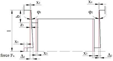
a)
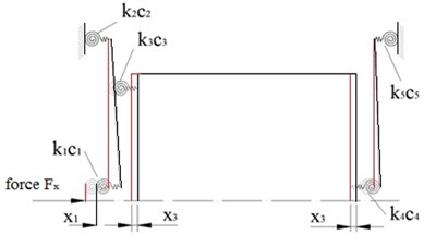
b)
The application of Lagrange’s equation for:
The generalized potential force:
Derived equations are written in matrix form as:
Matrix solutions:
5. Model verification FEM
The designed 4 DOF precise positioning system was verified by FEM. The finite element analyses were performed using “ANSYS 14.0” software package.
The simulation of tilting adjustment includes two conditions – the maximum stroke and the minimum resolution of the cam are simulated. When the maximum stroke is 100 µm, the maximum displacement of the centring platform is 76.7 µm. The maximum value von Misses stress is 368.57 MPa, which is 72.98 % of the yield strength of aluminium alloy 7075 T-6 of the material. When the minimum capable resolution is 0.5 µm, the maximum displacement of the centring platform is 0.38 µm.
The simulation of centring adjustment includes two conditions, – the maximum capable stroke of the stage and the resolution of the ultra fine adjustment screw are simulated.
A finite element analysis indicates that when the and motion adjusters deflects 400 µm the von misses stress values are 509.57 MPa and 512.86 MPa, respectively. To prevent the monolithic structure to plastically deforming in this scenario the input displacement was limited to 350 µm.
Recall that the load capacity of the manual adjusters is 70 N. To avoid damaging the adjusters, the service load on the adjusters is kept below 70 N. When the manual adjuster is extended to move the and motion platforms 350 μm, the compressive forces are 63.1 N and 64.5 N, respectively.
Fig. 84 DOF precision positioning system divided into finite elements
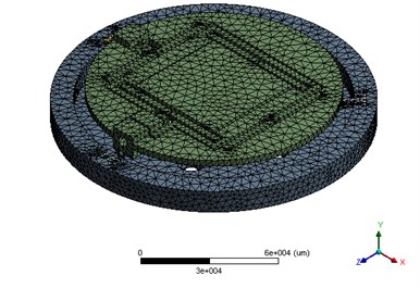
Fig. 94 FEM simulation of centring: a) x motion; b) y motion
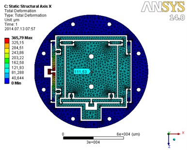
a)
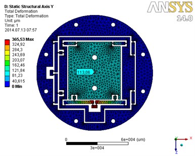
b)
Input displacement, – the stroke of 350 μm was applied to axis direction, the moving platform deflects 111.53 μm, as shown in Fig. 9(a). The maximum von misses stress value is 415.3 MPa, which is 82.2 % of the yield strength of aluminium alloy 7075 T-6 of the material. When capable resolution of 0.5 μm was applied to axis direction, the moving platform deflects 0.160 μm. When the stroke of 350 μm was applied to axis direction, the moving platform deflects 113.06 μm, as shown in Fig. 9(b). The maximum von misses stress value is 343.1 MPa, which is 70.0 % of the yield strength of aluminium alloy 7075 T-6 of the material. When input displacement of 0.5 μm was applied to axis direction, the moving platform deflects 0.162 μm. The reduction ratios of the motion and motion platforms are 0.319 and 0.323, respectively.
The natural frequencies and the dynamic behaviour of the 4 DOF precise positioning system are crucial aspects for its successful use in micro/nanomanufacturing. The stage should be designed to respond quickly to the fast changes in the adjusted position but needs to be robust at the same time. The stage will respond uniquely at the natural frequencies with different mode shapes. In order to further examine dynamic performance of the 4 DOF precise positioning system described above, finite element analysis is conducted to perform dynamic investigation.
In the simulation, with the material parameters assigned and the mesh model created, the bottom surface of the base are fixed with zero displacements to immobilize the mechanism.
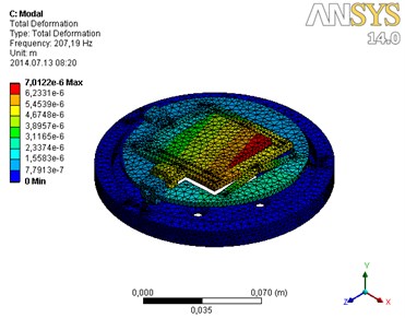
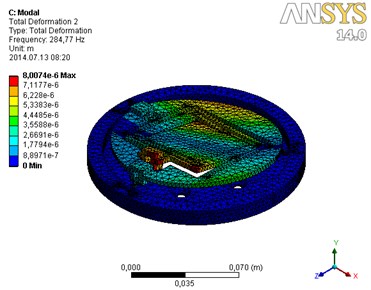
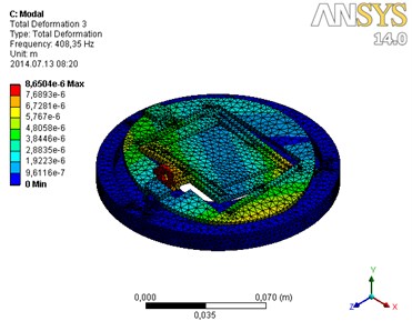
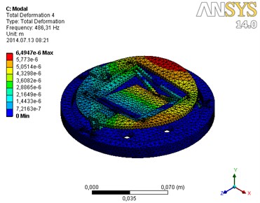
Fig. 10 shows the first-fourth order mode shape of the 4 DOF precise positioning system. The first-fourth modes of the mechanism without adjusters were generated at 207.2 Hz, 284.8 Hz, 408.4 Hz and 486.3 Hz, as shown in Fig. 10(a), (b), (c) and (d), respectively.
Fig. 10Modal analysis of a 4 DOF precision positioning system without load: a) first mode; b) second mode; c) third mode; d) fourth mode
a)
b)
c)
d)
6. Results and discussions
The input displacement of the adjusters according to desired output displacement is shown in Table 1. Some variation exists in the results, for instance, when applied maximum displacement of centring the difference between analytical model and FEM motion results is 3.0 % and the difference between analytical model and FEM motion results is 1.7 %. When applied minimum displacement of centring the difference between analytical model and FEM motion results is 3.0 % and the difference between analytical model and FEM motion results is 1.8 %. The difference of the reduction ratio between analytical and FEM motion results is 3.0 % and between analytical and FEM motion results is 1.8 %.
Table 1Static analysis results
Analysis method | Input data | Reduction ratio (Average) | |
350 μm | 0.5 μm | ||
Analytical | 114.98 | 0.165 | 0.329 |
FEM, motion | 111.53 | 0.160 | 0.319 |
FEM, motion | 113.06 | 0.162 | 0.323 |
Difference FEM ()/Analytical, % | 3.0 | 3.0 | 3.0 |
Difference FEM ()/Analytical, % | 1.7 | 1.8 | 1.8 |
7. Conclusions
This paper proposes the novel flexure based 4 DOF precision positioning system for micro positioning. In this work analytical approach of centring motion for displacement and stiffness calculation is presented. On the base of the analytic expressions of potential energy included in Lagrange’s equations, the numerical expressions of transfer functions of the centring motion are generated. The workspace of centring motion is 114.98×114.98 μm by analytical and 111.53×113.53 μm by FEM. The calculated analytical results have a good match with FEA results, therefore the proposed analytical approach and methodology can be applied to the modelling of other types of flexure based precise positioning stages, as well. In addition, the proposed positioning system possesses configurationally simplicity and compactness.
References
-
Meng Q., Li Y., Xu J. A novel analytical model for flexure-based proportion compliant mechanisms. Precise Engineering, 2014, p. 9, (in press).
-
Zhang D., Gao Z., Malosio M., Coppola G. Analysis of the novel flexure parallel micromanipulators based on multi-level displacement amplifier with/without symmetrical design. International Journal of Mechanics and Materials in Design, Vol. 8, 2012, p. 311-325.
-
Bhagat U., Shirinzadeh B., Clark L., Chea P., Qin Y., Tian Y., Zhang D. Design and analysis of a novel flexure-based 3-DOF mechanism. Mechanism and Machine Theory, Vol. 74, 2014, p. 173-187.
-
Xu Q. A novel compliant micropositioning stage with dual ranges and resolutions. Sensors and Actuators A, Vol. 205, 2014, p. 6-14.
-
Qina Y., Shirinzadehb B., Zhanga D., Tiana Y. Compliance modeling and analysis of statically indeterminate symmetric flexure structures. Precision Engineering, Vol. 37, 2013, p. 415-424.
-
Augustaitis V. K., Gican V., Sesok N., Iljin I. Computer-aided generation of equations and structural diagrams for simulation of linear stationary mechanical dynamic systems. Mechanika, Vol. 17, Issue 3, 2011, p. 255-263.
-
Lobontiu N. Compliant Mechanisms: Design of Flexure Hinges. CRC press. London, 2003.
-
Augustinavičius G., Čereška A. Modelling of a 4DOF precise positioning stage by finite element method. Mechanika, Vol. 17, Issue 1, 2011, p. 8-11.
-
Paros J. M., Weisbord L. How to design flexure hinge. Machine Design, Vol. 37, 1965, p. 151-157.
-
Furukawa E., Mizuno M., Hojo T. A twin-type piezo-driven translation mechanism. Precision Engineering, Vol. 28, Issue 1, 1994, p. 70-75.
-
Smith S. T., Chetwynd D. G., Bowen D. K. Design and assessment of monolithic high precision translation mechanisms. Review of Scientific Instruments, Vol. 20, 1988, p. 977-983.
-
Tanaka M. The dynamic properties of a monolithic mechanism with notch flexure hinges for precision control of orientation and position. Japanese Journal of Applied Physics, Vol. 22, Issue 1, 1983, p. 193-200.
About this article
