Abstract
High-speed gas bearings for turbomachinery can dramatically improve the isentropic efficiency of turbine plants. Vibrations, especially low-frequency vibrations caused by the gas-film self-excited vibrations, significantly affect the safety and economy of the turbomachinery, which is dangerous at high rotational speeds. This experimental study focuses on the dynamic characteristics of a flexible rotor supported by gas hybrid bearing and driven by a radial turbine with high-pressure air. Cylindrical whirling, conical whirling, and first-order bending natural frequencies that change with bearing supply pressures were obtained by experimental modal analysis. Nonlinear mechanic behaviors, including gas film half-speed whirling and gas-film whip, in the experiments were identified by nonlinear measurements and analyses. The occurrence mechanism of gas-film whirling and whip is also discussed in this paper. Experiments for eliminating and restraining whirling and whip were conducted to investigate the gas bearing-rotor system stability effect of bearing supply pressure and elastic foundation. Some simple and effective measures were given to improve the stable rotational speed.
1. Introduction
With the development of high-speed micro-turbine equipment for output power from thousands of watts to hundreds of kilowatts, the requirements for the durability and stability of the rotor-bearing system in high-speed micro turbine equipment are becoming increasingly crucial to achieve high performance and long service. The gas bearings in high-speed micro turbines have the advantages of high-movement accuracy, low-friction power consumption, and long-working life. Gas bearings also aid to satisfy the environmental restrictions and add value for those concerned with global warming. However, gas bearings have low load-carrying capacity and damping because of inherently small gas viscosity [1]. The rotor supported by the gas bearings whirls and whips during operation it may cause rotor dynamic instability.
Gas hybrid bearings combine the benefits of aerodynamic and hydrostatic bearings and can be applied to many power-revolving devices. Compared with foil air bearing, gas-hybrid bearings avoid the difficulties of the complicated structure and dynamic design process, materials of wavy metal foils and surface coating, processing and installation techniques.
Research on the stability of a gas-hybrid bearing-rotor system is the key subject on rotor-bearing dynamics. In 1965, Casterli and Elrod [2] obtained the rotor center orbits on the basis of rotor-bearing nonlinear dynamic equations through direct integration. These equations can be used to determine the stability of a rotor-bearing system in accordance with the variation of the outward revolving radius of the rotor center orbits. In the same year, Lund [3] proposed linearized stiffness and damping coefficients to characterize the oil-film force. A series of linear theories for oil-film instability has been established based on Lund’s theory. Ehrich [4] found the sub-harmonic vibration in a rotor-bearing system through experiments in 1966, and described the chaos in a high-speed rotor-bearing system in the literature [5].
Critical speed control methods and stability analysis of rotor-bearing methods have obtained positive results. Morosi [6] presents a detailed mathematical model for hybrid lubrication of a compressible fluid-film journal bearing, and build a multibody dynamics model of a global system comprised of rotor and hybrid journal bearing to study the lateral dynamics of the system by Campbell diagrams and stability maps. They explore the feasibility of applying active lubrication to gas journal bearings by mechatronic system with the pneumatic and dynamic characteristics of a piezoelectric actuated valve system [7], and carry experimental investigations out to validate the proof-of-concept of applying active lubrication to gas bearings [8]. San Andrés and Ryu [9] introduced a simple strategy that employs an inexpensive air pressure regulator. This regulator controls the supply pressure into the hybrid bearings to reduce or eliminate the high amplitudes of rotor motion while crossing the system critical speeds.
Nonlinear analytical methods have been widely used in the rotor-bearing system stability research in recent years. Studies on numerical simulation results have been conducted. Yang et al. [10] presented a criterion for the stability evaluation of a journal rotor-bearing system. The mechanism of oil whirl and oil whip was illuminated on the basis of a single-disk rotor supported on journal-bearing experiment and micro-turbine stability test. The practicability of the journal-bearing engineering stability criterion and its methodology was also validated. Chen et al. [11] conducted an experimental study on the nonlinear dynamic characteristics of a high-speed rotor-gas lubrication bearing system. Their experimental results indicate that gas whirl is the main cause of the nonlinear instability of the system. In addition, the double-periodic bifurcation resulting from gas film whirl leads to the chaos vibration of the rotor-bearing system.
Although much effort has been made to investigate the mechanism of rotor-whirling instability of journal bearings, satisfactory results are not enough to interpret the interactive mechanism conclusively, give stability controlling measures and experimental analysis methods. The present study investigates the dynamic features of gas film half-speed whirling and gas film whip by experiments, and proposes bifurcation diagram analysis methods based on experimental data. The cause of gas film whip is analyzed by the modal experimental results. Simultaneously the effects of bearing supply air pressure and foundation characteristic on the stability of gas hybrid bearing-rotor systems were evaluated by conducting experiments.
2. Experimental facility
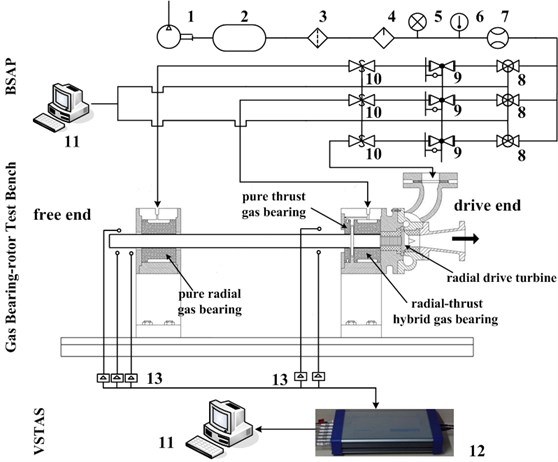
Fig. 1 shows a schematic view of the gas bearing-rotor system test rig, the supply air system into the bearings, as well as the vibration signal testing and analysis system. The test rig has a single-stage radial-turbine coaxial with a rotor driven by high-pressure air and a maximum speed of 120 krpm. A screw-type air compressor provides high-pressure air with maximum pressure of 1.2 MPa and maximum mass flow of 3.90 kg/s. The airflow into the bearings is controlled by regulating valves and by employing an adjustable air pressure regulator connected to the supply air lines. A K-type thermocouple monitors the temperature of the bearing supply gas. A calibrated mass-flow meter measures the mass flow rate into each bearing with an uncertainty of 0.195 kg/s. The regulation valve controls the air pressure in proportion to the rotational speed of the test rotor in the acceleration process.
Two pairs of eddy current sensors, which are near the test bearings, orthogonally positioned, and facing the rotor ends (the drive and free ends in Fig. 1), are utilized to measure the rotor lateral vibration amplitudes along the -vertical and -horizontal planes. Another eddy current sensor mounted at the free end of the rotor is used to act as a keyphasor signal for data acquisition and processing. The measuring range of the sensors is 1 mm. The linearity is 10.4 V/mm, and the range of measuring frequency is from 0 Hz to 10 kHz.
The rotor displacement voltage signals from the eddy current sensors are routed through a signal conditioner to bias their DC offset levels. The conditioned signals are input into the data acquisition and processing systems. The online data collection software can display the unfiltered real-time rotor orbits for the left and right sides of the rotor and can show the signal spectrums for each data channel by the fast Fourier transform. Reference [12] elucidated the test rig components. The test bench body comprises the test rotor, which is horizontally supported on two radial gas bearings. The test bench body also includes the test bearings and housings with air intake and discharge ports. The test rotor consists of an alloy structural steel with a 50 mm diameter and a 700 mm length and integrates a radial-driven turbine.
Fig. 1Layout of the gas bearing-rotor test rig and air supply system: 1. Air compressor; 2. Gas tank; 3. Filter; 4. Dryer; 5. Pressure gauge; 6. Thermometer; 7. Flow meter; 8. Pressure stabilizing valve; 9. Electro-pneumatic air regulator; 10. Safety shut-off valves; 11. Computer; 12. Data acquisition instrument; 13. Eddy current displace sensor
2.1. Test bearings
Fig. 2 details the dimensions of the test hydrostatic-dynamic hybrid gas bearing made of graphite alloy in the experiments. Three bearings are used on the test bench; one is a pure radial gas bearing at the free end of the rotor, another is a pure thrust bearing at the drive end, and another is a radial-thrust hybrid bearing at the drive end. The radial bearing has 2 lines equably located in the axial direction and 30 throttle holes equably located in the circumferential direction for each circle. Aside from these holes, herringbone grooves are placed in the internal surface of the journal bearing to increase the bearing dynamic load capacity. Therefore, the hydrostatic lubrication effect comes from the static pressure when the external pressured gas passes through the throttle holes. The bearing supply air pressure (BSAP) can be proactively controlled. Simultaneous hydrodynamic lubrication effect is provided by the gas wedges generated in the herringbone grooves. Table 1 lists the main parameters of the test rotor and bearings. Pressurized air flows through the orifices into each bearing.
Fig. 2Sketch of the hybrid gas-bearing structure
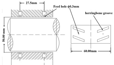
Table 1Main parameters of the test rig and gas bearings
Geometric parameters | Values |
Length, mm | 60 |
Inner diameter, mm | 50 |
Radial mean clearance, mm | 0.04 |
Clearance ratio, l | 0.0016 |
Spindle diameter, mm | 50 |
Rotor length, mm | 698 |
Thrust disk diameter, mm | 90 |
Bearing span, mm | 525 |
Rotor mass, kg | 10.36 |
3. Experimental procedure
Table 2 lists the nine test operating conditions based on various pressure supply control methods for modal experimental analysis and speed-up experiments. Operating conditions #1 to #4 represent the modal experiments, with BSAP ranging from 0.3 MPa to 0.6 MPa. Pressure gauges monitor the supply pressure into each test bearing.
Table 2Summary of rotor speed and feed pressure conditions
Operating condition # | Control strategy | |||||
BSAP | Speed when BSAP changes | Foundation features | ||||
Free end | Drive end | Free end | Drive end | |||
Modal experiments | 1 | 0.3 MPa | 0.3 MPa | The test rotor remains still | Without elastic rubber pad | |
2 | 0.4 MPa | 0.4 MPa | ||||
3 | 0.5 MPa | 0.5 MPa | ||||
4 | 0.6 MPa | 0.6 MPa | ||||
Speed-up experiments | 5 | 0.3 MPa | 0.3 MPa | BSAP remains unchanged during the run-up process | Without elastic rubber pad | |
6 | 0.3 MPa | 0.3 MPa | 0 r/min | |||
0.45 MPa | 0.3 MPa | 18000 r/min | ||||
7 | 0.3 MPa | 0.3 MPa | 0 r/min | Without elastic rubber pad | ||
0.45 MPa | 0.3 MPa | 18000 r/min | ||||
0.55 MPa | 0.3 MPa | 25000 r/min | ||||
8 | 0.3 MPa | 0.3 MPa | 0 r/min | Without elastic rubber pad | ||
0.45 MPa | 0.3 MPa | 18000 r/min | ||||
0.55 MPa | 0.3 MPa | 25000 r/min | ||||
0.55 MPa | 0.6 MPa | 27000 r/min | ||||
9 | 0.3 MPa | 0.3 MPa | 0 r/min | With elastic rubber pad | With elastic rubber pad | |
0.45 MPa | 0.3 MPa | 18000 r/min | ||||
0.55 MPa | 0.3 MPa | 25000 r/min | ||||
0.55 MPa | 0.6 MPa | 27000 r/min | ||||
Operating condition #5 is an accelerated rotor speed demonstration without any pressure control. Nevertheless, this condition has constant supply pressure over the entire acceleration range. The supply pressure governed by rotor speed is established for operating conditions #6 to #9 by using the electro-pneumatic air regulator. When the commands for changing bearing supply pressures are given, the electro-pneumatic air regulator automatically adjusts the supply pressure, with approximately 0.4 s to 0.5 s time delay. Operating conditions #1 to #8 are conducted without elastic rubbers at the free and drive ends. The BSAP of operating condition #9 are the same as that of operating condition #8. However, elastic rubbers are used in the condition.
Based on experimental results of measured rotor dynamic response in the Section 4.2, BSAP is changed step-by-step to postpone the occurrence of whip. In Table 2, the process of BSAP selection is given.
During operating conditions #6, the supply pressure remains at 0.3 MPa from 0 r/min to 18000 r/min, when 18000 r/min was reached, the supply pressure at the free end increased from 0.3 MPa to 0.45 MPa, and the drive end remained at 0.3 MPa.
All the BSAP plans in Table 2 are shown clearly and intuitively in Fig. 3. Figs. 3(a) to 3(d) show the BSAP plans for operating configurations #5 to #8, respectively. The inflection points in Fig. 3(a) to 3(d) display the changes for the bearing supply pressure at the given rotating speed.
For operating conditions #8 and #9, BSAP is controlled during the run-up process. When 27000 r/min was reached, the supply pressure increased from 0.3 MPa to 0.6 MPa at the drive end via an electro-pneumatic air regulator, and the free end changed as operating condition #7 (see Fig. 3(d)).
Fig. 3Bearing supply pressure for operating configurations #5 to #8
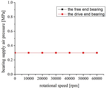
a) Bearing supply pressure for operating configuration #5
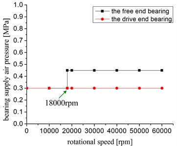
b) Bearing supply pressure for operating configuration #6
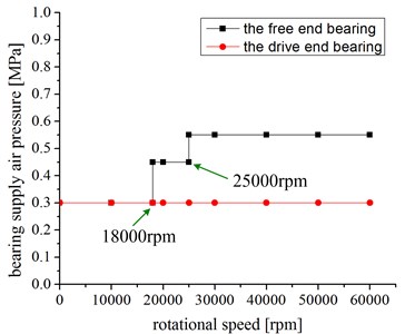
c) Bearing supply pressure for operating configuration #7
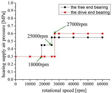
d) Bearing supply pressure for operating configuration #8
4. Experimental results
4.1. Modal experiments for different BSAP plans
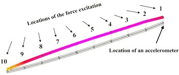
In the modal experiments, 10 points for the force excitation are arranged on the test rotor according to the rotor structure, and an accelerometer is fixed at point 1. The bearing at the free end lies between the point 8 and 9, and the bearing at the drive end is located between the point 2 and 3 (see Fig. 4(a)).
Transient excitation is generated by a hammer with a force sensor, and the response is measured by an accelerometer. To provide the needed frequency range, the quality and material of the hammer are selected by contrast to ensure its hardness. The modal shapes and frequencies of the gas bearing-rotor system under different bearing supply gas pressures are obtained by modal analysis.
The force and exponential decay windows added to the pulse and acceleration signals separately are used to weaken the effects of noise signals and truncation errors on the experimental results during data analysis. The complex-mode signal degree-of-freedom fitting method is adopted to gain the frequency response function of each test point.
Cylindrical whirling, conical whirling, and first-order bending natural frequencies are in the operating frequency band of the gas bearing-rotor system. Typical vibrational modes are shown in Fig. 4. The natural frequencies changing with bearing supply pressures are shown in Table 3.
Fig. 4Typical vibrational modes
a) Cylindrical whirling
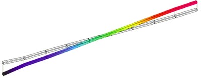
b) Conical whirling
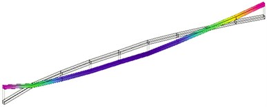
c) First-order bending
Table 3Experimental results for modal analysis
BSAP / MPa | Cylindrical whirling natural frequency / Hz | Conical whirling natural frequency / Hz | First-order bending natural frequency / Hz |
0.3 | 114.658 (6879 rpm) | 169.49 (10169 rpm) | 547.949 (32877 rpm) |
0.4 | 125.785 (7547 rpm) | 188.772 (11326 rpm) | 552.172 (33130 rpm) |
0.5 | 134.789 (8087 rpm) | 207.845 (12471 rpm) | 554.959 (33298 rpm) |
0.6 | 140.393 (8424 rpm) | 210.334 (12620 rpm) | 556.676 (33401 rpm) |
Cylindrical whirling, conical whirling, and first-order bending natural frequencies increase with increasing BSAP. Gas-film direct stiffness also increases with increasing BSAP. The natural frequencies for cylindrical whirling, conical whirling, and first-order bending at BSAP of 0.6 MPa respectively increased by 22.45 %, 24.10 %, and 1.59 %, compared with those at BSAP of 0.3 MPa.
Cylindrical and conical whirling natural frequencies reflect the gas-film supporting characteristics. The gas-film direct stiffness increased from 2.5×10⁶ N/m to 4.8×10⁶ N/m, and the relative change is significant. The first-order bending natural frequency reflects the inherent characteristics of the test rotor under restrained condition. The stiffness of the test rotor is about 108 N/m. Thus, the relative change for the gas film has minimal effect on the first-order bending natural frequency.
Table 3 presents each order natural frequency in all work speed ranges. The table is useful to determine the critical speed regions of the gas bearing-rotor system. The table also provides a basis for establishing a speeding-up control program and gives supporting data for analyzing low-frequency vibration, including whirling and whip in the speed-up process.
4.2. Measured rotor dynamic response for operating configurations #5 to #8
The sampling frequency of data acquisition instrument is set at 8 kHz during the experiments.
The background noise of data acquisition instrument is 0.03 mv, which is much smaller than the output signal of the sensors. In the experiments, the eddy current sensors are adopted. Environmental noise has been less affected eddy current fields of the sensors. Meanwhile the median filtering method is used to deal with vibration signal in order to reduce the effect of the noise.
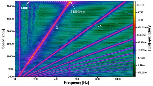
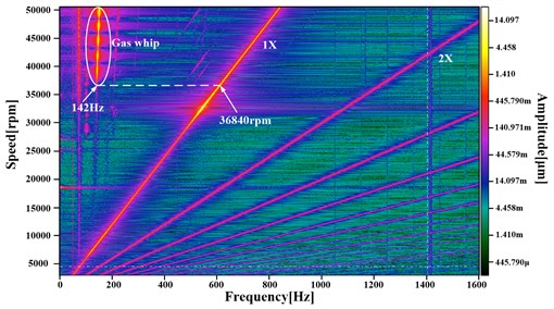
Figs. 5(a) to 5(d) depict the amplitudes of rotor synchronous and non-synchronous motion for each operating configuration. The luminosity of the color represents the amplitude size. The rotational speeds inserted in Figs. 5(a) to 5(d) show the working speeds when low frequencies occur. The synchronous components (1), higher-order harmonics (2), and lower-order harmonics (gas film whip) are marked in Fig. 5.
Gas film whip occurs at 18720 rpm for operating condition #5 as shown in Fig. 5(a). Gas film whip frequency maintains invariable basically. Similarly, the gas film whip appears at 25920 rpm, 31800 rpm, and 36840 rpm for operating condition #5, #6, and #7 separately.
Table 4 shows the critical speeds and frequency characteristics for operating configurations #5 to #8 on the basis of the test results depicted in Fig. 5. In operating configurations #5 to #8 (see Table 2), the rotor passes through the critical speed domains, including the cylindrical and conical whirling critical speeds, when the bearing supply pressures are at 0.3 MPa. Compared with the modal analysis results in Table 3, the critical speed results in the actual operations show that the cylindrical and conical whirling critical speeds give differences of 5.95 % to 8.69 % and −0.9 % to 6.00 % (the negative sign denotes that the mode values are greater than the results in the actual operations), respectively. The differences in the cylindrical whirling critical speeds are caused by the increased bearing gas-film dynamic pressure with rotational speed. The first-order bending critical speed under modal results is higher than that in the actual operations for operating configuration #8.
Gas film whip occurs in the run-up processes for operating configurations #5 to #8. The gas film whip frequency is locked in the cylindrical whirling critical speed, but is higher than the corresponding cylindrical whirling natural frequency in the modal results and actual operations. The difference is attributed to the increase of cylindrical whirling critical speed when the bearing gas film dynamic pressure increases with rotational speed.
Table 4 shows that when different bearing supply pressure plans are adopted, the corresponding power frequency speed for the beginning of gas film whip increases from 18720 rpm to 36840 rpm. The whirling ratio means the ratio of the low frequency to the power (operating) frequency, which represents the ratio of gas film whip frequency to the power frequency here. As you see in Table 4, the whirling ratios when gas film whip occurs decrease from operating condition #5 to operating condition #9. That’s because the power rotate speed for the occurrence of gas film whip increases from 18720 rpm to 36840 rpm.
Table 4Statistics of critical speeds and spectrum characteristics for operating configurations #5 to #9
Operating condition# | Critical speed for the free end at the horizontal direction | Low frequency (gas film whip) | Corresponding operating frequency when low frequency occurs | Whirling ratio when gas film whip occurs | ||
Cylindrical whirling | Conical whirling | First-order bending | ||||
5 | 7477 rpm | 10779 rpm | – | 128 Hz | 18720 rpm | 0.410 |
6 | 7295 rpm | 10057 rpm | – | 140 Hz | 25920 rpm | 0.324 |
7 | 7334 rpm | 10041 rpm | – | 140 Hz | 31800 rpm | 0.264 |
8 | 7289 rpm | 10077 rpm | 32687 rpm | 142 Hz | 36840 rpm | 0.231 |
9 | 5702 rpm | 7506 rpm | 31415 rpm | 142 Hz | 46962 rpm | 0.181 |
Fig. 53D waterfall plot diagram for rotor response versus shaft speed. Free-end bearing horizontal direction (FB). Operating conditions #5 to #8
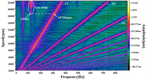
a) Operating condition #5
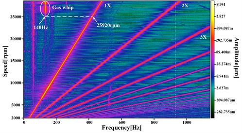
b) Operating condition #6
c) Operating condition #7
d) Operating condition #8
Fig. 6 displays the bifurcation diagrams and axis center tracks for conditions #5 and conditions #8. The bifurcation points are labeled in Fig. 6, which agrees with the information in Fig. 5. The axis center tracks are inserted in Fig. 6.
In the operating condition #5 in Fig. 6(a), the axis track is one-periodic motion at 8552 rpm and is chaotic motion at 20215 rpm after the bifurcation point. The boundary of chaos gradually increases with the rotational speed in Fig. 6(a). In the operating condition #8 in Fig. 6(b), the axis track is a chaotic motion at 44254 rpm after the bifurcation point, which differs from that of condition #5.
Fig. 6Bifurcation diagrams and axis center tracks for operating conditions #5 and #8
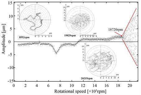
a) Operating configuration #5
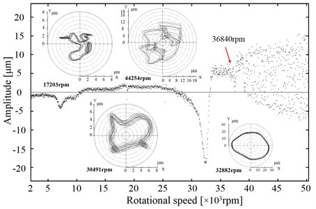
b) Operating configuration #8
4.3. Measured rotor dynamic response for operating configuration #9
To investigate the effect of elastic foundation on the rotor-bearing system stability, we adopted operating configuration #9 in Table 2. The bearing supply pressure plan of condition #9 is the same as that of condition #8. One silicone pad is fixed between the experimental platform and the bearing-seating platforms in condition #9.
Fig. 7 shows the 3D spectrum for the rotor response versus shaft speed during the run-up process under condition #9. Gas film half-speed whirling occurs at the first-order bending critical speed region, and the corresponding beginning power frequency speed is at 31500 rpm. Fig. 8(b) displays the axis center track and bifurcation diagram at the half-speed whirling region.
Gas film whip occurs when the power frequency speed is at 46962 rpm and the corresponding gas film whip frequency is at 142 Hz. The axis center track at 50888 rpm after the bifurcation point is the multi-period motion, as shown in Fig. 8(a).
The critical speeds of operating configuration #9 are lower than those of operating configuration #8. The operating rotational speed with gas film whip increased from 36840 rpm to 46962 rpm.
Fig. 73D spectrum for rotor response versus shaft speed. Free-end bearing horizontal direction (FB). Operating condition #9
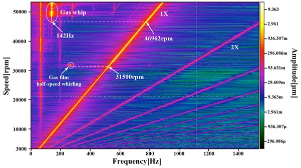
Fig. 8Bifurcation diagrams and axis center tracks for operating condition #9
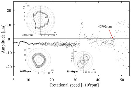
a) Bifurcation diagram during the run-up process for operating condition #9
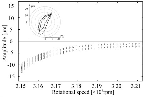
b) Bifurcation of partial enlargement from 31500 rpm to 32100 rpm
5. Conclusions
The bifurcation diagram based on experimental data is adopted to analyze the stability of gas bearing-rotor system in the paper. The paper provides several simple and effective measures including adjusting bearing supply air pressure and foundation characteristic to increase the stable rotational speed in the gas hybrid bearing-flexible rotor system. The main conclusions in the paper are described as follows.
Critical speeds under different bearing supply pressure plans are gained by modal experimental analysis, which provides the foundation of run-up controlling plans. The modal results provide support for confirming the locked frequency of gas film whip. The results show that the locking frequency of gas film whipping is at the lowest order natural frequency of shafting.
The paper presents the dynamic characteristics of gas film half-speed whirling and gas film whip by bifurcation diagrams and axis center tracks. Results show that multi-period and chaos motions appear after the bifurcation point. In addition, the shaft vibration amplitude increases with increasing rotational speed after gas film whip.
The adopted proper bearing supply pressure plan can increase the stability threshold speed of gas film whip from 18720 rpm to 36840 rpm. The dynamic and damping characteristics between the experimental platform and bearing-seating platform are changed to improve the stable rotational speed from 36840 rpm to 46962 rpm. Related experimental results can be used to improve the stability of the gas bearing-rotor system for high-speed power equipment.
The experiments also verify validity of nonlinear vibration analytical methods including bifurcation, spectral analysis and three-dimensional spectrum. The study provides ideas and application validation for software development for vibration characteristic analysis software of high speed rotating machinery.
References
-
Hamrock B. J. Fundamentals of Fluid Film Lubrication. New York. McGraw-Hill, 1994.
-
Castelli V., Elrod H. G. Solution of the stability problem for 360 degree self-acting, gas-lubricated bearing. Journal of Basic Engineering, Vol. 87, 1965, p. 199-212.
-
Jorgen W. L. The stability of an elastic rotor in journal bearings with flexible, damped supports. Journal of Applied Mechanics, Vol. 32, Issue 4, 1965, p. 911.
-
Ehrich F. F. Sub-harmonic vibration of rotors in bearing clearance. ASME Paper, No. 66-MD-1, 1966.
-
Ehrich F. F. Some observations of chaotic vibration phenomena in high speed rotor dynamics. Journal of Vibration and Acoustics, Vol. 113, 1991, p. 51-60.
-
Morosi S., Santos I. F. On the modeling of hybrid aerostatic-gas journal bearings. Proceedings of the Institution of Mechanical Engineers, Part J, Journal of Engineering Tribology, Vol. 225, 2011, p. 641-653.
-
Morosi S., Santos I. F. Active lubrication applied to radial gas journal bearings. Part 1: Modeling. Tribology International, Vol. 44, 2011, p. 1949-1958.
-
Morosi S., Santos I. F. Experimental Investigations of Active Air Bearings. ASME Turbo Expo, Copenhagen, Denmark, 2012.
-
San Andrés, L. Ryu K. Hybrid gas bearings with controlled supply pressure to eliminate rotor vibrations while crossing system critical speeds. Journal of Engineering for Gas Turbines and Power, Vol. 130, 2008, p. 062505-1-062505-10.
-
Yang J., Yang K., Chen C., et al. A criterion for evaluation stability of journal bearings-rotor system. Proceedings of GT2008, ASME Turbo Expo: Power for Land, Sea and Air, Berlin, Germany, 2008.
-
Chen C., Yang J., Lou J., et al. Experimental study on nonlinear dynamics characteristics of high-speed rotor-gas lubrication bearing system. Proceedings of GT2008, ASME Turbo Expo: Power for Land, Sea and Air, Berlin, Germany, 2008.
-
Han D., Yang J., Zhao C. et al. An experimental study on vibration characteristics for gas bearing-rotor system. Journal of Vibration Engineering, Vol. 25, Issue 6, 2012, p. 680-685, (in Chinese).
About this article
The work is supported by National Science and Technology projects (Grant No. 2012BAA11B02), and the support is gratefully acknowledged.
