Abstract
A belt driving system (BDS) of beam pumping unit is of the following characteristics: 1) energy can flow bidirectional freely; 2) the equivalent rotational inertia is a function of the pulley angle and the stiffness is a function of time. Take account of the above characteristics, a new mathematical model of nonlinear longitudinal vibration is built for BDS. The nonlinear relationship between the equivalent rotational inertia and driven-pulley angle as well as the equivalent stiffness and slipping angle is obtained. Comparing experiment results with simulated results, good agreement is found, which shows the simulation model is feasible. The amplitude-frequency curves are given, which show the jumping phenomenon. In addition, the amplitude-frequency curves are very sensitive to the system parameters, such as Young’s modulus, the preload force, the rotational inertia and load torque. In the details, with increasing Young’s modulus as well as decreasing the preload force, the jumping phenomenon moves the high frequency region, and the amplitude-frequency curves of the system move their mutational direction with load torque increasing. The jumping phenomenon of equivalent stiffness suggests that the jumping phenomenon of steady-state response of the pulley is influenced by the nonlinear dynamic stiffness of the belt. Real application indicates that the system energy consumption is increasing with the preload force decreasing, and it is also increasing with the load torque increasing. Therefore, the simulation analysis of nonlinear longitudinal vibration of BDS plays an important role in understanding the effects of the system parameters on the nonlinear steady-state response and saving energy by parameter optimization in practical application.
1. Introduction
The beam pumping units have been widely used in international and domestic oil field. When the crude oil is produced, the tremendous energy will be consumed. Improving system efficiency and reducing energy consumption are always an important research for artificial lift, which has been widely considered by experts all over the world [1]. At present, when energy consumption of beam pumping system is analyzed, the energy consumption of BDS is considered as a constant, for example, it is usually set to 2 %-10 % [1, 2]. However, the load torque of a belt-driving system not only fluctuates greatly but changes instantaneously, which increases friction loss power and decreases belt transmission efficiency. As a result, there is rotating variation loss for driven-pulley and crank, influencing the instantaneous motion of movement parts and nodes’ force-power parameters. Therefore, the dynamic behavior of belt-driving unit needs to be considered while nodes’ energy consumption is analyzed, and the simulation model of nonlinear longitudinal vibration for BDS needs to be built.
The dynamic performances of BDS are systematic studied by the experts and scholars from China and abroad. A large numbers of simulation models have been presented, but there are some shortcomings. A review of the references [3-10] identifies three well-defined groups of studies. The response of the transversal vibration belt has been studied by the first group [4-6]. The longitudinal vibration simulation models of BDS are given by the second group [7, 8]. The third group deals with describing coupled longitudinal-transverse dynamics of the belt [9, 10]. In the models above, most of which are derived with classical creep theory [11] or the shear theory [12]. However, the three groups have a common defect that the influences of variable equivalent stiffness and rotational inertia on belt-driving system’s vibration are neglected while uniform mass belt and pulleys are only considered.
Many experiments show that the contact parameters between the pulley and V-ribbed belts influences on the longitudinal vibration of belt-driving system. Therefore, the contact models are built by a proper method, which is very important to find an effective approach for modeling and predicting the dynamic response of belt-driving system. To do this, a lot of researches have been carried out. Leamy and Sheng [13, 14] developed a general, dynamic finite-element model of BDS, including a detailed frictional contact. A more general planar model of the belt-drive was developed in Ref. [15]. The absolute nodal coordinate formulation was originally proposed by Shabana [16]. Recently, Boltežar and Čepon [17] presented a belt-drive model using the absolute nodal coordinate formulation with a detailed contact formulation between the pulley and the belt. The method for the experimental identification of the contact parameters between the pulley and V-ribbed belts was presented in Ref. [18]. However, these models are not appropriate for modeling the belt-drive dynamics over longer time scales as they are computationally inefficient. Considering the influences of the motor speed fluctuation and the load torque fluctuation on the contact parameters, the equivalent stiffness of the belt is a function of time and the equivalent rotational inertia is a function of the pulley angle. Therefore, the influences of contact parameters on longitudinal vibration of BDS are needed to consider, and a new nonlinear longitudinal vibration model needs to be presented to solve the vibration problem of nonlinear system.
In this paper, the formulas of the equivalent stiffness and the rotational inertia as well as the generalized torque are deduced, a new nonlinear longitudinal vibration model of the belt-driving system is proposed for beam pumping system in Section 2. In Section 3 the measurement experiment of BDS is built to verify the feasibility of the proposed dynamics simulation method, and the characteristic of nonlinear longitudinal vibration and steady-state response of BDS are analyzed. In Section 4, the practical application of the new model is given to analyze the affecting factors of system energy consumption and guide for saving energy in oilfield. In Section 5 the signification of dynamic simulation research on BDS and the conclusions are summarized.
2. Mechanical model and dynamic nonlinear differential equations of BDS
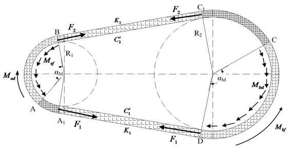
The physical figure of BDS is shown in Fig. 1 and the mechanical model of BDS is shown in Fig. 2. From Fig. 2, A1A is the static contact arc between belt and driving-pulley and AB the dynamic contact arc between belt and driving-pulley. Similarly, C1C is the static contact arc between belt and driven-pulley and CD the dynamic contact arc between belt and driven-pulley. The belt and pulley are running simultaneously in the static contact area. And there is relative sliding speed between belt and pulleys in the dynamic contact area, which is changed by the preload and load torque. The belt movement is disassembled into synchronous motion and relative motion. Therefore, the static contact area is considered as the reserve of the friction force, which could prevent skidding.
Fig. 1The physical figure of BDS
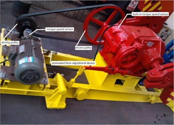
Fig. 2The mechanical model of BDS
For the mechanical model, the following assumptions are considered:
1) The belt is simplified as a massless spring.
2) The influence of slipping angle αM on the equivalent stiffness as well as the influence of the driven-pulley angle on the equivalent rotational inertia is considered.
3) The pulleys are considered to be rigid bodies.
Based on these assumptions, the BDS’s degrees of freedom are defined as , . Therefore, a new nonlinear longitudinal vibration model of BDS can be derived, as follows:
where is the equivalent rotational inertia of the driving pulley (kg·m2) and is the equivalent rotational inertia of the driven pulley (kg·m2), is the spring coefficient of the belt from point to point in Fig. 2 (N/m) and is the spring coefficient of the belt from point to point in Fig. 2 (N/m), and are radiuses of the pulleys, as shown in Fig. 2 (m), , are the generalized torques (N·m). is the equivalent damping of the belt from point to point in Fig. 2 and is the equivalent damping of the belt point to point in Fig. 2 (N·s /m2).
2.1. The equivalent rotational inertia
The energy balance equations for devices from the motor rotors to polished rod of pumping unit are deduced by the energy balance principle:
where, , and are the moment of inertia (kg·m2), the mass (kg) and the turn angle of the devices from the motor rotor to polished rod of pumping unit (rad).
2.2. The equivalent stiffness and damping
Currently, while the equivalent stiffness coefficients of tight and lose side , is calculated, the influence of pulley sliding angle on the elastic stiffness is ignored, as a result of which, the stiffness coefficients of tight and lose side may be considered to be constant and equivalent. However, considering the influence of the pulley instantaneous sliding angle on the equivalent stiffness, the equivalent stiffness is a variable. Therefore, the equivalent stiffness coefficients of belt are derived in this paper.
Based on the equivalent stiffness expression of the series springs, two balance equations are obtained:
where:
Combining Eqs. (3) and (4), the equivalent stiffness formulas are got, as follows:
And the equivalent damping formulas are calculated, as follows:
where, is the equivalent stiffness per unit length (N/m), is pitch line length of belt (m), is damping coefficient (s/m).
Because the Eq. (5) is transcendental equation, analytical solution cannot be obtained for the slipping angle. The Newton-Raphson method is applied to solve above transcendental equation, then the slipping angle at any moment, , is obtained.
2.3. The generalized torque
The infinitesimal element of BDS is removed to analyze the friction force between belt and pulley. The mechanical model of the infinitesimal element is built in Fig. 3.
Therefore, the equation is derived, as follows:
Considering the increment is small enough, the sine function of the increment is simplified:
Fig. 3The mechanical model of the infinitesimal element
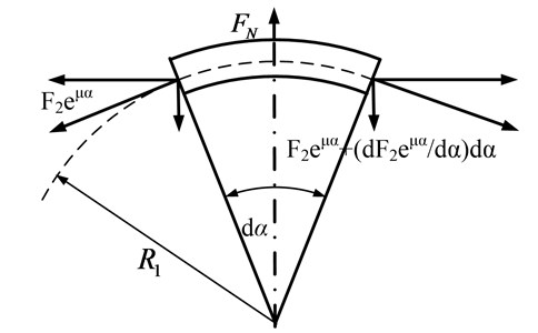
From Eqs. (7) and (8), the unit friction of driving pulley can be simplified as follows:
In the same way, the unit friction of driven pulley is given:
where:
where, is the initial tensile force of the belt (N).
Considering the sliding friction between belt and pulley, an equation is given, as follows:
The generalized torque is given, as follows:
where, is the equivalent driving torque of BDS (N·m), and is the load torque of BDS (N·m).
From Ref. [1], the expression of the driving torque and the load torque are given, as follows:
where, is the torque factor of pumping unit (m); is the counterbalance weight of pumping unit (N); is the maximum balanceable torque (N·m); is the lagging angle of balance weight (rad); is the drive ratio of gearbox; is the load of polished rod (N); is synchronous speed of motor (rad/s); is the rated power of motor (kW); is the rated speed of motor (min-1); is the synchronous speed of motor (min-1); is the overload coefficient of motor which is the ratio of maximum torque to rated torque; is motor critical slip; is motor rated slip; is load torque (N·m).
3. Experiment and discussion
3.1. The experimental facility of BDS
The experimental facility is shown in Fig. 1. The torque-speed sensor is installed on the output shaft of motor and input shaft of gearbox. When the system is a stable state, the data is obtained by torque-speed sensor.
1) The preload force.
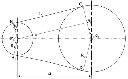
The preload force is one of the important characteristic parameters, which influences on the dynamic behaviors of BDS [8]. Therefore, the preload force is given accurately in this work. The geometrical model of BDS is shown in Fig. 4.
From Fig. 4, the relational formula is obtained as follows:
where, is the adjusted base length of the belt (m).
With the geometric relationships, the arc length formulas of the driving-pulley and driven-pulley as well as tangent length of the belt are derived:
Combining Eqs. (16) and (17), the preloaded force of the belt is derived:
where, is Young’s modulus (Pa), is the cross-section area of the belt (m2).
Fig. 4The geometrical model of BDS
2) The polished rod load.
In order to verify the feasibility of the simulation method, the experimental facility of the surface driving system for beam pumping system is designed (see Fig. 5). From Fig. 5, the sucker rod is replaced by many different masses, and the load of the polished rod is changed by altering different masses. The load of polished rod is given, as follows:
where, is the gravity of the masses (N); is the quantity of the masses; is the gravitational acceleration (m/s2) and is the acceleration of the polished rod (m/s2).
3) The percentage of energy consumption.
With the simulation results of the new nonlinear longitudinal vibration model, the equation for percentage of energy consumption is derived, as follows:
where, is the percentage of instantaneous energy consumption (%); is the percentage of average energy consumption (%); is the power of sliding friction (kw); is the effective tension (N); is the symbolic function, it is defined as shown below:
3.2. Results and discussion
3.2.1. Precision verification
The fundamental parameters of system dynamic simulation are given in Table 1. Applying the fourth order Runge-Kutta method, the dynamic simulating analysis of nonlinear longitudinal vibration model for BDS is carried out with zero initial conditions. And, Fig. 6 shows the measured result of driven-pulley torque. Considering the measured torque as a systematic excitation, the responses of BDS are given in Fig. 7.
Fig. 5The structure diagram of beam pumping unit
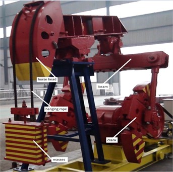
Fig. 7 shows that the simulation precision is less than plus or minus 10 percent, and the simulated speeds of pulleys have found a good match with the experimental ones. Therefore, the simulation results are enough to content application. Meanwhile, as in conjunction with Fig. 6, when the pulley torque appears negative values, the angular velocity of driving-pulley installed on the motor output-shaft exceeds the synchronous speed of motor rotor. At this point, the motor is dragged and the energy appears reverse flow, which needs to be considered in the analyzing of energy consumption.
Fig. 6The driven-pulley torque with the crank angle
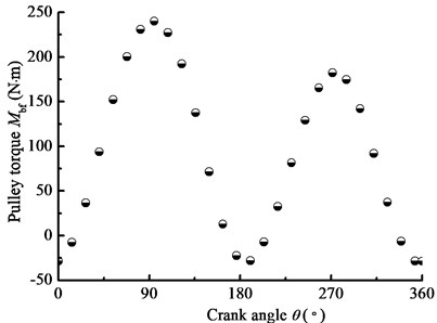
Fig. 7The pulley velocity with crank angle
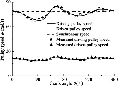
Table 1The fundamental parameters of BDS
Item | Unit | Value | Item | Unit | Value |
kW | 10 | r/min | 750 | ||
r/min | 667 | m | 3.55 | ||
kg/m | 0.37 | m2 | 1.55×10⁻⁴ | ||
m | 0.172 | m | 0.635 | ||
Pa | 2×10⁹ | 2.5 | |||
0.6 | 3 | ||||
0.95 | 35 |
3.2.2. Parametric regularity
Taking beam pumping unit as the research object, the driven-pulley torque is used as the excitation in Fig. 6, Fig. 8 shows the changing laws of the main parameters. In the details, Fig. 8(a) shows the equivalent rotational inertia for driven-pulley with the crank angle and Fig. 8(b) shows the derivative of the rotational inertia for driven-pulley with the crank angle. Fig. 8(c) and Fig. 8(d) show the slipping angle and equivalent stiffness of the belt with the crank. As you can see in the above figures, the changing law of the equivalent rotational inertia is a sine function, whose amplitude and frequency are different with the different load devices. The equivalent stiffness of the belt is affected by the slipping angle, decreasing with the slipping angle increasing. Based on the theory of nonlinearity, the instantaneous variable equivalent rotational inertia as well as equivalent stiffness has influence on the vibration system. Therefore, the research on the changing law of the equivalent stiffness as well as the equivalent rotational inertia is the foundation of nonlinear characteristic analysis.
Fig. 8The changing laws of the main parameters of nonlinear system in time domain
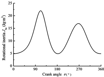
a) Equivalent rotational inertia
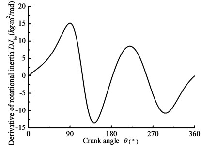
b) Derivative of the rotational inertia
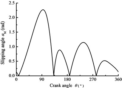
c) Slipping angle
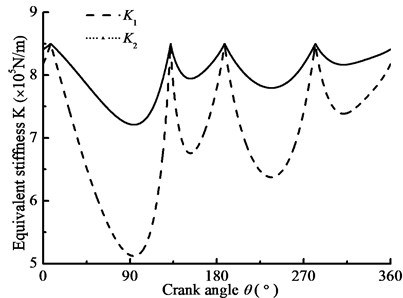
d) Equivalent stiffness
3.2.3. Nonlinear characteristic analysis
When BDS is applied to a high-speed driving machine, the load torque of the system can be defined as follow:
When –1000 N·m, 1000 N·m, 4200 N·m, 2000 N, 2×10⁹ N·m, 1 rad/s, the steady-state response of nonlinear longitudinal vibration is given by changing load frequency. Changing Young’s modulus , Fig. 9(a) and (b) show the comparison of the response of the belt pulleys angle with different belt materials. In addition, changing the parameter , Fig. 10(a) and (b) show the comparison of the amplitude-frequency response curves with different driven-pulley torques. Furthermore, changing preload force , Fig. 11(a) and (b) show the comparison of the response of the pulleys angle with different preload forces. In the details, BDS shows the jumping phenomenon, which is a consequence of the nonlinear dynamic tension of the belt. In Fig. 9(a) and (b), the jumping phenomena of the different materials system occurs in different scopes and the jumping phenomenon of BDS with the smaller Young’s modulus occurs in lower excitation frequency range. In addition, when the Young’s modulus is increasing, the jumping phenomenon will be more obvious. In the other word, the nonlinear vibration characteristic of BDS is more pronounced with the Young’s modulus decreasing. In Fig. 10(a) and (b), the jumping phenomenon in the resonance of the BDS with different driven-pulley torque occurs at the same conditions. So, with increasing load torque, the nonlinear longitudinal vibration characteristic is more obvious, but it will not change frequency range of occurrence of the jumping phenomenon. In Fig. 11(a) and (b), with decreasing preload force, the jumping phenomenon moves to the higher excitation frequency area. Conversely, the jumping phenomenon will occur in the lower frequency when the preload force is increasing.
Fig. 9The pulley angle amplitude-frequency curves for the different belt materials
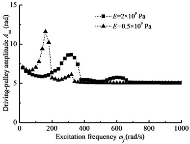
a) Driving-pulley amplitude-frequency curve
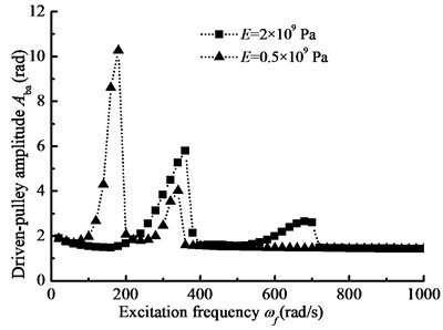
b) Driven-pulley amplitude-frequency curve
Fig. 10The pulley angle amplitude-frequency curves for the different driven-pulley torques
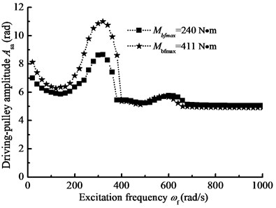
a) Driving-pulley amplitude-frequency curve
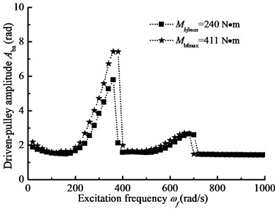
b) Driven-pulley amplitude-frequency curve
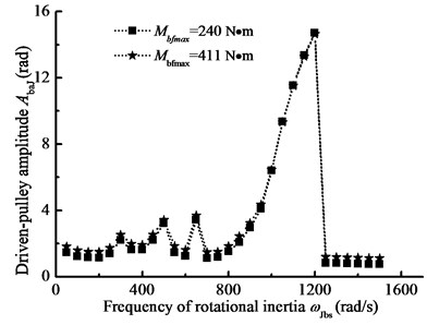
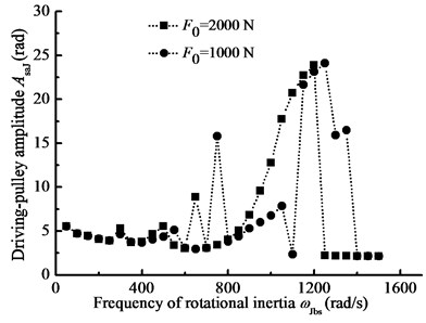
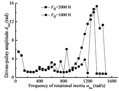
When –1000 N·m, 1000 N·m, 4200 N·m, 2000 N, 2×10⁹ N·m, 10 rad/s, the characteristic of nonlinear longitudinal vibration is analyzed by changing the period of the rotational inertia. Changing Young’s modulus Fig. 12 gives the pulley amplitude-frequency curves for different belt materials. Comparing Fig. 9, the pulley angle amplitude and frequency area of occurrence of jumping phenomenon is different, but they all show clear hysteresis phenomenon. In addition, changing the parameter , Fig. 13(a) and (b) show the comparison of the response of the pulleys with different driven-pulley torques. From Fig. 13, with increasing load torque, the amplitude-frequency curve of the system will move their mutational direction. Compared to Fig. 11, the changing of rotational inertia frequency has more influence on nonlinear longitudinal vibration. Furthermore, changing the preload force, Fig. 14 gives amplitude-frequency curves for different preload forces. In Fig. 14, when the preload force is decreasing, the jumping phenomenon of nonlinear vibration will occur in high frequency region. In conclusion, the rotational inertia is a major parameter, influencing on the nonlinear vibration characteristic of BDS.
Fig. 11The pulley angle amplitude-frequency curves for the different preload forces
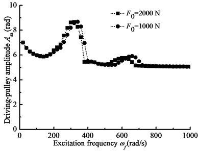
a) Driving-pulley amplitude-frequency curve
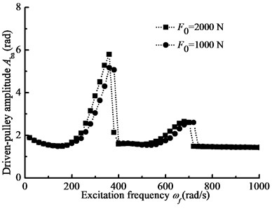
b) Driven-pulley amplitude-frequency curve
Fig. 12The pulley angle amplitude-frequency curves for the different belt materials
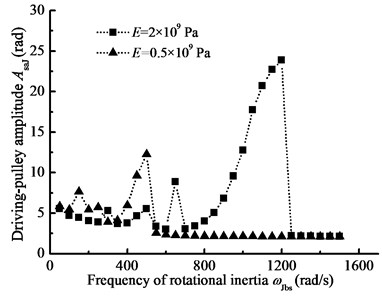
a) Driving-pulley amplitude-frequency curve
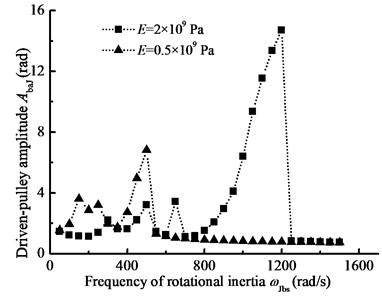
b) Driven-pulley amplitude-frequency curve
3.2.4. Sensitive parameters of equivalent stiffness
In this section, when –1000 N·m, 1000 N·m, 4200 N·m, 2000 N, 2×10⁹ N·m, 1 rad/s, 10 rad/s, the steady state response of BDS is simulated by changing one of them and the influences of parameters on the belt equivalent stiffness are examined.
Fig. 13The pulley angle amplitude-frequency curves for the different driven-pulley torques
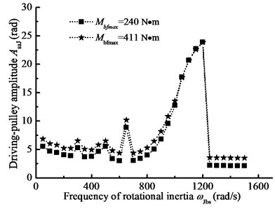
a) Driving-pulley amplitude-frequency curve
b) Driven-pulley amplitude-frequency curve
Fig. 14The pulley angle amplitude-frequency curves for the different preload forces
a) Driving-pulley amplitude-frequency curve
b) Driven-pulley amplitude-frequency curve
Fig. 15Equivalent stiffness amplitude-frequency curve
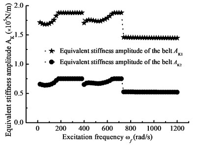
a) Frequency of load torque
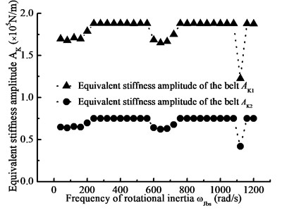
b) Frequency of rotational inertia
Changing the frequency of load torque and rotational inertia, Fig. 15 shows the equivalent stiffness amplitude-frequency curve. And changing the preload force and driven-pulley torque, Fig. 16 shows the equivalent stiffness amplitude curve with the main parameters. In the details, the frequencies of load torque and rotational inertia will all affect equivalent stiffness and thus affect nonlinear longitudinal vibration of BDS. According to contrast Fig. 15(a) and Fig. 15(b), the equivalent stiffness has larger fluctuation in the high frequency region of rotational inertia. In addition, the equivalent stiffness is influenced by the preload force and load torque. In Fig. 16, the equivalent stiffness amplitude has a reducing trend with the preload force increasing, and it has an increasing trend with the driven-pulley torque increasing. Therefore, the jumping phenomenon of the steady state response is influenced by the nonlinear stiffness of belt.
Fig. 16Equivalent stiffness amplitude curve with main parameter
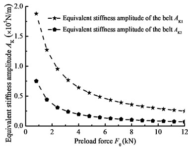
a) Preload force
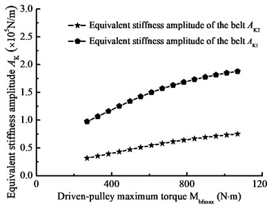
b) Driven-pulley maximum torque
3.2.5. Sensitive parameters of pulley angle
In this part, when 30 kw, –1000 N·m, 1000 N·m, 4200 N·m, 6000 N, 2×10⁹ N·m, 1 rad/s, 10 rad/s, the steady-state response of pulley angle is simulated by changing the parameter , and the influence of load torque on pulley angle amplitude is given in Fig. 17(a). And, when 10 kw, –4000 N·m, 4000 N·m, 7200 N·m, 6000 N, 2×10⁹ N·m, 1 rad/s, 10 rad/s, the steady-state response of pulley angle is simulated by changing the parameter , and the influence of load torque degree on pulley angle is given in Fig. 17(b). From Fig. 17, the pulley angle amplitude is increasing with the load torque increasing. In addition, when load torque is unbalance, the pulley angle will have larger fluctuation. Therefore, reducing load torque and keeping torque balance are beneficial to reduce nonlinear longitudinal vibration of BDS.
Fig. 17Pulley angle amplitude curve with sensitive parameter
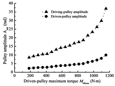
a) Driven-pulley maximum torque
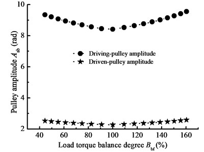
b) Load torque balance degree
4. Application
Based on the new longitudinal vibration model of BDS, the simulation software is developed for energy consumption analysis. By simulating analysis, the major factors of energy-consuming and the strategy of energy-conserving are presented.
4.1. The preload force
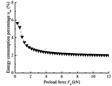
When –1000 N·m, 1000 N·m, 7200 N·m, 1 rad/s; 1 rad/s; the preload force is changed by adjusting the pulley center distance, and the energy consumption as a percentage of the total energy is calculated. Fig. 18 gives the energy consumption percentage under different preload forces.
Fig. 18 shows that, the energy consumption is influenced by the preload force. As the preload force decreases, the energy consumption will increase. Combing with Fig. 16(a), when the preload force becomes very small, there will be a major fluctuation in equivalent stiffness and a sliding failure between belt and pulleys, at this point, the BDS is no longer operating and all input energy of BDS is converted into friction consumption. At the other extreme, when the preload force becomes very big, the BDS has the low energy consumption but a short lifetime. Therefore, the dynamic simulation of BDS with the proposed new model is needed to determine the pulley center distance and proper preload force, which is important significance for energy-saving in oilfield.
Fig. 18Energy consumption percentage with the preload force
4.2. The maximum load torque
When –1000 N·m, 1000 N·m, 4200 N·m, 6000 N; 1 rad/s; 1 rad/s; the energy consumption percentage is obtained by changing the parameter . Fig. 19 shows the energy consumption percentage under different the driven-pulley torques.
Fig. 19Energy consumption percentage with the driven-pulley maximum torque
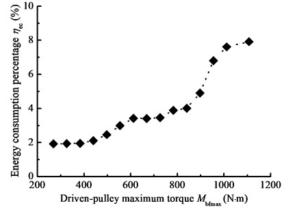
Fig. 19 shows that the driven-pulley torque influences on the energy consumption of BDS. The energy consumption is increasing with the driven-pulley torque increasing. Combing with Fig. 17, the greater load torque as well as torque unbalance increases nonlinear vibration of BDS and reduces the energy consumption. Therefore, based on the new model proposed in this paper, the dynamic simulation analysis of BDS is useful to understand the influence of sensitive parameters on system efficiency, optimize the sucker parameters and determine the reasonable driven-pulley torque.
5. Conclusions
The following conclusions can be summarized from the theoretical formulation and the numerical studies in this paper:
1) Considering the influence of the driven-pulley angle on the equivalent rotational inertia as well as the influence of pulley sliding angle on the equivalent stiffness, the equations of the equivalent rotational inertia and stiffness are derived. With the bidirectional flow of energy and the variation of the equivalent rotational inertia and stiffness, a new simulation model of nonlinear longitudinal vibration for BDS is built. In order to analyze major factors of energy consumption, an equation of the percentage of the energy consumption is obtained.
2) In order to verify the feasibility of the proposed dynamics simulation model, the measurement experiment of pulley speed is built. It shows that the simulation precision is less than plus or minus 10 percent, and the simulated and experimental speeds of pulleys have a good match.
3) There is a jumping phenomenon in the amplitude-frequency curve, which is a major characteristic of nonlinear vibration. The amplitude-frequency curves are very sensitive to the system parameters, such as Young’s modulus, the preload force, the rotational inertia and load torque. When the frequency of rotational inertia as well as frequency of load torque is slowly increased, there will be more obvious jumping phenomenon under same conditions. In the details, with increasing Young’s modulus as well as decreasing the preload force, the jumping phenomenon moves the high frequency region, and the amplitude-frequency curves of the system move their mutational direction with load torque increasing. In addition, the equivalent stiffness amplitude is jumping with the frequency of load torque slowly increasing as well as frequency of rotational inertia increasing, and it is also sensitive to the main parameters, such as the frequency of rotational inertia, the frequency of load torque, preload force and load torque. With decreasing preload force as well as increasing load torque, the equivalent stiffness amplitude is increasing. Therefore, the jumping phenomenon of equivalent stiffness suggests that the jumping phenomenon of steady-state response of the pulley is influenced by the nonlinear dynamic stiffness of the belt. Furthermore, with reducing load torque and keeping torque balance, the pulley angle amplitude is reducing. In a practical application, the energy consumption is increasing with the load torque increasing, and it is also increasing with the preload force decreasing. Therefore, the simulation analysis of nonlinear longitudinal vibration of BDS plays an important role in understanding the effects of the system parameters on the nonlinear steady-state response and saving energy by parameter optimization in practical application.
References
-
Sh. M. Dong Couputer simulation of dynamic parameters of rod pumping system and system optimization. Petroleum Industry Press, Beijing, China, 2003, (in Chinese).
-
Čepon G., Boltežar M. Dynamics of a belt-drive system using a linear complementarity problem for the belt-pulley contact description. Journal of Sound and Vibration, Vol. 319, Issues 3-5, 2009, p. 1019-1035.
-
Abrate S. Vibrations of belts and belt drives. Mechanism and Machine Theory, Vol. 27, Issue 6, 1992, p. 645-659.
-
Andrianov I. V., Van Horssen W. T. On the transversal vibrations of a conveyor belt: applicability of simplified models. Journal of Sound and Vibration, Vol. 313, Issues 3-5, 2008, p. 822-829.
-
Suweken G., Van Horssen W. T. On the transversal vibrations of a conveyor belt with a low and time-varying velocity part II: the beam-like case. Journal of Sound and Vibration, Vol. 267, Issue 5, 2003, p. 1007-1027.
-
Čepon G., Boltežar M. Computing the dynamic response of an axially moving continuum. Journal of Sound and Vibration, Vol. 300, Issues 1-2, 2007, p. 316-329.
-
Hu Ding, Jean W. Zu Effect of one-way clutch on the nonlinear vibration of belt-drive systems with a continuous belt model. Journal of Sound and Vibration, Vol. 332, Issue 24, 2013, p. 6472-6487.
-
Lee T. F., Huang A. Ch. Vibration suppression in belt-driven servo systems containing uncertain nonlinear dynamics. Journal of Sound and Vibration, Vol. 330, Issue 1, 2011, p. 17-26.
-
Beikmann R. S., Perkins N. C., Ulsoy A. G. Nonlinear coupled vibration response of serpentine belt drive systems. Journal of Vibration and Acoustics, Vol. 118, Issue 4, 1996, p. 567-573.
-
Scurtu P. R., Clark M., Zu J. W. Coupled longitudinal and transverse vibration of automotive belts under longitudinal excitations using analog equation method. Journal of Vibration and Control, Vol. 18, Issue 9, 2011, p. 1336-1352.
-
Bechtel S. E., Vohra S., Jacob K. I., Carlson C. D. Stretching and slipping of belts and fibers on pulleys. Journal of Applied Mechanics, Vol. 67, Issue 1, 2000, p. 197-206.
-
Gerbert G. Belt slip-a unified approach. Journal of Mechanical Design, Vol. 118, Issue 3, 1996, p. 432-438.
-
Leamy M. J., Wasfy T. M. Transient and steady-state dynamic finite element modeling of belt-drives. Journal of Dynamic Systems, Vol. 124, Issue 4, 2002, p. 575-581.
-
Sheng G., Lee J. H., Narravula V., Song D. Experimental characterization and analysis of wet belt friction and the vibro-acoustic behavior. Tribology International, Vol. 44, Issue 3, 2011, p. 258-265.
-
Kerkkänen K. S., Daniel G. V., Mikkola A. M. Modeling of belt-drives using a large deformation finite element formulation. Nonlinear Dynamics, Vol. 43, Issue 3, 2006, p. 239-256.
-
Shabana A. A. Dynamics of multibody systemsthird edition. Cambridge University Press, 2005.
-
Čepon G., Manin L., Boltežar M. Introduction of damping into the flexible multibody belt-drive model: A numerical and experimental investigation. Journal of Sound and Vibration, Vol. 324, Issues 1-2, 2009, p. 283-296.
-
Čepon G., Manin L., Boltežar M. Experimental identification of the contact parameters between a V-ribbed belt and a pulley. Mechanism and Machine Theory, Vol. 45, Issue 10, 2010, p. 1424-1433.
About this article
This project is supported by National Natural Science Foundation of China (No. 50974108) and National Natural Science Foundation of China (No. 51174175).
