Abstract
The main characteristic of a motor built-in high speed spindle with ATC is to perform high-speed cutting. The drawbar mechanism of spindle provides the clamping force to grip the toolholder for machining. Poor connection between the shaft-taper hole and toolholder will cause the danger of toolholder to loose and slip. In this study, a solid modeling method is adopted to investigate the effects of clamping force provided by the drawbar mechanism. Contact analyses of the toolholder and shaft-taper hole using contact elements are conducted. The stresses distribution between the toolholder and shaft-taper hole is then obtained. The effects of pre-stress are then adopted for subsequent finite element modal analysis. The finite element modal analysis results are verified by the experimental modal testing. The results presented herein indicate that it is effective in simulating and analyzing the contact relationship between the toolholder and shaft-taper hole by using contact elements. Also, it is proved that the shaft-toolholder system can provide different friction torque to resist the cutting force due to different clamping forces and coefficients of friction.
1. Introduction
As the science and technology progresses, the manufacture by using CNC milling machine is a very well-known technology. The spindle is a major unit of a CNC milling machine. The spindle has to provide the required stiffness to resist the cutting force. The connection status between the shaft and toolholder will be having great impact in the machining efficiency and accurate. Therefore, it is important to establish a rational finite element model for the static and dynamic analyses of the spindle. Hughes etc. [1] proposed a finite element method (FEM) for a class of contact-impact problems. Several sample problems were presented which demonstrate the accuracy and versatility of the analysis algorithm. Oysu [2] proposed a test example in a separate analysis using the FEM or using the Lagrange multiplier approach combined with finite element analysis (FEA). The results obtained from both methods are similar. However, the latter analysis speed is faster than the former. Gonza’lez [3] presented a unified formulation for the combination of the FEM and the boundary element method (BEM) in 3D frictional contact problems that is based on the use of localized Lagrange multipliers (LLMs). In this work a displacement contact frame is inserted between the FE and BE interface meshes, discretized and finally connected to the contacting substructures using LLMs collocated at the mesh-interface nodes. This methodology provided a partitioned formulation which preserves software modularity and facilitates the connection of non-matching FE and BE meshes. Ju etc. [4] developed a new contact element based on the penalty function method for frictional contact problems in FEA. The novel advantage of this new algorithm is that the contact element stiffness matrix is symmetric, even for frictional contact problems with a large sliding mode. The results using this new element are virtually identical to those obtained using conventional unsymmetrical contact element stiffness matrices. However, FEA using this new contact element requires only half the computing time and half the storage space of those using unsymmetrical contact elements. Ezawa etc. [5] designed to improve the accuracy of analysis using the hybrid method combining the FEM and the BEM. Furthermore, the penalty function is applied to introduce the contact conditions. By considering the application to general slide movements, a new eight-node contact element has been developed. Results confirm the validity and the accuracy of this method. The penalty function method is suitable for large distorted elements, friction, and augmented Lagrangian algorithm.
On the other hand, regenerative chatter is a well-known machining problem that results in unstable cutting process, poor surface quality and reduced material removal rate. This undesired self-excited vibration problem is one of the main obstacles in utilizing the total capacity of a machine tool in production. In order to obtain a chatter-free process on a machining center, stability diagrams were used by Ertürk etc. [6]. Their study presents an analytical method that uses Timoshenko beam theory for calculating the tool point FRF of a given combination by using the receptance coupling and structural modification methods to develop a reliable mathematical model to predict tool point FRF in a machining center and to make use of this model in studying the effects of individual bearing and contact parameters on tool point FRF. The model is also used to study the effects of several spindle, holder and tool parameters on chatter stability, and is verified by comparing the natural frequencies of a spindle-holder-tool assembly obtained from the model with those obtained from finite element software. Ertürk etc. [7] studied the effects of spindle-holder and holder-tool interface dynamics, as well as the effects of individual bearings on the tool point FRF by using their recently developed analytical model for predicting the tool point FRF of spindle-holder-tool assemblies. Some conclusions are made in this paper that bearing dynamics control the rigid body modes of the assembly, whereas, spindle-holder interface dynamics mainly affects the first elastic mode, while holder-tool interface dynamics alters the second elastic mode. Individual bearing and interface translational stiffness and damping values control the natural frequency and the peak of their relevant modes, respectively. Based on the effect analysis carried out, a systematic approach is suggested for identifying bearing and interface contact parameters from experimental measurements. In the contact studies for the high speed spindle, the major objects are mostly concentrated in dynamic analysis of spindle and functional design [8-16]. Only few studies focus on the contact behavior between the shaft-taper hole and the toolholder. Namazi etc. [17] proposed a majority of the chatter vibrations in high-speed milling originate due to flexible connections at the toolholder-spindle, and tool-toolholder interfaces. The holder-spindle taper contact is modeled by uniformly distributed translational and rotational springs. The springs are identified by minimizing the error between the experimentally measured and estimated frequency response of the spindle assembly. The paper also presents identification of the spindle’s dynamic response with a holder interface, and its receptance coupling with the holder-tool stick out which is modeled by Timoshenko beam elements. The proposed methods allow prediction of frequency response functions at the tool tip by receptance coupling of tools and holders to the spindle, as well as analyzing the influence of relative wear at the contact by removing discrete contact springs between the holder and spindle. Sun etc. [18] proposed a dynamic analysis and static analysis method to design for the dimension of high speed spindle system HSK-Clamping-Unit/Form 63F. The tooling steel was utilized to model the drawbar shaft, clamping cone, gripper, and hollow-shaft-taper parts. The finite element analysis software, “ANSYS”, was used to design the clamping system for getting better clamping force by change the structure of the clamping system. Hwang etc. [19] concentrated on the type synthesis of the tool-holding device, and the analysis of the mechanical advantage for the tool-holding device, and the development of a new draw-bar system. The design techniques to develop a complete new draw-bar are illustrates. Chen etc. [20, 21] proposed a key factor in designing a motor-built-in high speed spindle is to assemble the rotor-shaft by means of hot-fit. This paper presents a study of the influence of the hot-fit rotor on the local stiffness of the shaft. The dynamic analyses of the hot-fit rotor-shaft assembly using contact elements are conducted. The stresses distribution between the rotor and the shaft is then available thereafter. These studies also consist of theoretical contact analysis and an equivalent static analysis for the contact stress verifications of finite contact element analysis. The results obtained from this study indicate: it can be accurate and effective in analyzing the dynamic behavior of the rotary shaft system with hot-fit components by using contact elements.
The motor built-in high speed spindle is one of the key technologies for the precision manufacture. Make a comprehensive survey of the domestic and foreign researches, the spindle was studied by using the finite element analysis. But, there is no investigation on the corresponding relationship which is important for the machining efficiency and accuracy between the toolholder and shaft-taper hole. Therefore, it is a worthy study subject that how to accurate and effective analyze the relationship.
2. Approaches for the study
In this study, the shaft-toolholder assembly is modeled and analyzed by using ANSYS. In order to understand the friction torque provided by shaft and toolholder under contact, the modeling is constructed with contact element. ANSYS supports three contact models: node-to-node, node-to-surface, and surface-to-surface. Each type of model uses a different set of ANSYS contact elements. This study adopts 3D surface-to-surface model to study the dynamic characters of a shaft-toolholder assembly. The finite element model of the assembly is first constructed. The contact pairs are then identified by using target and contact elements. It is necessary to define stiffness for all contact problems. The amount of penetration between contact and target surfaces depends on the normal stiffness. Higher stiffness values can lead to convergence difficulties. In general, the contact stiffness should be large enough to ensure the smallest penetration and small enough to ensure convergence. ANSYS is capable of estimating the contact stiffness based on the material properties of the deformed elements. It employs FKN, a necessary normal contact stiffness factor which scales the contact stiffness as a fraction of the Young’s modulus of the underlying material, to control the contact behavior between the contact and target elements. The usual scaling range of FKN is 0.01~10.
In the analysis process, a stationary shaft-toolholder system is assumed and the contact element theory is used to analysis the normal force on the surface of shaft-taper hole. The normal force distribution on the cone surface is not uniform, since the normal force on the cone surface will change due to different cross-section area. The normal force is larger as the cross-section area is smaller. The normal force is inversely proportional to the cross-section area. After the normal force is calculated, the friction torque provided by the surface friction force can be obtained by multiply normal force of node at the cone surface with the friction coefficient and cross-section radius.
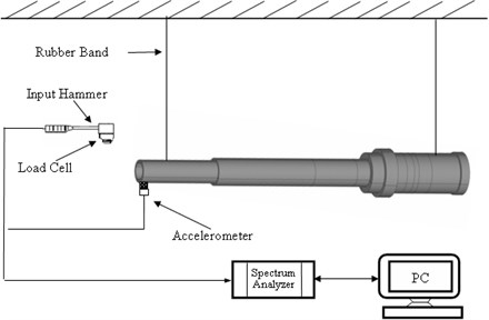
In this stage, in order to verify the accuracy of the constructed finite element model, the finite element modal analysis is performed to obtain the natural frequencies and is verified with those obtained from modal testing. Fig. 1 shows the diagram of experiment apparatus. Finally, the maximum speed of the studied commercial spindle is considered in the analysis for understanding the differences of results obtained from the stationary and dynamic analysis, respectively.
Fig. 1Schematic of the experiment apparatus
3. Illustrated actual example
In this study, the clamping force is firstly decided. And the friction coefficients of steel vs. steel are between 0.029-0.12 obtained by look-up table. The commercialized 4.6 Kw engraving spindle with ATC is studied in this paper. For the shaft-toolholder system, it is constructed by rotary shaft, drawbar mechanism and toolholder. The schemes of shaft and toolholder are shown in Fig. 2-3, respectively.
Fig. 2The design chart of shaft
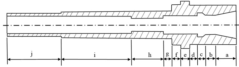
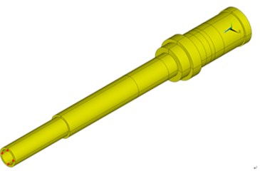
Fig. 3The design chart of toolholder
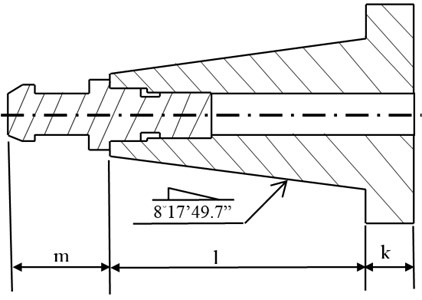
First, the 3-D solid modeling is constructed with element SOLID 185, and their detailed dimensions are shown in Table 1. The shaft and toolholder are modeling with four one-quarter circle and are manually meshed in a uniform pattern. The mesh of shaft is as follows: The length is 290 mm. The contact part with the toolholder is 26.057 mm, and is meshed into 40 divisions in longitudinal length. For the other part of shaft, each division is 1mm in the longitudinal, 11 divisions in circumferentially, and since radial direction thickness are different, as shown in Fig. 4, 8 divisions in Part A, 11 divisions in Part B, 15 divisions in Part C, 10 divisions in Part D, 4 divisions in Part E, 7 divisions in Part F, 5 divisions in Part G, and 6 divisions in Part H; The toolholder total length is 64.5 mm. The contact part with the shaft taper hole is meshed into 40 divisions. For the other parts, the Free Meshing provided by ANSYS is used. Each division is 1 mm. 11 divisions in circumferentially; the finite element meshed models are shown in Fig. 5 and 6. The drawbar mechanism contains the gripper part, disc springs, and sensing nut and drawbar-rod four components. If all of these components are modeled with solid element, it will take much more computer resources in the analysis stage. Therefore, the drawbar mechanism is modeled with lumped mass MASS21 provided by ANSYS in this paper. According to the design chart, the actual measured mass is adopted and are applied to the nodes at the 0°, 90°, 180° and 270° on the shaft inner hole surface as shown in Fig. 7 (red dots).
Therefore, the mass of disc springs and drawbar-rod are uniformly allocated to 120 points, 12 points for the sensing nut mass, and 24 points for the gripper part mass.
Table 1The dimensions of the studied shaft and toolholder
Location | Dimension | ||
Length | Inner diameter | Outer diameter | |
a | 26.057 | 35 | |
b | 11.991 | 18 | 35 |
c | 10.952 | 22 | 35 |
d | 10.0 | 17.5 | 35 |
e | 11.0 | 17.5 | 42 |
f | 11.0 | 17.5 | 35 |
g | 11.7 | 17.5 | 24 |
h | 39.0 | 12.5 | 24 |
i | 89.3 | 15.5 | 24 |
j | 69 | 15.5 | 20 |
k | 8 | 6.8 | 37 |
l | 40.5 | ||
m | 16 | ||
Fig. 4The radial direction thickness segmented locations of shaft
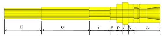
Fig. 5Mesh of the shaft finite element model
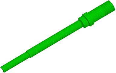
Fig. 6Mesh of the toolholder finite element model
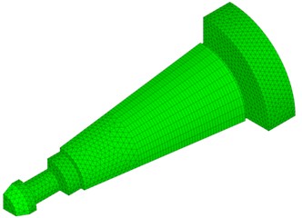
Fig. 7The drawbar mechanism modeling with lumped mass
In the material properties, the Young’s modulus of shaft is 2.1×10¹¹ N/m2 and density 7950 kg/m3. The Poisson’s ratio is 0.333. The material properties of toolholder are same as shaft. The contact area is defined after the basic model is established. In the finite element contact analysis, two end surfaces of the sensing nut and toolholder are fixed. The augmented Lagrange method is chosen as solver, contact detection is located at Gauss point. After the contact static analysis, the finite element model with pre-stress is constructed. Then the solver is change to subspace and finite element modal analysis is conducted. In order to verify the finite element modal analysis results, the experimental modal testing is performed to obtain the natural frequencies of the shaft-toolholder system. An accelerometer is attached to the assembly at location 14 as shown in Fig. 8. There are 15 locations, at each of which a hammer is used to create excitation to obtain frequency response functions. The natural frequencies are estimated by using ME’scopeVES software. The natural frequencies obtained by the two methods are compared as shown in Table 2. In this study, the natural frequencies obtained from finite element model and modal testing are compared. The percentage errors of natural frequencies are all less than 4 %. The differences are reasonable. From the contact analysis, the stress distribution at the contact area of the shaft-taper hole and the outer diameter of toolholder are shown in Fig. 9 and 10. The stress on the outer surface of toolholder is about –0.584×10⁷ N/m2. The minus sign denotes the stress is compressed. The stress distributions are uniform at the contact area. It is noted that a stress concentrated phenomenon is to take place at the location corresponding to the inner end of the shaft-taper hole. The stress concentrated phenomenon is also to take place at the inner end of the shaft-taper hole.
Fig. 8Fifteen locations where excitation is created by a hammer for modal testing
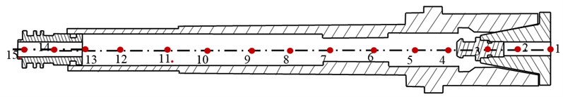
Fig. 9The stress distribution of shaft-taper hole
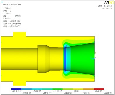
Fig. 10The stress distribution of outer diameter of toolholder
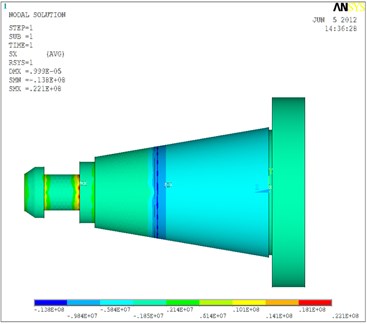
Table 2The comparison of natural frequencies for the shaft-toolholder system
Natural frequency (Hz) | Methods | ||
Modal testing | Finite element modal analysis | ||
For shaft-toolholder system | 1st | 989 | 1029 |
2nd | 2671 | 2596 | |
The shaft-taper hole and toolholder is combined using clamping force provided by the disc springs. The connection is formed from oblique cone geometry. In order to understand the effect of the cone on the clamping force, the cone area of oblique plane (as shown in Fig. 11) must be obtained firstly and is related to the surface pressure and friction force. The cone surface area can be calculated from:
Fig. 11Schematic of cone surface
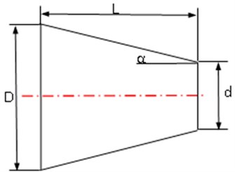
Fig. 12Schematic of the shaft-taper hole
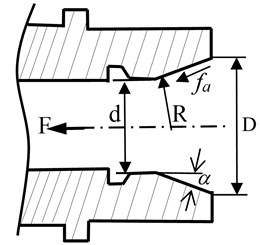
The surface pressure and friction force will be changed as the cone angle. The relationship of the clamping force and the normal force (as shown in Fig. 12) can be obtained from the static equilibrium equation:
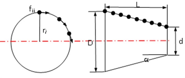
The surface friction force between the shaft taper hole and toolholder is to provide the necessary torque to resist the cutting force. In fact, the normal forces of cone surface are changed due to different sectional area. In this study, the torque provided by the surface friction force between the shaft taper hole and toolholder can be obtained by multiply normal force of node at the cone surface with the sectional radius as shown in Fig. 13. Then the friction torque () can be calculated from:
Fig. 13Schematic of the calculation of friction torque
In this paper, four different clamping forces and three coefficients of friction are investigated. The results of calculated friction torque with rotational speed 0 rpm are shown in Table 3. Finally, the rotary speed effects will be considered in the analysis, since the shaft-toolholder system is always used under a rotating speed. The compared results of friction torque with rotational speed 30,000 rpm are shown in Table 4. It is noted that the friction torque is on the decrease with the rotation speed is increased because the deformations of the shaft-taper hole and toolholder are inconsistent. For example, with clamping force 150 kgf and coefficient of friction 0.029, the friction torque is 2.53 N.m for 0 rpm and 2.51 N.m for 30,000 rpm.
Table 3The results of calculated friction torque with different clamping force and coefficient of friction
Coefficient of friction () | Friction torque (N.m) for 0 rpm | |||
Clamping force 100 kgf | Clamping force 150 kgf | Clamping force 200 kgf | Clamping force 250 kgf | |
0.029 | 1.69 | 2.53 | 3.38 | 4.23 |
0.0745 | 3.44 | 5.15 | 6.87 | 8.58 |
0.12 | 4.56 | 6.93 | 9.23 | 11.55 |
Table 4The results of calculated frictional torque with different clamping force and coefficient of friction
Coefficient of friction () | Friction torque (N.m) for 30000 rpm | |||
Clamping force 100 kgf | Clamping force 150 kgf | Clamping force 200 kgf | Clamping force 250 kgf | |
0.029 | 1.66 | 2.51 | 3.36 | 4.20 |
0.0745 | 3.14 | 5.13 | 6.62 | 8.50 |
0.12 | 4.48 | 6.87 | 8.91 | 11.30 |
4. Conclusions
In this study, the contact analysis of shaft-toolholder assembly by using finite contact element is conducted firstly, then the finite element modal analysis of shaft-toolholder assembly with pre-stress is calculated, and the results obtained from finite element modal analysis is verified with those obtained from experimental modal testing for guaranteeing the accuracy of modeling. Finally the results of finite element contact analysis for the friction torques with different clamping force, coefficient of friction and rotation speed are calculated. Several conclusions can be made as follows:
1. In this study, the modeling for the shaft-toolholder system is proposed. The percentage errors of natural frequencies are all less than 4 %. The differences are reasonable. Therefore, the proposed methodology of modeling for the finite element analysis of the shaft-toolholder assembly is effective and accurate.
2. The clamping force and the coefficient of friction have significant effects on the finite element contact analysis. The two facts must be addressed in the process of analysis such that the analysis results agree with that of real system.
3. The deformations are inconsistent between the shaft-taper hole and toolholder when the spindle speed is taken into account. It will cause the contact condition becomes incomplete and has a decrease in the friction torque.
References
-
Hughes T. J. R., Taylor R. L., Sackman J. L., Curnier A., Kanoknukulchai W. A finite element method for a class of contact-impact problems. Comput. Methods Appl. Mech. Eng., Vol. 8, 1976, p. 249-276.
-
Oysu C., Fenner R. T. Coupled FEM-BEM for elastoplastic contact problems using Lagrange multipliers. Applied Mathematical Modelling, Vol. 30, 2006, p. 231-247.
-
Gonzalez J. A., Park K. C., Felippa C. A., Abascal R. A formulation based on localized Lagrange multipliers for BEM–FEM coupling in contact problems. Comput. Methods Appl. Mech. Eng., Vol. 197, 2008, p. 623-640.
-
Ju S. H., Stone J. J., Rowlands R. E. A new symmetric contact element stiffness matrix for frictional contact problems. Computers & Structures, Vol. 54, Issue 2, 1995, p. 289-301.
-
Ezawa Y., Okamoto N. Development of contact stress analysis programs using the hybrid method of FEM and BEM. Computers & Structures, Vol. 57, Issue 4, 1995, p. 691-698.
-
Ertürk A., Özgüven H. N., Budak E. Analytical modeling of spindle-tool dynamics on machine tools using Timoshenko beam model and receptance coupling for the prediction of tool point FRF. International Journal of Machine Tools & Manufacture, Vol. 46, 2006, p. 1901-1912.
-
Ertürk A., Özgüven H. N., Budak E. Effect analysis of bearing and interface dynamics on tool point FRF for chatter stability in machine tools by using a new analytical model for spindle-tool assemblies. International Journal of Machine Tools & Manufacture, Vol. 47, 2007, p. 23-32.
-
Wock E. H. M., Spachtholz G. 3- and 4-contact point spindle bearings – a new approach for high speed spindle systems. CIRP Annals – Manufacturing Technology, Vol. 52, 2003, p. 311-316.
-
Hsu M. C., Junz Wang J. J. Dynamic analysis of milling system with high speed built-in-motor spindle. M.S. dissertation, National Cheng Kung University, Tainan, Taiwan, 2003, (in Chinese).
-
Chen H. J., Fang J. The dynamic analysis for the toolholder mechanism in a build-in spindle. M.S. dissertation, Feng Chia University, Taichung, Taiwan, 2009, (in Chinese).
-
Shieh L. C., Lin B. T. The effects of centrifugal deformation on the high-speed spindle. M.S. dissertation, National Kaohsiung First University of Science and Technology, Kaohsiung, Taiwan, 2002, (in Chinese).
-
Wang J. H. Investigation of the tool holder system with a taper angle 7:24. International Journal of Machine Tools & Manufacture, Vol. 34, Issue 8, 1994, p. 1163-1176.
-
Li H., Shin Y. C. Analysis of bearing configuration effects on high speed spindles using an integrated dynamic thermo-mechanical spindle model. International Journal of Machine Tools & Manufacture, Vol. 44, 2004, p. 347-364.
-
Chen C. H., Wang K. W., Shin Y. C. An integrated approach toward the dynamic analysis of high speed spindles, part I: system model. Journal of Vibration and Acoustics, Vol. 116, 1994, p. 506-513.
-
Chen C. H., Wang K. W., Shin Y. C. An integrated approach toward the dynamic analysis of high speed spindles, part II: dynamics under moving end load. Journal of Vibration and Acoustics, Vol. 116, 1994, p. 514-522.
-
Wang J. S., Sun J. H. Finite element analysis for the put-in force of drawbar mechanism in high speed air spindle. M.S. dissertation, National Kaohsiung First University of Science and Technology, Kaohsiung, Taiwan, 2001, (in Chinese).
-
Namazi M., Altintas Y., Abe T., Rajapakse N. Modeling and identification of tool holder-spindle interface dynamics. International Journal of Machine Tools & Manufacture, Vol. 47, 2007, p. 1333-1341.
-
Sun H. T., Su C. T. Analysis of clamping force and contact pressure of the high speed spindle. M.S. dissertation, National Kaohsiung First University of Science and Technology, Kaohsiung, Taiwan, 2007, (in Chinese).
-
Hwang Y. W., Sen C. T. Type synthesis for tool holding device and design for the power draw bar of spindle. M.S. dissertation, National Chung Cheng University, Tainan, Taiwan, 1997, (in Chinese).
-
Chen S. Y., Kung C., Hsu J. C. Dynamic analysis of a rotary hollow shaft with hot-fit part using contact elements with friction. Transactions of the Canadian Society for Mechanical Engineering, Vol. 35, Issue 3, 2011, p. 461-474.
-
Chen S. Y. The dynamic analyses and verifications of a hollow shaft with hot-fit component using 3D finite contact element. Transactions of the Canadian Society for Mechanical Engineering, Vol. 37, Issue 1, 2013, p. 21-38.
About this article
This support of the National Science Council (NSC) under the Grant NSC102-2221-E-269-004 in Taiwan is gratefully acknowledged. Also the authors are grateful to the assistance by Parfaite Company on offering the drawings, parts/components, and working assemblies.
