Abstract
The dynamic behavior of micro circular plate electrostatic devices is not easily analyzed using traditional methods such as perturbation theory or Galerkin approach method due to the complexity of the interactions among the electrostatic coupling effect, the residual stress and the nonlinear electrostatic force. Accordingly, the present study proposes a approach for analyzing the dynamic response of such devices using a hybrid numerical scheme comprising the differential transformation method and the finite difference method. The feasibility of the proposed approach is demonstrated by modeling the dynamic response of a micro circular plate actuated by a DC voltage. The numerical results for the pull-in voltage are found to deviate by no more than 0.27 % from those derived in the literature using various computational methods. Thus, the basic validity of the hybrid numerical scheme is confirmed. Moreover, the effectiveness of a combined DC/AC loading scheme in driving the micro circular actuator is examined. It is shown that the use of an AC actuating voltage in addition to the DC driving voltage provides an effective means of tuning the dynamic response of the micro circular plate.
1. Introduction
Micro-electro-mechanical systems (MEMS) devices have found widespread use throughout industry for such applications as accelerometers and pressure sensors [1], micro-scale actuators [2], electrostatic rotary comb actuators [3], and so on. Various schemes have been proposed for driving MEMS devices, including electrostatic actuation [4], thermal actuation, piezoelectric actuation [5] and electromagnetic actuation [6]. Among these various methods, electrostatic actuation is the most commonly preferred due to its simplicity and high efficiency [7]. Actually, in the electrostatic actuation of a micro-structure system, the electrostatic force is produced from the voltages of two electrodes. If the electrostatic force is greater than the elastic restoring force of the micro-structure system, this represents an unstable phenomenon [8], and the two electrodes attract and come into contact with each other suddenly. The critical value of the voltage is defined as the pull-in voltage, which has a tremendous influence on the electrostatic device. For example, the electrostatic device is regarded as an actuator when the operation voltage is greater than the pull-in voltage and the upper electrode can be attracted to the fixed bottom electrode very quickly; therefore, the pull-in voltage limits the operation range of the actuator. The pull-in behavior phenomenon, however, can be used in the design of such components as switches [9] and relays; moreover, it could be used to measure Young’s modulus and residual stress values [8]. Hence, in designing electrostatically-actuated MEMS devices, a thorough understanding of the dynamic behavior of the device structure is required such that the pull-in event can be either avoided or induced, as required. Abdel-Rahman et al [10] proposed a nonlinear model for characterizing the mechanical behavior of electrostatically-actuated micro-beams Hung [11] examined the feasibility of using the leveraged bending and strain-stiffening methods to extend the travel range of analog-tuned electrostatic actuators prior to pull-in.
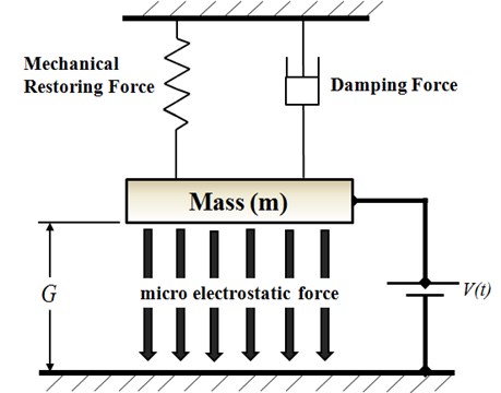
Various researchers have investigated the use of hybrid DC/AC schemes in driving electrostatically-actuated MEMS devices [12-15]. Consider the lumped model of a parallel plate capacitor shown in Fig. 1, in which the initial gap height between the two plates is denoted by . The dynamic behavior of the system is governed by the micro electrostatic force, the mechanical restoring force and the damping force together govern the dynamic behavior of micro system. The micro electrostatic force is determined by the driving voltage , which comprises both a DC voltage component and an AC voltage component. The DC component offsets the upper plate to a new equilibrium position, while the AC component causes the plate to vibrate around this newly established equilibrium position. Younis et al [13] proposed a novel RF MEMS switch actuated using a combined DC/AC loading scheme. It was shown that an appropriate specification of the magnitude and frequency of the AC voltage enabled the driving voltage required to induce the pull-in event to be significantly reduced. Younis [14] examined the dynamic behavior of micro-beams subject to combined DC/AC loading and derived analytical expressions for the micro-beam motion under primary resonance conditions. In general, MEMS devices with a circular plate configuration have a better structure flexibility than those with a rectangular plate configuration due to a lack of sharp edges and a lower residual stress after multiple depositions [15].
Fig. 1Lumped model of parallel-plate capacitor
Differential transformation theory was originally proposed by Zhao as a means of solving linear and nonlinear initial value problems in the circuit analysis domain. However, in more recent years, researchers have extended its use to the analysis of a variety of initial value problems in the mechanical engineering field. For example, Chen et al. [16] showed that the combined differential transformation and finite difference method provides a precise and computationally-efficient means of analyzing the nonlinear dynamic behavior of fixed-fixed micro-beams. The same group also used the hybrid method to analyze the nonlinear dynamic response of an electrostatically-actuated micro circular plate subject to both effects of residual stress and a uniform hydrostatic pressure on the upper surface [17-18, 20]. A numerical investigation was performed into the entropy generated within a mixed convection flow with viscous dissipation effects in a parallel-plate vertical channel using differential transformation method by Chen et al. [19].
2. Differential transformation theory
The basic principles of the differential transformation method are introduced below. If is an analyzable function in time domain , a definition of the differential transformation of at in the domain is:
where belongs to the set of non-negative integers denoted as the domain, is the transformed function in the transformation domain, otherwise called the spectrum of at in the domain, is the weighting factor, and is regarded as a kernel corresponding to . Both and are non-zero and is an analyzable function in time domain . Therefore, the differential inverse transformation of can be described as:
If and where is the time interval. Let Eq. (1) then becomes:
The differential inverse transformation of can then be expressed as below by Eq. (2):
Substituting Eq. (3) into Eq. (4) gives:
Eq. (5) can be derived by Taylor series expansion. Therefore, the main basic operation properties of the differential transform are as listed below:
(a) Linearity operation:
where denotes the differential transform and and are any real number.
(b) Differential operation:
where denotes the differential transform and is the order of differentiation [16-19].
3. Dynamic modeling of micro circular plate
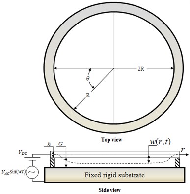
The analysis performed in this study considers the micro circular plate shown in Fig. 2. As shown, the upper plate is actuated by a driving voltage , where is the DC polarization voltage, is the magnitude of AC voltage, and is the excitation frequency. At a certain critical value of the driving voltage, the magnitude of the electrostatic force between the upper and lower plates exceeds the restoring force within the upper, movable plate, and thus a pull-in occurs.
Fig. 2Schematic illustration showing electrostatic actuation of micro circular plate
The governing equation is therefore given as [12]:
where , and are represent the permittivity of free space, the thickness of the micro circular plate, and the initial gap height between the upper and lower plates, respectively. In addition, is the voltage between the two plates, (i.e., ), is the density of the micro circular plate, and is the transverse deflection of the micro circular plate at a distance from the center of the plate. Note that is a function only of the position and the time , i.e., . In other words, the symmetry transverse deflection of micro circular plate is irrelevant to polar coordinate . Finally, is the uniform hydrostatic pressure acting on the upper surface of the plate, is the residual stress within the plate, and is the flexural rigidity of the plate, i.e.:
where and are the Poisson ratio and Young’s modulus of the upper circular plate, respectively. The boundary conditions for the governing equation of motion of the micro circular plate for are defined as follows:
where is the radius of the micro circular plate. (Note that Eq. (10) assumes that the plate is clamped at its edges). Finally, the initial condition is defined as:
4. Application of hybrid method to solution of governing equation of motion
For analytical convenience, let the the transverse displacement of the micro circular plate be normalized with respect to the initial gap between the electrodes. Furthermore, let the radial distance position be normalized with respect to the radius of the micro circular plate, and let time be normalized with respect to a time constant , where is defined as . Finally, let the excitation frequency be normalized by taking the product of and the time constant , i.e.:
Let the following parameters be defined:
Substituting Eqs. (12) and (13) into Eqs. (8), (10) and (11), the dimensionless governing equation of motion for the micro circular plate is obtained as:
The corresponding dimensionless boundary conditions are given as follows:
Finally, the initial condition is equal to:
The nonlinear governing equation of motion for the micro circular plate (Eq. (14)) is solved using the hybrid differential transformation and finite difference method described in [16-19]. The solution procedure commences by discretizing the equation of motion with respect to the time domain using the differential transformation method. In accordance with the hybrid numerical method, the transverse displacement of the micro plate is then discretized spatially in the radial direction using the finite difference approximation method based on fourth-order and second-order accurate central difference formulae.
5. Numerical results and discussion
In performing the comparison, two models of the micro circular actuator are considered (see Table 1). As shown in Table 2, the pull-in voltage of the Model 1 micro circular plate is found to be 363 V when using the hybrid differential transformation and finite difference method. The equivalent values of the pull-in voltage computed using Osternberg’s model [18] and the reduced-order model [18] are 362 V and 364 V, respectively. In other words, the predicted value of the pull-voltage obtained using the hybrid method deviates by just 0.27 % from the results presented in [18].
Table 1Material and geometry parameters of micro circular plate models
Parameters | Model 1 | Model 2 |
Young’s modulus ( / GPa) | 169 | 130 |
Poisson’s Ratio () | 0.3 | 0.23 |
Density ( / Kg/m3) | 2.33×10³ | 2.33×10³ |
Permittivity of free space ( / F/m) | 8.8542×10⁻¹² | 8.8542×10⁻¹² |
Thickness of circular plate ( / μm) | 20 | 1 |
Initial gap ( / μm) | 1 | 1 |
Radius of circular plate ( / μm) | 250 | 200 |
Table 2Comparison of present analytical results and literature results for pull-in voltages
Analytical results | Deviation | ||||
Hybrid method (H.M.) (Model 1) | Osterberg’s model [15] | Reduced-order model [15] | (%) | (%) | |
Pull-in Voltage (V) | 363 | 362 | 364 | 0.27 | 0.27 |
Figure 3 shows the variation of the center-point deflection of the Model 2 circular plate over time given AC voltages of 1.61 V, 1.62 V and 1.63 V, respectively. Note that the DC voltage is equal to 4.5 V, the residual stress is equal to , and the AC voltage frequency is equal to . The results clearly show that for an AC voltage lower voltage of 1.62 V, the micro circular plate oscillates in a stable manner about the equilibrium deflection point. However, when the AC voltage is increased to 1.63 V, the pull-in phenomenon occurs, and the micro circular plate makes transient contact with the lower electrode.
Fig. 3Variation of dimensionless center-point displacement over time for AC voltages of 1.61 V, 1.62 V and 1.63 V, respectively, (note that DC voltage = 4.5 V and ω-=1)
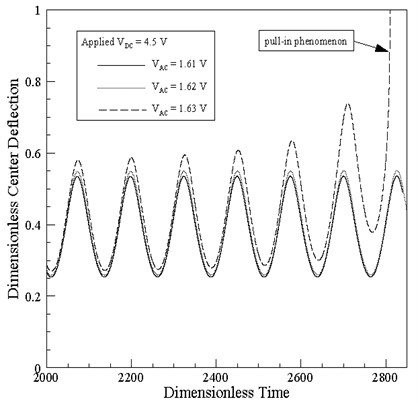
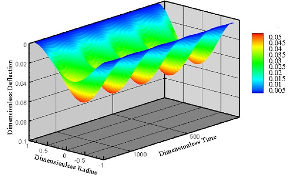
Figure 4 shows the deformation over time of the Model 2 micro circular plate given an AC voltage of 0.5 V, a dimensionless excitation frequency of , and a DC voltage of 2 V. As stated previously, the transverse displacement of the micro circular plate depends only on radial position and the time. In other words, the displacement is independent of the polar coordinate . As a result, the micro circular plate oscillates in a stable fashion.
Fig. 4Deformation of micro circular plate given DC voltage of 2 V and AC voltage of 0.5 V, (note that ω-=1/2)
6. Conclusions
This study has analyzed the nonlinear dynamic behavior of an electrostatically-actuated micro circular plate using a hybrid numerical scheme comprising the differential transformation method and the finite difference method. The validity of the proposed scheme has been confirmed by comparing the predicted value of the pull-in voltage for the plate with the results presented in the literature. Finally, it has been shown that the use of an AC actuating voltage with an appropriate magnitude in addition to the DC driving voltage provides an effective means of tuning the dynamic response of the micro circular plate. Overall, the numerical results presented in this study show that the hybrid differential transformation method and finite difference method provides an accurate and computationally-efficient means of analyzing the nonlinear dynamic behavior of the micro circular plate structures used in many of today’s MEMS-based actuator systems.
References
-
Bosc J. M., Guo Y., Sarihan V., Lee T. Accelerated life testing for micro-machined chemical sensors. IEEE Transactions on Reliability, Vol. 47, Issue 2, 1998, p. 135-141.
-
Zhu Y., Espinosa H. D. Effect of temperature on capacitive RF MEMS switch performance – a coupled-field analysis. Journal of Micromechanics and Microengineering, Vol. 14, Issue 8, 2004, p. 1270-1279.
-
Maluf N. I., Reay R. J., Kovacs G. T. A. High-voltage devices and circuits fabricated using foundry CMOS for use with electrostatic MEM actuators. Sensors and Actuators A, Vol. 52, 1996, p. 187-192.
-
Rezazadeh G., Tahmasebi A., Zubstov M. Application of piezoelectric layers in electrostatic MEM actuators: controlling of pull-in voltage. Microsystem Technologies, Vol. 12, Issue 12, 2006, p. 1163-1170.
-
Luharuka R., LeBlanc S., Bintoro J. S., Berthelot Y. H., Hesketh P. J. Simulated and experimental dynamic response characterization of an electromagnetic microvalve. Sensors and Actuators A, Vol. 143, 2008, p. 399-408.
-
Tong P., Huang W. Large deflection of thin plates in pressure sensor applications. Journal of Applied Mechanics, Vol. 69, Issue 6, 2002, p. 785-789.
-
Varadan V. M., Vinoy K. J., Jose K. A. RF MMES and their applications. Wiley, New York, 2003.
-
Osterberg P. M., Senturia S. D. M-test: a test chip for MEMS material property measurement using electrostatically actuated test structures. Journal of Microelectromechanical Systems, Vol. 6, Issue 2, 1997, p. 107-118.
-
Wong J. E., Lang J. H., Schmidt M. A. An electrostatically actuated MEMS switch for power applications. The IEEE MEMS Conference, Miyazaki, Japan, 2000, p. 633-638.
-
Abdel-Rahman E. M., Younis M. I., Nayfeh A. H. Characterization of the mechanical behavior of an electrically actuated microbeam. Journal of Micromechanics and Microengineering, Vol. 12, Issue 6, 2002, p. 759-766.
-
Hung E. S., Senturia S. D. Extending the travel range of analog-tuned electrostatic actuators. Journal of Microelectromeehanieal Systems, Vol. 8, Issue 4, 1999, p. 497-505.
-
Nayfeh A. H., Younis M. I., Abdel-Rahman E. M. Reduced-order models for MEMS applications. Nonlinear Dynamics, Vol. 41, Issue 1-3, 2005, p. 211-236.
-
Younis M. I., Abdel-Rahman E. M., Nayfeh A. H. Dynamic simulations of a novel RF MEMS switch. NSTI-Nanotech, Vol. 2, 2004, p. 287-290.
-
Younis M. I. Investigation of the mechanical behavior of microbeam-based MEMS devices. Master of Science Thesis, Virginia Polytechnic Institute and State University, 2001.
-
Vogl G. W. V., Nayfeh A. A reduced-order model for electrically actuated clamped circular plates. Journal of Micromechanics and Microengineering, Vol. 15, Issue 4, 2005, p. 684-690.
-
Chen C. K., Lai H. Y., Liu C. C. Application of hybrid differential transformation / finite difference method to nonlinear analysis of micro fixed-fixed beam. Microsystem Technologies, Vol. 15, Issue 6, 2009, p. 813-820.
-
Chen C. K., Lai H. Y., Liu C. C. Nonlinear micro circular plate analysis using hybrid differential transformation / finite difference method. CMES: Computer Modeling in Engineering & Sciences, Vol. 40, Issue 2, 2009, p. 155-174.
-
Liu C. C., Yang S. C., Chen C. K. Nonlinear dynamic analysis of micro cantilever beam under electrostatic loading. Journal of Mechanics, Vol. 28, 2012, p. 559-566.
-
Chen C. K., Lai H. Y., Liu C. C. Numerical analysis of entropy generation in mixed convection flow with viscous dissipation effects in vertical channel. International Communications in Heat and Mass Transfer, Vol. 38, 2011, p. 285-290.
-
Liu C. C., Chen C. K. Modeling and simulation of nonlinear micro-electromechanical circular plate. Smart Science, Vol. 1, Issue 1, 2013, p. 59-63.
About this article
The authors gratefully acknowledge the financial support provided to this study by the National Science Council of Taiwan under Grant Number NSC 101-2221-E-018-007.
