Abstract
A nonlinear rotor-seal-bearing system model, including the Muszynska nonlinear seal force model and nonlinear oil-film force model based on short bearing assumption, is proposed in this paper. The non-dimensional dynamic motion equations of the system are also established and solved by fourth order Runge-kutta method. The nonlinear dynamic characteristics of the system are analyzed with the help of bifurcation diagrams, spectrum waterfall diagrams, axis orbit diagrams, Poincaré maps and amplitude spectrums. The effect of rotor speed, seal clearance, seal length and seal radius on the nonlinear characteristics of the system is also explored. The genetic algorithm (GA) is applied to optimize the stability of the system. The numerical results demonstrate that the rotor-seal-bearing system contains many motion forms, such as periodic, multi-periodic and quasi-periodic motions. Lower rotor speed, proper seal clearance and seal radius, larger seal length are of benefit to the stability of rotor-seal-bearing system. The minimum instability rotor speed changing from 1970 rad/s to 2110 rad/s indicates the GA is an effective optimization method of improving the stability of rotor-seal-bearing system.
1. Introduction
With the fast development of rotating machinery, the improvement of safety reliability, stability and efficiency of rotating machinery have resulted in higher rotor speed and more stringent working conditions. Along with the higher demands, some nonlinear vibration phenomena occur and the linearized analysis could not explain the sophisticated and complex motions in rotating machinery [1]. The external excitations, such as the oil-film force of journal bearings or rolling bearings, the fluid exciting force inside the seal structure between a stator and rotor, the rubbing force and so on, are directly key factors that may induce instability in modern rotating machinery.
Up to now, many researches and numerical calculations have been carried out to analyze the nonlinear dynamic characteristics of rotor system considering the external excitations. Zhang et al. [2] solved the periodic solutions of the generator bearing-rotor system with a coupled nonlinear vibration model of the oil film force and electromagnetic force by using an improved shooting method. They also obtained the vibration response characteristics and instability margin in a typical winding inter-turn short circuit fault. Wang et al. [3] researched the nonlinear coupling effects of seal force and air-film bearing force, and got the best seal length area and the bifurcation characteristics of a high-speed centrifugal compressor with a labyrinth seal and two air-film journal bearings. But it’s a pity that, the length was got under the condition of specific pressure drop and seal length. Muszynska et al. [4, 5] proposed a new nonlinear seal force model which considered the circulating velocity as the key factor affecting the stability of the rotor system and represented that the rotor stability is an entire rotating system property. Based on the Hamilton principle and the finite element method, a new dynamic model of a rotor system considering the coupled effects of the nonlinear oil film force, the nonlinear seal force, and the mass eccentricity of the disc was established by Li et al. [6, 7] to analyze the dynamic behavior of a rotor system. But the new model ignored the effect of rotational displacements. Akhmetkhanov et al. [8] studied the flow-coupled vibrations of an unbalanced rotor with a floating sealing ring and got the dynamic characteristics both of non-impact and impact regimes. The results pointed out that the impact regimes are very dangerous for the safety of the system. Al-Nahwi et al. [9] employed a Jeffccot rotor system and a reduced-order Moore-Greitzer flow field model to investigate the interaction between steam excitation and the rotor system and found the interaction was largely governed by the tip clearance and the ratio of fluid mass to rotor mass. Hua et al. [10] used the Muszynska nonlinear seal model and an efficient high-precision direct integration method to investigate the nonlinear dynamic phenonmena in the unbalanced rotor-seal system. However, the bearing effect, which was a very important factor, was ignored. Shen et al. [11, 12] researched the effect of labyrinth seal force on nonlinear dynamics and stability of the rotor-bearing-seal system both theoretically and experimentally. A piecewise linear two degrees-of-freedom rotor system model considering bearing clearance and stabilising rods was proposed by Karlberg et al. [13] to evaluate effects of applying stabilising rods on the nonlinear vibrations of the rotor system. Ma et al. [14] investigated effects of the nonlinear seal force and oil-film force on the first and second mode instabilities of a rotor-bearing-seal system considering the lumped mass model and the gyroscopic effect under two loading conditions.
It should be noted that in all the researches mentioned above, the nonlinear dynamics of rotor-seal systems or rotor-seal-bearing systems were analyzed under specific seal structures, bearing structures or operating conditions and few literatures paid attention to the stability optimization of rotor-seal-bearing system.
With the higher demands of energy-saving, efficiency and stability of the rotor-seal-bearing system, it’s of vital importance to improve the stability of the rotating machinery. In this paper, a nonlinear rotor-seal-bearing system model, considering the Muszynska nonlinear seal force model and a nonlinear oil-film force model under short bearing assumption, is established and the differential motion equations are solved by the fourth order Runge-Kutta method. The effects of seal parameters on the nonlinear characteristics are also discussed and the nonlinear characteristics of the rotor-seal-bearing system are presented in the form of bifurcation diagrams, spectrum waterfall diagrams, axis orbit diagrams, Poincaré maps and amplitude spectrums. In order to improve the minimum instability speed and optimize the stability of the system, the GA is also applied to find the optimal parameters of seal structure, the optimization results indicate that the optimized minimum instability speed is obviously larger than that under the original condition, which means GA is an effective method to analysis and optimize the stability of rotor-seal-bearing system.
2. Dynamic model of the rotor-seal-bearing system
Fig. 1Rotor-seal-bearing system
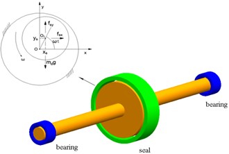
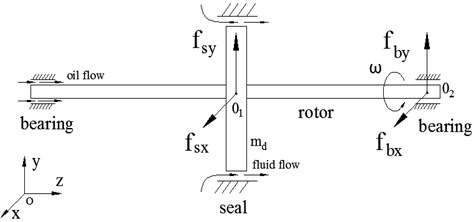
Fig. 2Schematic diagram of rotor-seal-bearing system
The rotor-seal-bearing system, in which the rotor is supported by two oil-film bearings and a seal, is shown in Fig. 1, and are the geometric center of seal and the disc respectively, is the rotation speed of rotor, is the mass of disc, is the seal force in the -direction, and is the seal force in the -direction. In the system, the two bearings are located at the both ends of the rotor, the disc is located at the midpoint of the centerline of bearings. The subscript ‘’ denotes the seal.
Fig. 2 shows the schematic diagram of rotor-seal-bearing system. Considering that the two bearings are exactly symmetrical, we only investigated the vibration characteristics of the right bearing. is the geometric center of the rotor at the position of bearing, is the oil-film force of bearing in the -direction, and is the oil-film force of bearing in the -direction. The subscript ‘’ denotes the bearing.
2.1. Oil-film force of the bearing
In order to guarantee the convergence and accuracy of the oil-film force, the nonlinear dynamic oil-film model is established based on short bearing theory, which is used to describe the nonlinear oil-film force of the bearing [15]. The non-dimensional differential equation for the oil-film force in the bearing can be expressed as:
where:
where , are the non-displacement of the .
2.2. Nonlinear seal force
Muszynska's nonlinear seal fluid dynamic force model [4], which has been widely used to describe the nonlinear characteristics of seal force, is applied in this paper to determine the nonlinear seal force acting on the disc. The nonlinear seal force can be expressed as follows:
where 0.5-3, 0-1, 0.5, is the radial clearance of the seal, and are the displacement of the and , and are equivalent stiffness, equivalent mass, equivalent damping, respectively. Furthermore, they were given by Childs [16].
2.3. System motion equations
The dynamic motion equations of the rotor-bearing-seal system shown in Fig. 1 and Fig. 2 can be deduced as follows:
where , are the damping of rotor and bearing, is the stiffness of rotor, is the eccentricity of disc, is the time, is the acceleration of gravity, is the mass of the rotor at the bearing.
Introducing the following non-dimensional transforms:
where is the radial clearance of the bearing, , are the non-displacement of the , is the oil viscosity, is the radius of the bearing, is the length of the bearing, and other parameters have been mentioned above.
Substituting the Eqs. (1), (6) and non-dimensional transforms mentioned above into Eq. (7), the non-dimensional dynamic motion equations can be transformed as follows:
Eq. (8) represents the strong nonlinear characteristics of the rotor-seal-bearing system. The non-dimensional second order differential motion equations are difficult to solve by conventional perturbation methods, therefore the fourth order Runge-Kutta method is applied to obtain the numerical response solutions of the system.
3. Nonlinear characteristics of the rotor-seal-bearing system
The bifurcation diagrams and spectrum waterfall diagrams show the variation course of the motion of the system. Axis orbit diagrams, Poincaré maps and amplitude spectrums are also used to analyze the nonlinear characteristics of the rotor-seal-bearing system. The main parameters of the rotor-seal-bearing system are shown in Table 1 and the experimental coefficients of the seal are listed in Table 2.
Table 1Main parameters of the rotor-seal-bearing system
Parameters | Value | Parameters | Value | Parameters | Value | Parameters | Value |
(kg) | 50 | (m) | 0.015 | (N·s/m) | 3000 | (Pa·s) | 0.02 |
(m) | 0.0004 | (m) | 0.025 | (N·s/m) | 1000 | (m) | 0.0004 |
(kg) | 25 | (m) | 0.0001 | (N/m) | 2×10⁷ |
Table 2Experimental coefficients of the seal
Coefficients | |||||
Values | 2 | 0.5 | 0.4 | 0.079 | –0.25 |
3.1. Influence of the rotor speed
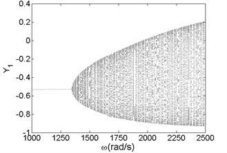
Rotor speed has significant influence on the vibration characteristics and dynamic response of the rotor-seal-bearing system. In order to investigate the effect of rotor speed on the nonlinear characteristics of the system, the rotor speed we choose ranges from 1000 rad/s to 2500 rad/s, with the rotor speed as abscissa and the dimensionless displacements as ordinates. The dimensionless time ranges from 0 to 600 and the integration step is chosen to be 2/512, i.e., within every period, there are 512 times of integral calculation. To eliminate the effect of free vibration and ensure accuracy of the results, the former half iterative results are discarded and the last half iterative results are remained for analysis.
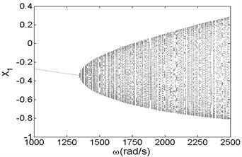
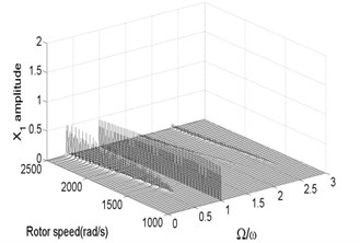
Fig. 3Bifurcation diagram a) and spectrum waterfall diagram b) in X direction
a)
b)
Fig. 4Bifurcation diagram a) and spectrum waterfall diagram b) in Y direction
a)

b)
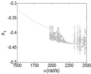
Fig. 3 and Fig. 4 are bifurcation diagrams and spectrum waterfall diagrams in and direction respectively when the rotor speed changes from 1000 rad/s to 2500 rad/s. From the bifurcation diagrams, we can see that the vibration amplitude in direction is lower than origin point because of gravity force, especially when the system is working at a low rotor speed. With the increasing of rotor speed, the vibration amplitude in and directions become larger than the original situation. It also can be known that when the rotor speed is less than 1350 rad/s, which is called minimum instability rotor speed, there is just one isolate point in the bifurcation diagrams. In spectrum waterfall diagrams, the ratio just has one component and the value is 1, which also indicates the system is in synchronous whirl motion. However, once the rotor speed exceeds 1350 rad/s, the system loses stability and turns into unstable quasi-periodic motion, and some low frequency components and high frequency components occur. As the rotor speed increases, the amplitude of low frequency components increases more obviously than that of high frequency components, which means the low frequency components have a significant effect on the nonlinear vibration of the rotor-seal-bearing system in higher rotor speed, which is consistent with numerical and experimental results of references [11-12]. Simultaneously, the ratio values of low frequency components decrease with the rotor speed increasing. In fact, not only the quasi-periodic motion, but also the multi-periodic motions, such as period-two motion (shown in Fig. 7) and other period- motions [3, 6], can be found as the rotor speed increases.
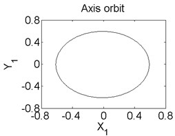
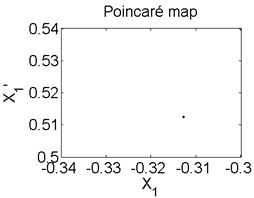
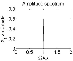
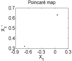
Fig. 5Axis orbit a) Poincaré map b) and Amplitude spectrum c) at ω= 1200 rad/s
a)
b)
c)
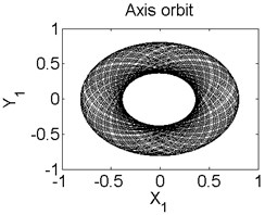
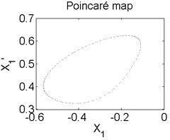
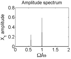
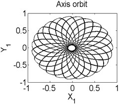
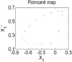
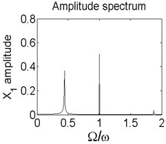
Fig. 6Axis orbit a) Poincaré map b) and Amplitude spectrum c) at ω=1550 rad/s
a)
b)
c)
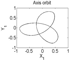
In order to better study the nonlinear characteristics of the rotor-seal-bearing system, Figs. 5-8 represent the dynamic response of the system at 1200 rad/s, 1550 rad/s, 1885 rad/s and 2150 rad/s respectively and the nonlinear vibrations of the system are analyzed by axis orbit, Poincaré map and amplitude spectrum. Fig. 5 shows that when the system operates at 1200 rad/s, the axis orbit is approximately a circle, and just an isolated enlarged point (–0.312, 0.512) exits in the Poincaré map, corresponding to 1 in the amplitude spectrum, which imply the system is in stable status. When the rotor speed changes to 1550 rad/s, considering the display of the axis orbit, the last 20 % iterative results are used in axis orbit diagram, showing in Fig. 6. The results show that the axis orbit becomes irregular, concentrated in ranging [–0.8, 0.8] in direction and direction, respectively. There is a closed curve in the Poincaré map and two frequency parts exist in the amplitude spectrum, one is 1, the other one is 0.585, there are no common divisor of the two frequency parts, which clearly indicate that the motion of the system is quasi-periodic motion. Once the rotor speed reaches to 1885 rad/s, showing in Fig. 7, the system changes from quasi-periodic motion to period-two motion, the axis orbit represents cross three heart-shaped, two isolated enlarged points in the Poincaré map. The low frequency part is half of the rotation frequency and the amplitude of this frequency part is larger compared with the previous rotor speed. Fig. 8 illustrates the dynamic response of the system at 2150 rad/s, the axis orbit becomes irregular again, the points in the Poincaré map has a trend to become a closed curve and the ratio of the low frequency part decreases to 0.44, which demonstrate that system comes back to quasi-periodic motion.
Fig. 7Axis orbit a) Poincaré map b) and Amplitude spectrum c) at ω= 1885 rad/s
a)
b)

c)
Fig. 8Axis orbit a) Poincaré map b) and Amplitude spectrum c) at ω= 2150 rad/s
a)
b)
c)
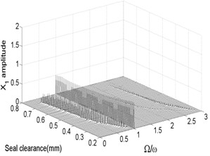
To study the specific effects of the seal parameters on the rotor-seal-bearing system, we obtained the bifurcation diagrams and spectrum waterfall diagrams of the system, where the seal clearance, seal length and seal radius are labeled as the abscissa, i.e., as variable parameters respectively.
3.2. Influence of the seal clearance
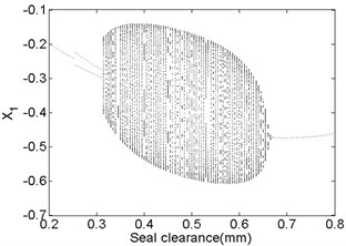
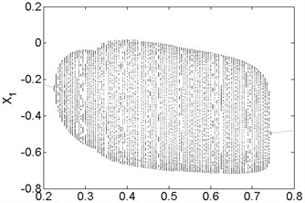
The bifurcation diagrams and spectrum waterfall diagrams are presented in Fig. 9 and Fig. 10 where the seal clearance is used as the variable parameter, ranging from 0.2 mm to 0.8 mm, and two situations under different rotor speeds are also considered. From Fig. 9, it can be known that the main motion characteristics at 1500 rad/s can be summarized as: synchronous whirl motion → period-two motion → quasi-periodic motion → synchronous whirl motion. In the spectrum waterfall diagram shows that as the seal clearance increases, some low frequency components and high frequency components occur, at first the amplitudes both of them increase and then decrease, and disappear at last. The ratio decreases from 0.75 to 0.44 with the seal clearance increasing. When the rotor speed increases to 1800 rad/s, as shown in Fig. 10, we can see that the period-two motion disappears, the range of the stable synchronous whirl motion becomes narrow and conversely the range of the quasi-periodic motion expands, ranging from 0.225 mm to 0.745 mm, which indicates that the system is easier to lose the stability in a higher rotor speed as the seal clearance changes and proper seal clearance is propitious to the improvement of system stability.
Fig. 9Bifurcation diagram a) and spectrum waterfall diagram b) at ω= 1500 rad/s
a)

b)
Fig. 10Bifurcation diagram a) and spectrum waterfall diagram b) at ω= 1800 rad/s
a)
b)
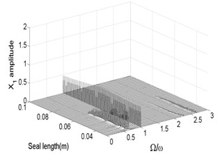
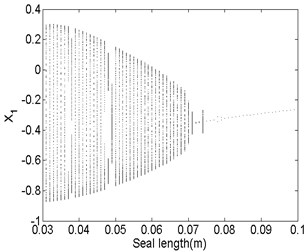
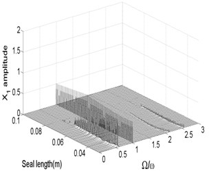
3.3. Influence of the seal length
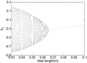
The bifurcation diagrams and spectrum waterfall diagrams are presented in Fig. 11 and Fig. 12 where the seal length is used as the variable parameter, ranging from 0.03 m to 0.1 m, and also two situations under different rotor speeds are considered. Fig. 11 shows that the stability of the system enhances with the seal length increasing at 1500 rad/s, when the seal length is less than 0.065 m, the system is in quasi-periodic motion. However, the vibration amplitude decreases as the seal length increases, this is because the effect of low frequency part on the system becomes smaller and smaller and till it disappears. When the seal length exceeds 0.065 m, the system becomes stable synchronous whirl motion and changes to be period-two motion once the seal length exceeds 0.094 m. When the rotor speed increases to 1800 rad/s, as shown in Fig. 12, the stable seal length changes from 0.65 m to 0.71 m, which implies the system is harder to be stable in a higher rotor speed as the seal length changes. The motion status of the system change frequently when the seal length excesses 0.71 m and can be summarized as: synchronous whirl motion → quasi-periodic motion → synchronous whirl motion → period-two motion → synchronous whirl motion.
Fig. 11Bifurcation diagram a) and spectrum waterfall diagram b) at ω= 1500 rad/s
a)
b)
Fig. 12Bifurcation diagram a) and spectrum waterfall diagram b) at ω= 1800 rad/s
a)
b)
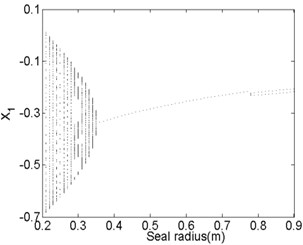
3.4. Influence of the seal radius
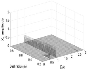
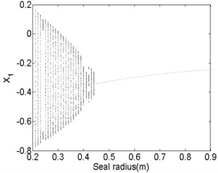
Fig. 13 and Fig. 14 show the bifurcation diagrams and spectrum waterfall diagrams where the seal radius is applied as the variable parameter, ranging from 0.2 m to 0.9 m. The different rotor speeds are also 1500 rad/s and 1800 rad/s. Totally, the nonlinear vibration characteristics of the system with the increasing of the seal radius are similar with those in previous Fig. 11 and Fig. 12, the motion status also changes from quasi-periodic motion to stable synchronous whirl motion and the system is harder to be stable in a higher rotor speed as the seal radius increases. The stable rotor speed changes from 0.35 m to 0.44 m as the rotor speed increases from 1500 rad/s to 1800 rad/s. But compared with Fig. 12 with Fig. 14, the quasi-periodic motion and period-two motion occur in a partial small range of the synchronized motion. It also can be found that the ratio of low frequency parts in the spectrum waterfall diagram are always approximately to 0.5 no matter how the seal radius changes.
Fig. 13Bifurcation diagram a) and spectrum waterfall diagram b) at ω= 1500 rad/s
a)
b)
Fig. 14Bifurcation diagram a) and spectrum waterfall diagram b) at ω= 1800 rad/s
a)
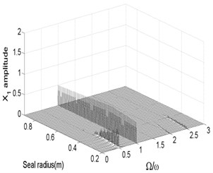
b)
4. Stability optimization of the rotor-seal-bearing system
The above results indicate that the nonlinear vibration of the rotor-seal-bearing system is complex and the system has different vibration status when it works under different parameters, such as the seal clearance, seal length, seal radius, and so on. In fact, the rotor-seal-bearing system is a sophisticated and multidimensional nonlinear dynamic system, whose nonlinear vibration characteristics are influenced by a variety of factors, such as the oil-film force of bearings, the fluid exciting force of seal, the rubbing force, etc, which means the optimization of rotor-seal-bearing system is an issue with multiple constraints. In order to enhance efficiency and safety of the system, we must choose proper parameters to make the system more stable. Considering the nonlinearity and multiple constraints problems of the system, we choose GA as the optimization method to enhance the minimum instability rotor speed. In fact, as an effective method, GA has been successfully applied to the optimization of rolling bearing, rotor structure and other engineering fields which has obtained some good results [17-20].
Fig. 15 shows the flow chart of stability optimizing of rotor-seal-bearing system. The minimum instability rotor speed is regarded as the fitness function, and the design parameters, including seal clearance, seal length and seal radius, are coded as the chromosomes of individuals. It should be noted that by providing bounds, the search space becomes narrow and leads to faster convergence, so the bounds of the design parameters are the same as previous calculating bounds.
Fig. 15Flow chart of GA for optimizing rotor-seal-bearing system
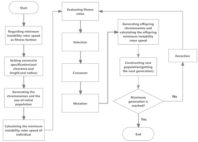
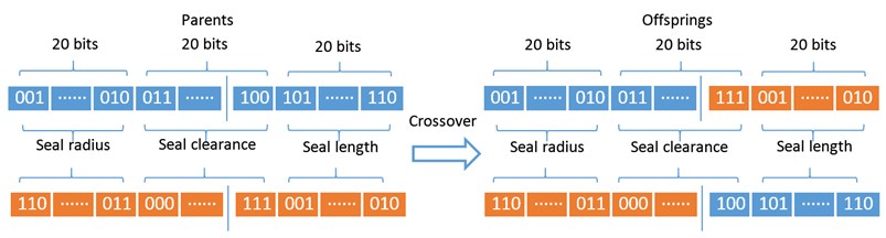
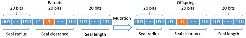
The main operations of GA are evaluation, selection, crossover and mutation. Evaluation is the operator that estimates the values of minimum instability rotor speed for each individual in the evolutional process. The selection operator determines the individuals of the population that survive to form the individuals of the next population. The selection is based on the values of minimum instability rotor speed because the individuals corresponding to greater values tend to survive. After selection, we need to use a binary code operator to code the design parameters as a binary string in which each bit represents a gene. In this paper, the binary length of each design parameter is twenty bits, which indicates the total length of a binary string, i.e. chromosome, is sixty bits. Crossover is the operator that allows producing offsprings by recombining the chromosomes of two individuals and hopes the new individuals with a higher minimum instability rotor speed than their parents. Mutation is the last main operator that creates a new offspring by changing the bit of an individual from 1 to 0 or from 0 to 1 randomly, which means each bit of each individual is possible subject to mutation. The schematic procedures of the crossover operation and mutation operation are shown in Fig. 16.
Fig. 16Schematic procedures of the crossover operation a) and mutation operation b)
a)
b)
To get the minimum instability rotor speed, we define the following equation to judge whether the rotor speed is the minimum instability rotor speed. The rotor speed is regard as the minimum instability rotor speed if it satisfies the Eq. (9):
where subscript ‘’ means every arbitrary period, and the constraint parameters, seal clearance (), seal length () and seal radius (), can be described as follows:
Based on the bounds of constraint parameters, the initial generation design variables are generated randomly for a population of 30. We choose the increment of the rotor speed as 10 rad/s. The algorithm runs with certain number of generations until the optimum solution doesn’t change with further increase in generations, which indicates that the convergence has been achieved. The GA parameters used in the paper are listed in Table 3.
Table 3GA parameters
Generation gap | Crossover probability | Mutation probability | Population size | Maximum generation |
0.95 | 0.7 | 0.01 | 30 | 50 |
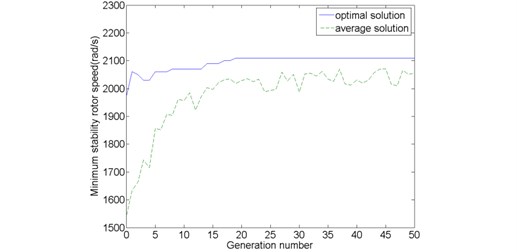
Fig. 17 shows the optimal and average fitness function values from the initial generation to maximum generation, from which we can find that the initial generation and maximum generation optimal minimum instability rotor speeds are 1970 rad/s and 1550 rad/s respectively. After 19 generations (convergence point), the optimal minimum instability rotor speed converged uniformly to about a magnitude of 2110 rad/s until the maximum generation. The average minimum instability rotor speed is obtained by dividing the sum of fitness function values in a particular generation by the population size. The speed increases fairly fast before 19 generations and tends to convergence, fluctuating around a specific value about 2300 rad/s once the genetic generation runs over the 19th generation.
Fig. 17Optimal and average fitness function values
The initial generation and maximum generation optimal instability rotor speeds and the corresponding design parameter are listed in Table 4. The optimization results illustrate that the minimum instability rotor speed enhances from 1970 rad/s to 2110 rad/s by GA. However, a point must be noted. The maximum generation optimal design parameters corresponding to the optimal minimum instability rotor speed are not just one group but several simultaneous groups. In order to highlight the optimized effects of GA, the bold fonts in the Table 4 is used as the maximum generation optimal design parameters to express the nonlinear characteristics of maximum generation and the bifurcation diagrams under initial generation and maximum generation optimal design parameters are represented in Fig. 18.
Table 4Initial generation and maximum generation optimal parameters
Minimum instability rotor speed (rad/s) | Seal radius (m) | Seal clearance (m) | Seal length (m) | |
Initial optimal generation parameters | 1970 | 0.375986 | 0.000762 | 0.081940 |
Maximum generation optimal parameters | 2110 | 0.480739 | 0.000799 | 0.052822 |
… | … | … | ||
0.465850 | 0.000799 | 0.053169 | ||
0.556060 | 0.000796 | 0.052569 |
Fig. 18Bifurcation diagrams of initial generation a) and maximum generation b)
a)
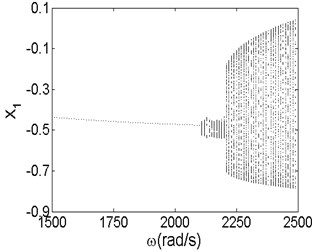
b)
The results shown in Fig. 18 illustrate that the minimum instability rotor speed changes from 1970 rad/s of initial generation to 2110 rad/s of maximum generation, which is consistent with the values in Fig. 17. The results reveal that GA is an effective method of optimizing the stability of rotor-seal-bearing system. From the bifurcation diagram of initial generation, we can see that the vibration amplitude in direction becomes larger as the rotor speed increases to 1970 rad/s. Once the rotor speed exceeds 1970 rad/s, the motion status of the system changes from stable synchronous whirl motion to quasi-periodic motion and the period-two motion exists in some partial small ranges of the quasi-periodic motion when the rotor speed changes from 2300 rad/s to 2360 rad/s. In the bifurcati on diagram of maximum generation, compared with that of the initial generation, the vibration amplitude has less change when the rotor speed is below the minimum instability rotor speed. In addition, the system makes quasi-motion when the rotor speed exceeds 2110 rad/s and no other motion patterns occurs in the bifurcation diagram, which is completely different from the initial generation. In fact, the motion patterns of rotor-seal-bearing system with different design parameters, are thoroughly different even under the same optimal minimum instability rotor speed. The results also demonstrate that the nonlinear vibration of rotor-seal-bearing system is sophisticated and optimization is necessary.
5. Conclusions
The paper deals with the nonlinear vibration characteristics and stability optimization of rotor-seal-bearing system. The nonlinear rotor-seal-bearing system, including the Muszynska nonlinear seal force model and nonlinear oil-film force model, is proposed and the non-dimensional dynamic motion equations of the system are also obtained. The fourth order Runge-kutta method is used to solve the non-dimensional motion equations and numerically determine the vibration response of the system. The influence of rotor speed, seal clearance, seal length and seal radius on the nonlinear characteristics of the rotor-seal-bearing system is also studied by bifurcation diagrams, spectrum waterfall diagrams, axis orbit diagrams, Poincaré maps and amplitude spectrums. The numerical results indicate that the rotor-seal-bearing system is a complex system with rich motion forms, including periodic motion, multi-periodic motion and quasi-periodic motion. Lower rotor speed, proper seal clearance and seal radius and larger seal length are propitious for improving the stability of the system and avoiding severe vibration. The GA is also used to optimize the system stability and the optimization results show that the minimum instability rotor speed is enhanced from 1970 rad/s to 2110 rad/s, which illustrates that GA is an effective tool to analyze and optimize the stability problem of rotor-seal-bearing system.
In fact, only the effect of seal parameters are considered in the optimization of the system in this paper, and the other factors, such as bearing, disc and so on, are still need further research. However, the above results show that the GA has positive effects on solving the stability problem of single-stage rotor-seal-bearing system or multi-stage rotor-seal-bearing system.
References
-
Noah S. T., Sundararajan P. Significance of considering nonlinear effects in predicting the dynamic behavior of rotating machinery. Journal of Vibration and Control, Vol. 1, Issue 4, 1995, p. 431-458.
-
Zhang G. Y., Wei J. C., Huang H. Z., et al. A study on the nonlinear vibration of the generator rotor based on the unbalanced electromagnetic force and the oil film force coupling model. Journal of Vibroengineering, Vol. 15, Issue 1, 2013, p. 23-36.
-
Wang Y. F., Wang X. Y. Nonlinear vibration analysis for a Jeffcott rotor with seal and air-film bearing excitations. Mathematical Problems in Engineering, Vol. 2010, p. 1-14.
-
Muszynska A., Bently D. E. Improvements in lightly loaded rotor/bearing and rotor/seal models. Journal of Vibration, Acoustics, Stress, and Reliability in Design, Vol. 110, Issue 2, 1988, p. 129-136.
-
Muszynska A., Bently D. E. Frequency-swept rotating input perturbation techniques and identification of the fluid force models in rotor/bearing/seal systems and fluid handling machines. Journal of Sound and Vibration, Vol. 143, Issue 1, 1990, p. 103-124.
-
Li W., Yang Y., Sheng D. R., et al. Nonlinear dynamic analysis of a rotor/bearing/seal system. Journal of Zhejiang University-Science A, Vol. 12, Issue 1, 2011, p. 46-55.
-
Li W., Yang Y., Sheng D. R., et al. A novel nonlinear model of rotor/bearing/seal system and numerical analysis. Mechanical and Machine Theory, Vol. 46, Issue 5, 2011, p. 618-631.
-
Akhmetkhanov R., Banakh L., Nikiforov A. Flow-coupled vibrations of rotor and seal. Journal of Vibration and Control, Vol. 11, Issue 7, 2005, p. 887-901.
-
Al-Nahwi A. A., Paduano J. D., Nayfeh S. A. Aerodynamic-rotordynamic interaction in axial compression systems – Part II: Impact of interaction on overall system stability. Journal of Turbomachinery, Vol. 125, Issue 7, 2003, p. 416-426.
-
Hua J., Swaddiwudhipong S., Liu Z. S., et al. Numerical analysis of nonlinear rotor-seal system. Journal of Sound and Vibration, Vol. 283, Issue 3-5, 2005, p. 525-542.
-
Shen X. Y., Jia J. H., Zhao M., et al. Experimental and numerical analysis of nonlinear dynamics of rotor-bearing-seal system. Nonlinear Dynamics, Vol. 53, Issue 1-2, 2008, p. 31-44.
-
Shen X. Y., Zhao M. Effect of the seal force on nonlinear dynamics and stability of the rotor-bearing-seal system. Journal of Sound and Vibration, Vol. 15, Issue 2, 2009, p. 197-217.
-
Karlberg M., Aidanpaa J. O. Investigation of an unbalanced rotor system with bearing clearance and stabilising rods. Chaos Solitons and Fractals, Vol. 20, Issue 2, 2004, p. 363-374.
-
Ma H., Li H., Niu H. Q., et al. Nonlinear dynamic analysis of a rotor-bearing-seal system under two loading conditions. Journal of Sound and Vibration, Vol. 332, Issue 23, 2013, p. 6128-6154.
-
Adiletta G., Guido A. R., Rossi C. Chaotic motions of a rigid rotor in short journal bearings. Nonlinear dynamics, Vol. 10, Issue 3, 1996, p. 251-269.
-
Childs D. W. Dynamic analysis of turbulent annular seals based on Hirs’ lubrication equation. Journal of Lubrication Technology, Vol. 105, Issue 3, 1983, p. 429-436.
-
Kumar K. S., Tiwari R., Prasad P. V. V. N. An optimum design of crowned cylindrical roller bearings using genetic algorithms. Journal of Mechanical Design, Vol. 131, Issue 5, 2009, p. 051011-1-051011-14.
-
Mendi F., Baskal T., Boran K. Optimization of module, shaft diameter and rolling bearing for spur gear through genetic algorithm. Expert Systems with Applications, Vol. 37, Issue 12, 2010, p. 8058-8064.
-
Kwon S. M., Kim C. H., Shin J. H. Optimal rotor wear design in hypotrochoidal gear pump using genetic algorithm. Journal of Central South University of Technology, Vol. 18, Issue 3, 2011, p. 718-725.
-
Ishikawa T., Nakayama K. Topology optimization of rotor structure in brushless DC motor with concentrated windings using genetic algorithm combined with cluster of material. IEEE Transations on Magnetics, Vol. 48, Issue 2, 2012, p. 899-902.
About this article
We gratefully acknowledged the financial support by China National Science and Technology Support Project (No. 2011BAF03B01) for providing financial support for this work.
