Abstract
A method for rotor speed estimation using model reference adaptive system (MRAS) was proposed to improve the performance of a sensorless vector controller. State variables, such as rotor flux and reactive power were estimated in a reference model and then compared with state variables obtained by using space vector modulation (SVM) algorithm. In conventional MRAS methods, the difference between state variables and the speed estimation error is unclear. However, in this study, the stator current error was represented as functions of state variables and reference axis parameters. It was aimed that the applied model can control voltage and moment producing components of the stator separetely. The induction motor working at low speeds and zero speed was used at producing constant moments. It could be controlled in a wide range of speed due to the fact that the mathematical model provides attainable speeds to mechanical limits of the motor. Experimental verification was also provided. It was concluded that application of vector control for the sensorless speed control in induction motors results in better and rapid response and more simple structure comparing to the classical methods.
1. Introduction
Sensorless vector control of induction motors has become popular due to reliability and maintanence concerns [1-6]. Precise speed and torque for an induction motor can be monitored based on dynamic characteristics of the induction motor by using the vector control theory and high-performance digital signal processor (DSP). The indirect vector the control of an induction motor requires precise speed information; therefore a speed sensor is usually used on the shaft of the motor for measuring the motor speed. However, a speed sensor increases the cost and requires a connection line between the control system and the motor, which may lead to unstable operation of the control system due to interference from the signal line. In addition, an exact servo motor control performance is needed in a system in some cases where the attachment of a speed sensor is impossible. The sensorless vector control that can precisely control an induction motor without a speed sensor has been taken great interest, and results of studies have given various speed estimation algorithms and sensorless control methods [7].
Profumo et al. [8] studied the speed using rotor slots ripple generated in the stator voltages and currents due to the reluctance modulation stem from the presence of rotor slots. This method had the problem at a low speed because of the limits of the frequency-to-voltage converter as well. Kim et al. [9] estimated the rotor speed using extended-Kalman filter. However, Kalman filter is relatively complicated and needs more powerful microprocessors. In industrial applications, speed sensors, as well as, sensorless solutions, are used. Due to the possibilities of speed sensor noises and concerns about maintenance and economic aspects, there is a tendency to substitute speed sensors by computational solutions [10]. Even though a comprehensive review of the sensorless drives was presented in [3], there are still some problems related to the sensorless control of induction motors [10].
One of the problems in electrical drives is system sensivity to inaccuracy and changes of motor equivalent circuit parameters [11-13]. In this paper, our objective was to propose a new speed estimation method using MRAS to improve the performance of a sensorless vector control of a three-phase induction motor. The stator current and rotor flux were used as the state variable to estimate the speed. The stator current error was reported as a function of the first degree for the error value for the speed estimation. In addition, it was verified by space vector modulation algorithm. Therefore, this method can provide fast speed estimation and can be considered more robust to variations in the parameters compared with other MRAS methods. The proposed MRAS method can improve the performance of a sensorless vector controller in a low speed region and at even zero-speed.
2. Sensorless vector control
In vector control method, the flux and torque currents are separated to linearly control the output torque of an induction motor. In order to achieve this, vector control requires precise information of the angle of the rotor flux. The angle of the rotor flux is indirectly predicted by vector control using the motor speed measured from a speed sensor attached to the rotor shaft. Although a vector controller using a speed sensor could accurately control a servo mechanism, some problems occur because of the speed sensor. Therefore, sensorless speed control has been taken great interest due to fact that it can control torque without a speed sensor [7, 14-17].
3. Proposed MRAS
In Fig. 1, reactive power MRAS speed estimation structure was given. The stator voltages and currents in the steady reference frame are needed for this module.
Fig. 1A schematic diagram of a rotor speed estimation structure using MRAS
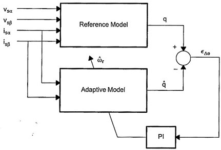
Two sets of equations for reactive power of motor are obtained in the reference and adaptive models. Reference model does not contain any rotor speed, whereas estimated rotor speed based on reactive power calculated from reference model is required for adaptive model. The reactive power equations can be obtained from both models for continuous and discrete times, which are given in the following. The complex number is defined for stator voltage and currents in the steady reference frame:
The back EMF of induction motor for continuous time is calculated in the reference model as follows:
The reactive motor power can be calculated from the multiplying stator current and back EMF:
where and are leakage coefficients. Then, the reactive power is ressed as follows:
The back EMF of induction motor for continuous time is calculated in the adaptive model as follows:
where rotor time constant; and can be calculated as follows:
After calculating the back EMF, , the reactive power is calculated as follows:
The PI controller continues to adjust calculated rotor speed, , until the reactive power from the adaptive model, , and the reference model, , are equal to each other. Rotor speed signal, , is the error for reactive power. This error can be calculated as follows:
Differential equations must be converted into required forms. The equations in reference and adaptive models can be expressed as in discrete forms. From Eq. (6), the following equation is obtained:
Eq. (14) can be simplified as follows:
where is sampling period.
According to Eq. (12):
In Eq. (16), and can be calculated as follows, respectively:
When and can be solved using by trapezoidal integration method, the following equations are obtained:
3.1. Reference model
If Eq. (15) is divided by , the unit time expression will be as the following:
Rearranging Eq. (21) gives:
where , is base voltage and base current.
3.2. Adaptive model
where , , and base electrical speed. Similarly, Eq. (19) and Eq. (20) are divided by base current , and then the following equations are obtained:
where , , , , .
After calculating per unit ve from Eq. (25) and Eq. (26), per unit back EMF can be obtained from Eq. (23) and Eq. (24). In the adaptive model, per unit reactive power can be calculated from Eq. (16). It is seen that is neglected because it is so small.
4. Simulation
The proposed method was verified by SIMULINK, MATLAB. In Table 1, variables and functions of MRAS module used in the simulation is given.
Table 1The variables and functions of MRAS module
Variable | Definition | Program variables | |
Inputs of reference model | Constant alfa-axis stator current (pu) | ualfa_mras | |
Constant beta-axis stator voltage (pu) | ubeta_mras | ||
Constant alfa-axis stator current (pu) | ialfa_mras | ||
Constant beta-axis stator current (pu) | ibeta_mras | ||
Output | Estimated rotor speed (pu) | wr_hat_mras | |
Init/Configa | |||
Base speed (rev/min) | Base speed = 120*base frequency / no_poles | ||
Other parameters | Ealfa | ||
Ebeta | |||
imalfa_high, imalfa_low | |||
imbeta_high, imbeta_low | |||
Q | |||
q_hat | |||
Error | |||
a: These constants are calculated by using machine parameters (, , , ), base units (, , ) and sampling period (). | |||
The drive is operated in speed mode with speed feedback is taken from the MRAS speed estimator. In all simulations, the estimated speed was used for the vector controller, while the actual speed was given for comparison.
Rotor flux reference (i.e. stator axis current reference) is ramped from 0 to 0.01 s to twice the rated value. In order to obtain a forced excitation, it is kept at twice the rated value from 0.01 to 0.05 s. Next, it is reduced from twice rated value to the rated value in a linear fashion from 0.05 to 0.06 s and it is kept constant for the rest of the simulation period. First of all, speed command is applied at 0.4 (pu) as it is constant. Starting is performed in 0.05 s as planned (Fig 7). It is seen that motor can be applied with the constant moment drive. The drive profile is decreased to its half after 1 s. It is seen that motor gives a constant moment in that case as well. In this study, the objective is to obtain that motor gives constant moment at zero speed.
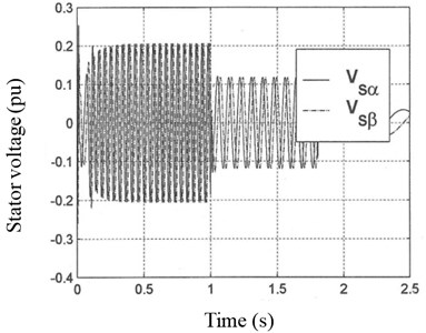
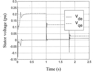
In Fig. 2, stator voltage at stationary reference frame and stator voltage at rotating rotor flux reference frame are given, respectively.
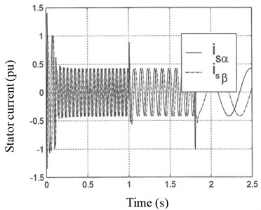
In Fig. 3, stator current at stationary stator reference frame and stator current ate rotating rotor flux reference frame are presented, respectively.
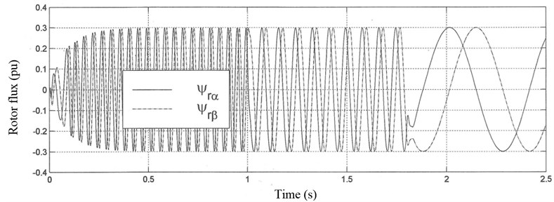
In Fig. 4, rotor fluxes at stationary stator reference frame are given.
Fig. 2a) Stator voltage at stationary stator reference frame and b) stator voltage at rotating rotor flux reference frame
a)
b)
Fig. 3a) Stator current at stationary stator reference frame and b) stator current at rotating rotor flux reference frame
a)
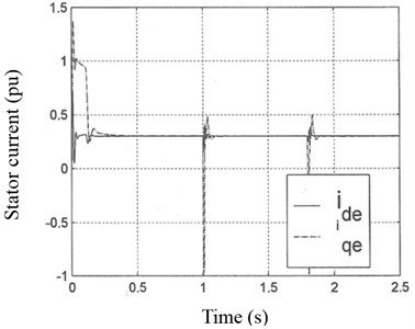
b)
Fig. 4Rotor fluxes at stationary stator reference frame
In Fig. 5, -axis rotor flux at rotating rotor flux reference frame is given. As seen in Fig. 5, mathematical model by MRAS provides that -axis rotor flux is keept constant at zero, as predicted. The rotor flux can be calculated accordingly.
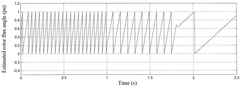
In Fig. 6, estimated rotor flux angle is given.
Fig. 5q-axis rotor flux at rotating rotor flux at rotating rotor flux reference frame
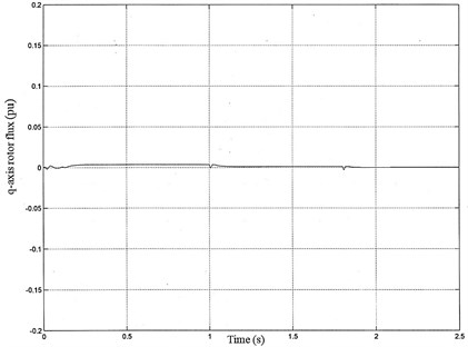
Fig. 6Estimated rotor flux angle
In Fig. 7 desired (real) rotor speed (pu) and induction motor torque (pu) are given. As seen from Fig. 7, motor continues to produce constant moment as load requires at zero speed region.
It can be seen from Fig. 7 that the rotor speed and moment control are fully decoupled. Acceleration takes place with the maximum allowed value of the motor torque. Actual motor phase current tracks the reference very well. Consequently, torque response closely follows torque reference and a small deviation appears only at the middle and end of the transient.
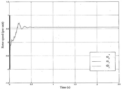
In Fig. 8 the real, estimated and reference motor speed are given. The mathematical model equalizes the estimated rotor speed taking the reference speed by a PI controller to obtain an error small as possible. The estimated rotor speed is equalized in 95 s.
As seen in Fig. 8, the estimated speed was in accordance with the real speed and reference rotor speed, therefore, the sensorless vector control was found to be working very effectively in all regions, including low speed and 0 rpm.
Since a sensorless vector control system is much more affected by the stator resistance error in a lower speed region, the proposed method clearly improved the low speed performance of the sensorless vector control system. As such, the proposed method was extremely robust to a variation in the mutual inductance.
For heavy duty motors, it is unavoidable that the stator resistance will change with temperature. Resistance change leads to inaccuracies in the rotor flux based estimation. Another limitation is related to the rotor flux based estimator. Its reference model contains a pure integrator, which brings drift in the rotor flux calculation. Another problem is that the setting the initial conditions for the integrator. Therefore, rotor flux based scheme has limitations in daily applications [18]. In this study, the proposed algorithm for the MRAS based technique may help to eliminate all those shortcomings. Especially, the noise due to lower speeds of induction motors widely overcome by the proposed method (Fig. 8). Besides noise reduction, less torque ripple may be considered as another advantage. As seen in Fig. 8, the system completely stabilizes and the estimated speed converges to the actual speed. In addition, application of this method for sensorless speed control may require less maintenance cost.
Fig. 7a) Desired rotor speed and b) desired moment of induction motor
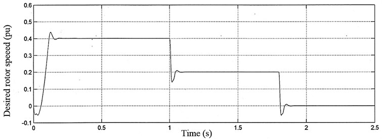
a)
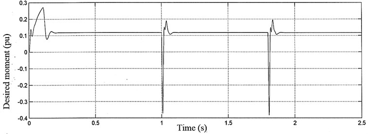
b)
Fig. 8Rotor speed waveform of sensorless control; ωr: real rotor speed, ω^r: estimated rotor speed, ωr*: reference rotor speed
5. Conclusions
This study deals with MRAS-based sensorless vector control of a three-phase induction machine, utilizing an indirect rotor flux oriented controller and current control in the stationary reference frame. The speed feedback signal is the estimated one obtained from MRAS-based speed estimator.The attainable performance are examined by simulation and compared. Rotor flux and torque control are fully decoupled, enabling the fastest possible accelarations and decelerations with the given torque limit. Results suggest that same technique may be extended to multi-phase multi-motor drives.
A rotor speed estimation method using MRAS was proposed to improve the performance of a sensorless vector controller. In the proposed method, the stator current is used as the state variable for estimating the speed. In conventional MRAS methods, the difference between state variables obtained by reference model and adjustable one has the unclear relationship with the speed estimation error. Yet in the proposed method the stator current error is represented as a function of the first degree for the error value in the speed estimation. In addition, the proposed method is robust to variations in the stator resistance. In particular, the proposed method is extremely robust to variations in the mutual inductance. As a result, the proposed method can produce an excellent speed estimation performance in a low speed region and at zero-speed. However, the rotor time constant uncertainty still remains as a problem.
The robustness of the proposed method as regards parameter variations was compared with that of conventional MRAS methods. In addition, the superiority of the proposed method was verified by simulation in a low speed region and at zero-speed. This study is a part of a simulation that is going to be performed for a practical application by Texas Instrument based high-performance DSP. As generally known that there is no need to install encoder or resolver to the shaft of induction motors for speed feedback in sensorless speed control. The work that is supposed to be done by an encoder or a resolver would be performed by the adaptive model in MRAS (Fig. 1). Thus, any external noise that may come from the encoder or resolver to the control block is eliminated. As shown in Fig. 7, induction motor produced smooth torque as desirable at lower speeds, especially at zero speed with this powerful flux predicted algorithm by using MRAS method.
With this method, the active and reactive components of apparent current of stator in induction motor produce moment (Fig. 7) and current (Fig. 4), respectively, as long as -axis rotor flux at zero speed or small errors around zero speed is realized as shown in Fig. 5. Therefore, the induction motor is controlled by vector control method similar to a separately excited direct current motor which can be controlled easily in industry.
In this study with the proposed sensorless speed vector control method, IGBT (Insulated Gate Bipolar Transistor) at the inverter stage of induction motor was simulated triggering by the SVM. This method is a digital method. As seen in Fig. 2(a) and Fig. 3(a), motor phases were obtained waves for voltage and current with smaller total harmonic distortion (THD) compared to classical Pulse Width Modulation (PWM). As shown in Fig. 1, speed and moment control without external noise (Fig. 7(a) and (b)) were achieved by eliminating internal time harmonics in motor phases as working perfectly together with SVM. This means eliminating external torque disturbance at the motor shaft.
As seen in Fig. 8, is the estimated speed by using motor equations in adaptive model based on MRAS. A small but continuous error is seen in Fig. 5 in -axis rotor flux. This error was reduced to a minimum by a PI controller (Fig. 1). The error was reduced by each calculation. Then, was calculated accordingly as real rotor speed, (Fig. 7(a)). Based on this real rotor speed, the rotor flux angle (Fig. 6) and the on time angle of IGBTs in inverter were calculated. It has been seen that induction motors perform very well with the proposed method as variable speed controller at low speed and at zero-speed. In addition, the proposed method controls induction motor without feedback speed sensor which can be used in the electrical car at the constant power region over 1.5 times of nominal speed without saturation by reducing flux producing current component of apparent stator current.
References
-
Khan M. R., Iqbal A., Ahmad M. MRAS-based sensorless control of a vector controlled five-phase induction motor drive. Electric Power Systems Research, Vol. 78, 2008, p. 1311-1321.
-
Parsa L., Toliyat H. Sensorless direct torque control of five-phase interior permanent magnet motor drives. IEEE Industry Applications Conference, 39th IAS Annual Meeting, Vol. 2, 2004, p. 992-999.
-
Holtz J. Sensorless control of induction machines-with or without signal injection? IEEE Trans. Ind. Electron., Vol. 53, Issue 1, 2006, p. 7-30.
-
Holtz J. Sensorless control of induction motors. Proc. IEEE, Vol. 90, Issue 8, 2002, p. 1358-1394.
-
Elbuluk M. E., Tong L., Husain I. Neural entwork based model reference adaptive systems for high performance motor drives and motion controls. IEEE Trans. Ind. Applic., Vol. 38, Issue 3, 2002, p. 879-886.
-
Rao P., Nakka J., Shekar R. Sensorless vector control of induction machine using MRAS techniques. International Conference on Circuits, Power and Computing Technologies (ICCPCT), Nagercoil, India, 2013, p. 167-175.
-
Park C., Kwon W. Simple and robust speed sensorless vector control of induction motor using stator current based MRAC. Electr. Power Syst. Res., Vol. 71, 2004, p. 257-266.
-
Profumo F., Griva G., Pastrorelli M., Moreira J. C. Universal field oriented controller based on airgap flux sensing via third harmonic stator voltage. IEEE Trans. Ind. Appl., Vol. 30, Issue 2, 1994, p. 448-455.
-
Kim Y. R., Sul S. K., Park M. H. Speed sensorless vector control of an induction motor using an extended Kalman filter. IEEE Trans. Ind. Appl., Vol. 30, Issue 5, 1994, p. 1225-1233.
-
Guzinski J., Abu-Rub H. Speed sensorless induction motor drive with predictive current controller. IEEE Trans. Ind. Electron., Vol. 60, Issue 2, 2013, p. 699-709.
-
Gao Z., Colby R. S., Turner L., Leprettre B. Filter design for estimating parameters of induction motors with time-varying loads. IEEE Trans. Ind. Electron., Vol. 58, Issue 5, 2011, p. 1518-1529.
-
Boglietti A., Cavagnino A., Lazzari M. Computational algorithms for induction-motor equivalent circuit parameter determination. Part I: Resistances and leakage reactances. IEEE Trans. Ind. Electron., Vol. 58, Issue 9, 2011, p. 3723-3733.
-
Lin W. M., Su T. J., Wu R. C. Parameter identification of induction machine with a starting no-load low-voltage test. IEEE Trans. Ind. Electron., Vol. 59, Issue 1, 2012, p. 352-360.
-
Marwali M. N., Keyhani A. A comparative study of rotor flux based MRAS and back EMF based MRAS speed estimators for speed sensorless vector control of induction machines. Proceedings of the IEEE-IAS Annual Metting, 1997, p. 160-166.
-
Blasco-Gimenez R., Asher G. M., Sumner M., Bradley K. J. Dynamic performance limitations of MRAS based sensorless induction motor drives. Part I: Stability analysis for the closed loop drive. IEE Proc. Electr. Power Appl., Vol. 143, Issue 2, 1996, p. 113-122.
-
Chao K. H., Liaw C. M. Speed sensorless control performance improvement of induction motor drive using uncertainty cancellatio. IEE Proc. Electr. Power Appl., Vol. 147, Issue 4, 2000, p. 251-262.
-
Vas P. Sensorless vector and direct torque control. Oxford University Press, 1998.
-
Purushottama R., Jayaram N., Shekar R. Sensorless vector control of induction machine using MRAS techniques. International Conference on Circuits, Power and Computing Technologies, Nagercoil, India, 2013, p. 167-175.
About this article
