Abstract
Diesel engines are the most important equipments in the marine propulsion system. Due to offshore working condition, it is essential to establish remote network to monitor the health status of the diesel engines. Unfortunately, very limited work has been done for remote condition monitoring and fault diagnosis (CMFD) of marine diesel engines. To address this issue, we present a novel remote CMFD system to detect engine combustion fault, which appropriately introduces the compressive sensing technique into the remote data transmission. The instantaneous angular speed (IAS) signal of the engine is transferred remotely from the ship to shoreside data center. Combustion fault detection is achieved by time-frequency spectrum analysis on the decompressed IAS data. The key advantage of our proposed remote CMFD system is that the IAS data has been sampled in a low-speed manner by compressive sensing, thus greatly reducing the computational requirements in the data transmission. We have established our proposed remote CMFD system for a real dredger to demonstrate its efficiency in the engine combustion fault detection.
1. Introduction
Diesel engine has been served in more than 99 % of the marine propulsion systems [1]. The normal operation of the engine ensures the scheduled completion and safety of trips. However, due to harsh working environment the diesel engines are prone to damage [2]. Hence enhancing the engine reliability becomes a major challenge for the engineers.
Representative failure modes of the marine diesel engines are mainly the wear and fatigue of piston – cylinder liner, cylinder burning, abnormal valve clearance and valve leakage, bearing pad burning and so forth [3]. Any faults on these engine components will significantly influence the combustion condition in the cylinder. Due to the complex engine structure, it is hard to directly determine whether a fault occurs in the mentioned components; however, one can detect the combustion condition to access the health status of the engine. By doing so, it can realize non-constructive detection of the engines. A practical way to detect engine combustion fault for diesel is the instantaneous angular speed (IAS) method owning to simple and reliable installation of the speed encoder [4]. A large amount of information is contained in the IAS signal while given the special working environment of the ships professional knowledge is appreciably required in the analysis of the IAS. It is not realistic to arrange experts in every ship; for alternative, a remote condition monitoring and fault diagnosis (CMFD) system may perfectly solve this issue. The key advantage of remote CMFD is that only one expert is employed in the shoreside data center to provide fault detection service for a group of ships. Moreover, remote CMFD can provide systematic and comprehensive fault diagnosis for ships. Hence, the particular features of remote CMFD system have conduced a lot of scientists in the very last years to establish such systems in practice. Song et al. [5] designed a remote CMFD system for a ship engine room. The work efficiency of the engine room has been improved by the application of the designed system. Guo et al. [6] developed a remote CMFD for gas turbines in warships. In our previous work [7, 8] we have established a remote CMFD system for marine diesel engines in practice. However, in the existing remote CMFD systems the data transmission efficiency limits their performance in practice. This is because the Nyquist-Shannon sampling theorem has dominated the data transmission procedure in the past decades while the inherit characteristics of sampling theorem have become a major bottleneck to the further development of information processing [9, 10]. On the one hand, Nyquist-Shannon sampling theorem belongs to high speed sampling. It will generate a large amount of data sets in the data acquisition, leading to high cost but low efficacy in data collection [9]. On the other hand, in the data storage and transmission one need to process a large amount of data sets when using Nyquist–Shannon sampling theorem, which causes time-consumption calculation and serious resource waste; moreover, the risk of signal decompression and reconstruction will increase greatly if massive data being processing [9]. This is why a new signal acquisition technology, the Compressive Sensing (CS), has come into birth to enhance the efficiency of data acquisition, storage and transmission. Different to Nyquist-Shannon, CS adopts low-speed sampling to achieve data acquisition and compression at the same time. This advantage makes CS much simpler than Nyquist-Shannon in expressing the original signal. Good approximation of the original signal can be obtained by performing a small number of generalized measurements [10]. The data sampling points of CS are much less than Nyquist-Shannon. As a result, the Compressive Sensing technology has attracted much attentions in information theory, signal/image processing, medical imaging, pattern recognition, geological exploration, optical/radar imaging, wireless communications, and so forth [10], and is awarded as top 10 scientific and technological progress in 2007 by United States. It is promising to incorporate CS into the remote CMFD system to provide a practical solution on the remote data transmission. However, very limited work has been done to address this issue, neither the development of CS in remote CMFD for marine diesel engines.
To develop an efficient data storage and transmission technique in remote CMFD system for marine diesel engines, this work proposed a novel solution by incorporating the Compressive Sensing into the system. The application of the system in a real dredger has shown good performance of the new remote system.
2. Brief introduction of compressive sensing (CS)
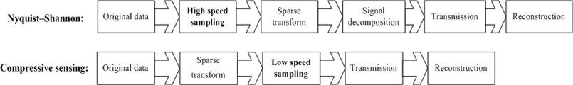
Compressive sensing (CS) is a new collection of sampling and signal reconstruction technology. CS can well approximate an unknown signal using much less number of measurements than Nyquist-Shannon sampling [9]. For remote data transmission, it means that CS can be used to reduce the storage requirement and computation consumption. Fig. 1 compares the signal transmission principles of CS and Nyquist–Shannon. It can be seen in the figure that the procedure of CS based data transmission is much simpler than the Nyquist-Shannon method. Hence computational efficiency of the CS method is achieved by reducing the storage requirement and computation consumption.
Fig. 1Data transmission comparison of CS and Nyquist-Shannon
CS mainly consists of the sparse decomposition, projection measurement and reconstruction algorithm. Let us briefly introduce the theory of compressive sensing. The details of CS theory can refer to [9-12].
(1) Sparse decomposition. Consider that the signal of interest is a vector and there is an orthonormal basis for :
where, is the inner product of , i.e. ; . If and only if there are () nonzero coefficients for in the orthonormal basis , becomes the sparse basis for .
(2) Projection measurement. The CS trick aims to project into a sensing basis to obtain the linear estimation of , i.e.:
Combine (1) and (2) we derive:
One can note from (3) that CS reduces into an estimation with size ().
(3) Reconstruction. In order to accurately recover from , the matrix should meet the Restricted Isometry Property (RIP) [10]:
where, is an arbitrary vector with strict -sparse; is a small positive constant.
Hence, (4) requests a suitable design of and . Generally, the orthonormal basis adopts discrete cosine basis, wavelet basis, or FFT basis, etc. The sensing basis can choose random matrix [13, 14]. Then, the -minimization [10] could be used to reconstruct from .
A numerical simulation is carried out to quantitatively highlight the advantage of CS in the data sampling against Nyquist-Shannon method.
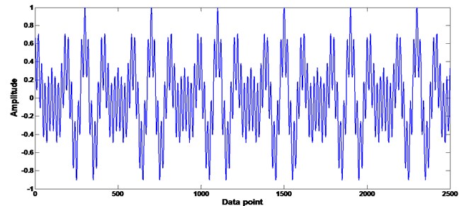
Given the following source signal:
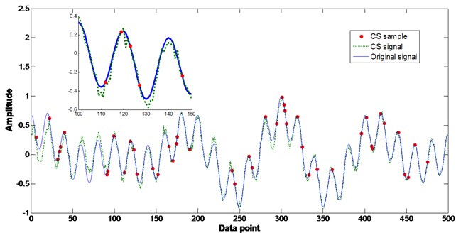
Eq. (5) presents a typical healthy vibration signal of the piston-cylinder pair in a diesel engine [3]. According to Nyquist-Shannon sampling theorem, choose 20 kHz sampling frequency, after 1/8 second we get 2500 data points, as shown in Fig. 2(a). However, only 250 data points are sufficient for CS to describe the original signal (shown in Fig. 2(b), where the orthonormal basis adopted discrete cosine basis). One can be noticed in Fig. 2 that CS could perform very small sampling points to accurately reconstruct the original signal. Compared with Nyquist-Shannon, the data storage can be numerous relieved by CS in a low-speed sampling manner. Since CS significantly reduces the computational complexity in the signal storage and remote transmission, a promising application of CS can be expected for the remote CMFD system of marine propulsion.
Herein, we have also discussed in details about the sparse issue and different sampling distributions of the measurements in CS processing. Firstly we discussed how sparse can be the measurements in CS case. According to Eqs. (1)-(4) one can note that the sparse of the measurement is mainly determined by parameter . Hence in the simulation different values were selected to inspect the influence of sparse on the CS performance. Fig. 3 shows the simulation results with different values. It can be seen in the figure that when is as small as 10, the CS failed to reconstruct the original signal ; however, with the increase of the sparse the CS has improved its performance on the recovery of the original signal from a small portion of sample points. In order to quantitatively discuss the relationship between the sparse degree and the CS performance, the Pearson correlation coefficient [15] was adopted to investigate the correlation of the original signal x and the recovery :
where, is the total sample point, is the average of , and is the average of .
Fig. 2Comparison of CS and Nyquist–Shannon in signal sampling: a) Nyquist–Shannon, b) CS
a)
b)
Table 1 lists the Pearson correlation coefficient with different values. It can be seen in the table that when the sparse of the measurement is very low, the correlation coefficient between the original signal and the recovery signal is very small; specifically, when 10 (the sparse degree is 1/250), there is no correlation between the original signal and the recovery signal. If increase the sparse of the measurement, the CS can recover the original signal accurately and when 500 (the sparse degree is 1/5) the correlation coefficient 0.9945. The calculation results in Table 1 indicate that a large value will generate precise recovery signal while its computation amount and storage request may increase. In engineering practice, the error tolerance should be less than 5 % [3]. When 250 (the sparse degree is 1/10) the correlation coefficient 0.9515, which may meet the engineering practice requirement with very small number of data points.
Table 1Pearson correlation coefficient r with different K values
values | 10 | 50 | 100 | 150 | 200 | 250 | 500 |
Pearson correlation coefficient | 0.002 | 0.5274 | 0.7706 | 0.9391 | 0.9403 | 0.9515 | 0.9945 |
Fig. 3Influence of sparse on the CS performance with different K values
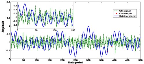
a)10
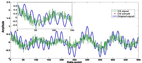
b)50
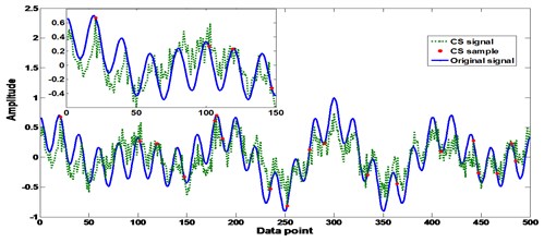
c)100
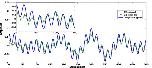
d)150
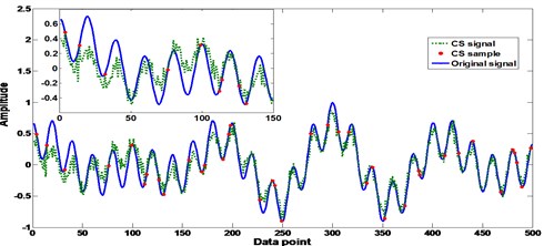
e)200
The different sampling distributions of the measurements in CS processing have also been investigated in this work. Three typical signal types that usually appear in the machine vibrations have been used to carry out the simulation. These signal types include the pulse signal, sawtooth signal, and square signal. In CS cases, the option of orthonormal basis may significantly influence the signal reconstruction. Suitable orthonormal basis may generate satisfactory CS recovery performance. Hence, the investigation of the discrete cosine basis, wavelet basis, and FFT basis has been implemented in the simulation to evaluate the CS performance. Different values have been used to inspect the influence of sparse degree on the CS performance. The analysis results are given in Tables 2-5. In the numerical analysis, the Daubechies wavelet basis was adopted.
Table 2Pearson correlation coefficient r with different K values using different ψ: pulse signal case
values | |||||||
10 | 50 | 100 | 150 | 200 | 250 | 500 | |
FFT basis | 0.004 | 0.4975 | 0.6542 | 0.8623 | 0.9218 | 0.9636 | 0.9915 |
Daubechies wavelet basis | 0.001 | 0.4663 | 0.5899 | 0.8144 | 0.9203 | 0.9611 | 0.9934 |
Discrete cosine basis | 0 | 0.3891 | 0.5674 | 0.7258 | 0.8462 | 0.8619 | 0.8922 |
Table 3Pearson correlation coefficient r with different K values using different ψ: sawtooth signal case
values | |||||||
10 | 50 | 100 | 150 | 200 | 250 | 500 | |
FFT basis | 0 | 0.1469 | 0.2477 | 0.3832 | 0.4601 | 0.4761 | 0.5615 |
Daubechies wavelet basis | 0 | 0.3026 | 0.4208 | 0.6901 | 0.7852 | 0.8603 | 0.9675 |
Discrete cosine basis | 0 | 0.2467 | 0.2987 | 0.3486 | 0.3985 | 0.4043 | 0.6603 |
Table 4Pearson correlation coefficient r with different K values using different ψ: square signal case
values | |||||||
10 | 50 | 100 | 150 | 200 | 250 | 500 | |
FFT basis | 0 | 0.2711 | 0.3976 | 0.4298 | 0.5607 | 0.6263 | 0.8027 |
Daubechies wavelet basis | 0 | 0.3751 | 0.5846 | 0.6942 | 0.7924 | 0.8571 | 0.9053 |
Discrete cosine basis | 0 | 0.4068 | 0.6148 | 0.7525 | 0.8308 | 0.9073 | 0.9507 |
Table 5Pearson correlation coefficient r with different K values using different ψ: signal in (5)
values | |||||||
10 | 50 | 100 | 150 | 200 | 250 | 500 | |
FFT basis | 0 | 0.2373 | 0.4254 | 0.4727 | 0.6585 | 0.6439 | 0.7562 |
Daubechies wavelet basis | 0 | 0.3456 | 0.4981 | 0.7254 | 0.7839 | 0.8265 | 0.8731 |
Discrete cosine basis | 0.002 | 0.5274 | 0.7706 | 0.9391 | 0.9403 | 0.9515 | 0.9945 |
It can be seen in Table 2 that the Daubechies wavelet basis and FFT basis produced good performance for pulse signal; in Table 3, the suitable was Daubechies wavelet basis and in Tables 4 and 5 the discrete cosine basis outperformed the other two . Hence, the investigation results demonstrate that different orthonormal basis may be effective for different sampling distributions of the measurements in the CS processing; for this specific case of diesel engine signal, the discrete cosine basis and the Daubechies wavelet basis were more suitable than the FFT basis.
3. Design of the CS based remote CMFD system
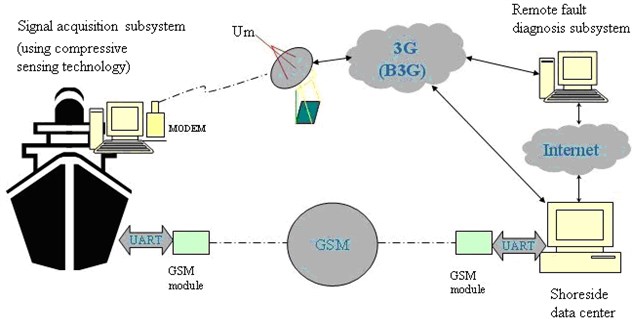
To ensure the ship safety, a novel remote CMFD system is developed where the CS has been incorporated to enhance the data remote transmission efficiency. Fig. 4 shows the framework of the remote CMFD system.
The system consists of an on-board signal acquisition subsystem, a shoreside remote fault diagnosis subsystem and a data centre. The communication between the signal acquisition subsystem and the remote fault diagnosis subsystem adopted the 3G/B3G remote transmission technique, and the Global System for Mobile Communications (GSM) technique was employed for the remote connection of data centre and the ship.
Fig. 4The overall design of the remote CMFD system
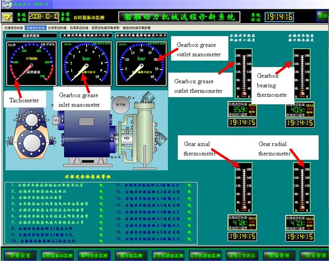
The signal acquisition subsystem is used to collect the diesel engine operation parameters. Fig. 5 shows the detailed structure of the signal acquisition subsystem. The fieldbus technology was used to construct the subsystem. The monitoring objects include the diesel engines and their hydraulic systems. Various sensors were installed on the monitoring objects to record their operation parameters, including the temperatures, pressures, rotation speeds, vibrations, etc. Then the configuration software was used to display and store the recorded data. Fig. 6 shows, for instance, the software interface for the monitoring and display of an engine gearbox. The engineers can receive all the monitoring machine operation parameters in the engine rooms. Moreover, these recorded signals can be transmitted to the shoreside fault diagnosis subsystem via 3G/B3G networks, where the CS could be used to compress the data in the ship side and reconstruct the data in the shoreside to enhance the data transmission efficiency.
Fig. 5The detailed structure of the signal acquisition subsystem
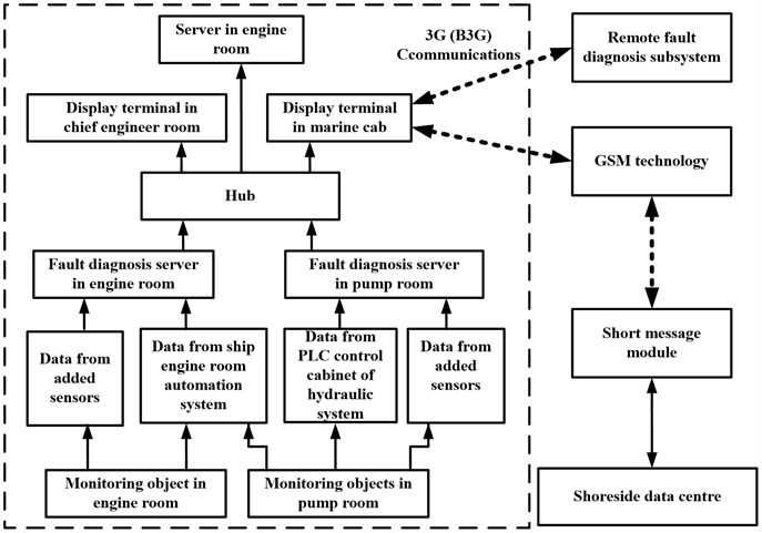
Fig. 6The detailed structure of the signal acquisition subsystem
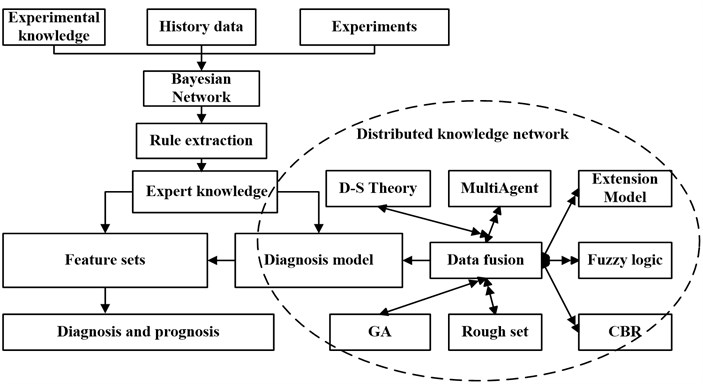
The remote fault diagnosis subsystem has integrated a series of signal processing functions based on the MATLAB software to provide signal processing services. These services include the vibration analysis for vibration signals in time domain or/and frequency domain, image processing for ferrography, and threshold setting for temperatures and pressures, etc. Important features could be extracted in signal processing services for the detection of incipient machine failures. Taking advantages of artificial intelligence, the expert system was employed to mine the hidden rules in the extracted features for the fault diagnosis and prognosis in the remote fault diagnosis subsystem. Fig. 7 shows the expert system framework of intelligent diagnosis and prognosis for marine diesel engines.
The shoreside data center makes decisions on the signal analysis results and communicates with the ship engineers via GSM.
Fig. 7The expert system of intelligent diagnosis and prognosis for marine diesel engines
4. Application in marine diesel engine combustion fault detection
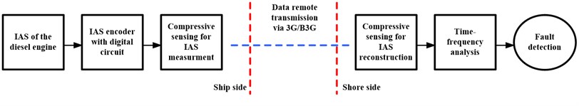
In this work we have investigated the CS-based data transmission performance in the proposed remote CMFD system for marine diesel engine combustion fault diagnosis in practice. A series of experiments have been implemented to detect the main engine combustion fault in a real dredger named “Hangjun 20”. The type of the diesel engine is Sweden Volvo Penta TAMD165C. The instantaneous angular speed (IAS) method [2, 16] is employed to detect the engine combustion faults. The engine IAS signal is transferred remotely from the ship to shore side using the CS technique. Fig. 8 shows the IAS signal acquisition device in “Hangjun 20” dredger and Fig. 9 shows the CS-based IAS signal remote transmission scheme.
Fig. 8The IAS signal acquisition device in “Hangjun 20” dredger
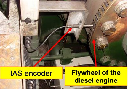
Fig. 9The CS-based IAS signal remote transmission scheme
When faults occur in the engine combustion process, the IAS signal may be distorted due to the reduction of the engine power torque [2]. Thus, through the time-frequency spectrum analysis useful features could be extracted from the IAS signal to detect the combustion faults.
Consider that the rotational speed of a four-stroke diesel engine is rev/min, the operating time per engine cycle is 120 s, and hence the basic operating frequency of the engine is:
The ignition frequency of the engine is:
where, is the cylinder number.
In the experimental tests, the engine was operated in normal and 3rd cylinder oil leakage conditions for 30 minutes, respectively. The engine speed was 1500 rev/min. The cylinder number was 6. Hence the basic operation frequency was 12.5 Hz, and the firing frequency was 75 Hz. In order to detect the engine combustion fault, the CS was firstly adopted to transfer the IAS data from the ship to the shoreside fault diagnosis subsystem. Then the IAS signal was recovered in the shore side by -minimization [10] algorithm. Fig. 10 shows the IAS reconstruction results. Compared with the traditional data transmission technique, the CS only costs as small as 1/4 of the Nyquist–Shannon data amount to precisely present the original IAS signal with a mean square error (MSE) of 5.01310-5. This means that by the compressive sensing the data usage efficiency has been increased by at least 3/4 against the traditional Nyquist–Shannon method and the calculation consumption in the data remote transmission has hence been significantly improved. Herein, we have also discussed the sparse issue in CS processing. Table 6 compares the CS reconstruction performance of different orthonormal basis under different sparse degrees in the CS processing.
Fig. 10IAS reconstruction by CS after the remote data transmission
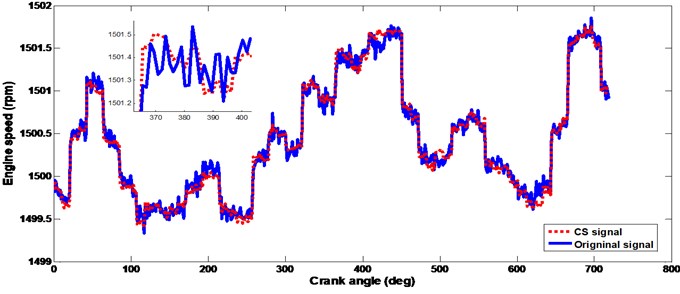
Table 6Pearson correlation coefficient r with different K values using different ψ: IAS signal
Sparse degree | |||||||
1/100 | 1/20 | 1/10 | 1/6 | 1/5 | 1/4 | 1/2 | |
FFT basis | 0 | 0.1893 | 0.2359 | 0.3782 | 0.4072 | 0.5748 | 0.6046 |
Daubechies wavelet basis | 0 | 0.2651 | 0.4755 | 0.6434 | 0.7151 | 0.8395 | 0.9651 |
Discrete cosine basis | 0 | 0.2767 | 0.4732 | 0.6956 | 0.8746 | 0.9545 | 0.9702 |
It can be seen in Table 6 that the IAS recovery using the FFT basis was not accepted; the highest correlation coefficient was 0.6046 for FFT basis. Hence, the FFT basis is not suitable for the case of IAS processing. This result agrees well with the simulation result in Table 5. The reason for the inefficiency of the FFT basis in the IAS signal reconstruction may be the occurrence of frequency mixing in the IAS frequency band. One can note that both the Daubechies wavelet basis and discrete cosine basis are effective for the IAS reconstruction; however, when the sparse degree is 1/4 the discrete cosine basis is superior to the Daubechies wavelet basis. Hence, in this work we adopted the discrete cosine basis with 1/4 sparse degree in the IAS data remote transmission processing. Fig. 11 shows the reconstruction IAS signals under normal and faulty conditions. The bispectrum [17] was employed as a time-frequency analysis tool in the MATLAB software to analyze the reconstruction IAS signals. Fig. 12 shows the fault diagnosis using time-frequency spectrum analysis.
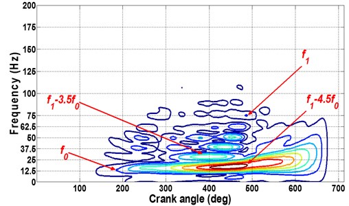
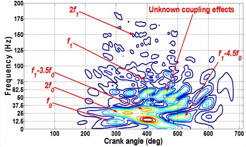
Theoretically, when faults occur, large impact energy will emerge at the basic operation frequency [2, 16, 17]. One can observe in Fig. 12 that in normal condition the energy crests are mainly concentrated at (3.5) and (4.5); however, when failure occurs the energy crest located at the fault frequency and its harmonics. Moreover, cyclical impacts arise at unknown frequency caused by complex coupling movements of the engine components. These observations agree well with the theoretic analysis and they could indicate the appearance of the engine. In addition, it can be seen in Fig. 12(b) that the largest energy crest arises around 400 deg in the -axis when the 3rd cylinder experiences its exhaust stroke. Hence, it can infer that the failure happened in the 3rd cylinder.
Fig. 11Reconstruction IAS signals after CS data remote transmission
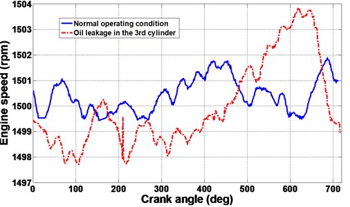
Fig. 12Fault recognition: a) normal and b) oil leakage
a) Normal condition
b) Oil leakage in 3rd cylinder
5. Conclusions
Efficient data remote transmission may greatly improve the performance of the remote CMFD system. Compressive sensing (CS) can break the bottleneck of the Nyquist-Shannon sampling theorem to provide efficient data remote transmission. However, little work has been done to address this issue. This work appropriately incorporates the CS into the remote CMFD system to provide practical solution for the fault diagnosis of marine diesel engines. This novel remote system has been established in real ships and has been proven to be promising for the remote transmission of engine operation signals. Experimental tests have been carried out in this work to demonstrate and evaluate the performance of the new system. The analysis results show that the computational efficiency is achieved by using the CS technology and the remote non-disassembly fault detection of marine engine combustion faults can be realized. Thus the new system has practice importance.
References
-
Lamaris V., Hountalas D. A general purpose diagnostic technique for marine diesel engines – application on the main propulsion and auxiliary diesel units of a marine vessel. Energy Conversion and Management, Vol. 51, Issue 4, 2010, p. 740-753.
-
Li Z., Yan X., Yuan C., Peng Z. Intelligent fault diagnosis method for marine diesel engines using instantaneous angular speed. Journal of Mechanical Science and Technology, Vol. 26, Issue 8, 2012, p. 2413-2423.
-
Li Z. Investigation on the dynamics modeling and condition monitoring of the propulsion system in large scale ships. Ph. D. thesis, Wuhan University of Technology, Wuhan, 2013, (in Chinese).
-
Charles P., Sinha J., Gu F., Ball A. Application of novel polar representation method for monitoring minor engine condition variations. Mechanical Systems and Signal Processing, Vol. 24, Issue 3, 2010, p. 841-843.
-
Song X., Ma A., Ma Q., Zhang Y. The design of remote fault diagnosis system in engine room. Applied Mechanics and Materials, Vol. 174, 2012, p. 1971-1976.
-
Guo W., Sun Y., Pu H. A remote fault diagnosis system for gas turbines in warships. J. Nav. Univ. Eng., Vol. 24, Issue 1, 2012, p. 73-76, (in Chinese).
-
Yan X., Zong C., Sheng C., Shang Q., Yu Y. A remote fault diagnosis system for marine diesel engines. J. Wuhan Univ. Technol., Vol. 32, 2010, p. 118-121, (in Chinese).
-
Yan X., Li Z., Yuan C., Guo Z., Tian Z., Sheng C. On-line condition monitoring and remote fault diagnosis for marine diesel engines using tribological information. Chemical Engineering Transactions, Vol. 33, Issue 1, 2013, p. 805-810.
-
Candes E., Romberg J., Tao T. Robust uncertainty principles: exact signal reconstruction from highly incomplete frequency information. IEEE Transactions on Information Theory, Vol. 52, Issue 2, 2006, p. 489-509.
-
Donoho D. Compressed sensing. IEEE Transactions on Information Theory, Vol. 52, Issue 4, 2006, p. 1289-1306.
-
Donoho D., Tsaig Y., Drori I. Sparse solution of underdetermined systems of linear equations by stagewise orthogonal matching pursuit. IEEE Transactions on Information Theory, Vol. 58, Issue 2, 2012, p. 1094-1121.
-
Baraniuk R. Compressive sensing. IEEE Signal Processing Magazine, Vol. 24, Issue 4, 2007, p. 118-121.
-
Candes E., Tao T. Decoding by linear programming. IEEE Transactions on Information Theory, Vol. 51, Issue 12, 2005, p. 4203-4215.
-
Candes E., Romberg J., Tao T. Stable signal recovery from incomplete and inaccurate measurements. Communications on Pure and Applied Mathematics, Vol. 59, Issue 8, 2006, p. 1207-1223.
-
Soper H., Young A., Cave B., Lee A., Pearson K. On the distribution of the correlation coefficient in small samples. Appendix II to the papers of “Student” and R. A. Fisher. A co-operative study. Biometrika, Vol. 11, 1917, p. 328-413.
-
Charles P., Sinha J., Gu F., Lidstone L., Ball A. Detecting the crankshaft torsional vibration of diesel engines for combustion related diagnosis. Journal of Sound and Vibration, Vol. 321, Issue 3-5, 2009, p. 1171-1185.
-
Zhang L., Mei J., Jia J., Qiao L., Zhou J. Feature extraction for accelerating vibration signal of a diesel engine based on order bispectrum estimation. Journal of Vibration and Shock, Vol. 32, Issue 1, 2013, p. 154-159.
About this article
This project is sponsored by the National Basic Research Program of China (973 Program) (No. 2014CB046303) and the Fundamental Research Funds for the Central Universities (2014QNA37).
