Abstract
In order to improve the reliability of changing tool for ATC (automatic tool changer), a horizontal tool changer of machining center is chosen as the example to study the dynamic characteristics in the condition of changing a heavy tool. This paper analyzes the structure and properties of the tool changer by simulation and experiment, and the space trajectory equations of the manipulator and tool are derived. The maximum force is calculated in the processing of changing tool. A virtual platform for the automatic tool changer is built to simulate and verify the dynamic performance of the tool changer; the simulation results show an obvious vibration in the process of changing tool, which increases the probability of failure for changing tool. Moreover, in order to find out the device's vibration reasons, a professional experiment platform is built to test the dynamic characteristics. Based on the testing results for a horizontal tool changer, it is known that the unstable vibration is mainly caused by the collision of the tool. Finally, an optimization method for the manipulator is proposed to reduce this vibration and improve the reliability of the tool changer. The final simulation and experiment results show that the optimized manipulator can grasp the heavy tool stably, and the vibration amplitude is significantly reduced in the process of changing tool.
1. Introduction
Automatic tool changer ATC, as an important component in the processing center, can reduce the non-cutting time, increase productivity and reduce production costs [1-4]. Currently, the speed and mass of changing tool for automatic tool changer need to be limited according to the actual situation. If the working conditions are beyond this limit, the accidents of tool falling will occur [5-6]. Most of the research about automatic tool changer device uses a virtual prototype technology to test and evaluate the quality and performance of changing tool [7-8]. In recent years, the automation tool changer plays an important role, and a variety of tool changers are developed and researched. The species also become diverse. But the changed tool is mostly light and medium-size and little research focus on the stability of the tool changer for heavy tool [8-11]. So it is not unclear whether the mechanical properties of the manipulator can meet the mechanical processing’s requirements when it changes a heavy tool. In this paper, the working principle of the tool changer is analyzed. Through the comparison of the theoretical calculations and simulation, the cyclical movement of tool changer is mastered. However, the testing technology and method are very few and not common [12-13]. So a dynamic characteristic testing system based on the virtual instrument was developed to study the ability of changing tool and dynamic characteristics of automatic tool changer. According to the structure and movement characteristics of automatic tool changer, a measuring method of changing tool and collision characteristic was proposed in the conditions of the dynamic loads. The sensors were installed, and the interfaces were designed by Labview. The testing data was processed and analyzed by Matlab. The actual testing results provided the important experimental data for the research on dynamic characteristics. The vibration from the process of changing tools seriously affects the stability. In order to analyze the causes of vibration, the vibration accelerations were tested in several locations. After analyzing the correlation between the output signals, the main vibration source was determined primarily near the manipulator. After comprehensively analyzing the manipulator’s displacement, it was determined that the vibration is produced by the collision of catching tool and inserting tool.
The tools of a machining center are loaded and unloaded by the automatic tool changer. And the tool falling and vibration faults often occur in the process of changing tool [14-15]. At present, the widely used manipulator of the hook knife type has a great advantage in the aspect of time and space, but there always has been an instable problem of clamping tool. Even if the size and shape of the original manipulator’s structure are optimized as well as possible, it is hard to meet need of the rapid changing tools for the machining center [16-17]. Thus it has an important significance to study the manipulator’s ability of clamping tool. And the reliability and stability are also seen as the important evaluation indexes [18]. According to the above problems, the old manipulator is improved by designing two-point locking on the base of the one-point locking, and the tools can be clamped more tightly. The output curve of the manipulator is obtained and analyzed. Through the simulation and experiments for the manipulator, the result proves that it increases obviously for the abilities of preventing tools falling, resisting the impact and ensuring tools stable.
In short, through the virtual simulation and experimental testing for the automatic tool changer, the acquired dynamic data is processed and analyzed, and then the causes of the vibration are found out. By an innovative method, the manipulator was optimized and improved, so that the reliability of changing tool was solved to some extent, and the speed and quality of changing tool can be improved. The paper is organized as follows, in Section 2, the structure and principles of the tool changer are analyzed and calculated. In Section 3, the virtual platform is built, and the initial dynamic characteristics for changing tool are obtained. Moreover, an experimental testing platform is built, and the cause of the vibration is found out. In Section 4, the manipulator is optimized and redesigned to improve the ability of clamping heavy tool. Section 5 gives some conclusions and make an overview for the future work.
2. Structure analysis
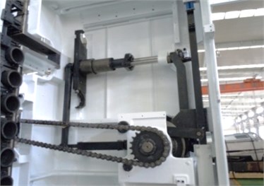
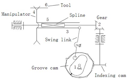
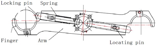
The structure diagram for automation tool changer is shown in Figure 1, which is consisted of the following components: Composite cam: composite cam is composed of indexing cam and groove cam, it belongs to a single input double output system; Swing link: the end of the swing link engages with groove cam, and the other end of the swing link is articulated with spline bushing; Indexing cam: the rollers in the indexing can engage with outside edge of the groove cam; Spline shaft: one end of the spline shaft is fixed with the manipulator, and the other end engages with the indexing cam. Manipulator: the manipulator plays a role in clamping, transporting and exchanging the tool.
Fig. 1Structure of automation tool changer
(a)
(b)
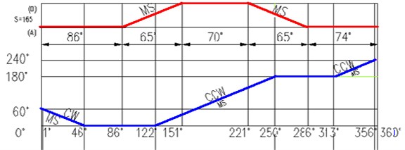
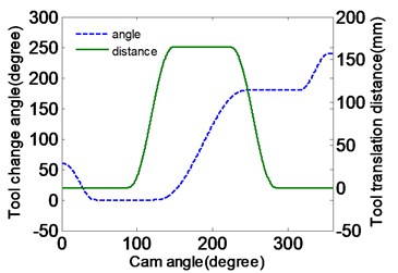
The actions of changing tool for automatic tool changer are shown in Fig. 2(a), where the curve located in the upper part is the horizontal distance of the manipulator for inserting tool, and the curve in the lower half is the rotational angle of the manipulator for changing tool. Firstly, the manipulator rotates 60 degrees in a counterclockwise direction for clamping tool and moves 167 mm in the horizontal direction for drawing tool. Then the manipulator gripes the tool to rotate 180 degrees in clockwise direction and move back 167 mm for inserting the tool. At last, the manipulator looses the tool and reverses 60 degrees back to its original position. Through the above operations, the needed tools in the spindle of the machine are replaced automatically by the tool changer.
The engaging curves of composite cam are improved by the modified sine curve; the original curves are connected at both ends of the cosine curve with a transition sine curve, which make the acceleration curve continues [19].
Fig. 2Motion law of the manipulator
(a)
(b)
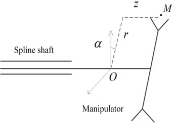
To calculate the space trajectory of the manipulator and tool, so the manipulator’s motion equation is established firstly. A cylindrical coordinate system is created as shown in Figure 2(b), by taking the spline shaft as -axis, the mechanical arm as the -axis and the initial angle of the mechanical arm in vertical line as , where the point is the position of holding tool for manipulator, and the coordinate origin is the initial position of the mechanical arm’s midpoint.
According to the coordinate system in Figure 2(b), the output equation of the manipulator can be written as follows:
where is the input angle of composite cam, is the mechanical arm's length, is the endpoint of the pendulum displacement, is the output angle of the composite cam. According to an improvement sine principle, the pendulum output equation is shown in Equation (2):
The output equation of the composite cam’s rotation angle is shown in Equation (3):
The time period of the manipulator for changing tool in Equation (2) and (3) is determined in Equation (4):
According to Formula (1-4), the trajectory of the manipulator can be obtained as Equation (5):
where the constant , and are the simplified representation.
In the process of the manipulator rotating, the tool’s forces will change constantly. If the tool cannot be grasped tightly, it will fall off, which is dangerous to the operator. So, it needs to be determined that when and where the biggest force occurs. The resultant force of the tool is expressed as the Formula (6):
where the symbol , and are the unit vectors in the rectangular coordinate system; is the arm length; is the output angle of the motor; is the quality of the tool; is the angle of the manipulator rotating; is the displacement of tool slotting; is the acceleration of gravity.
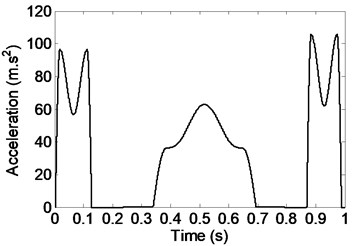
The tool-changing cycle 1 s, the arm 0.26 m. Without considering the acceleration of gravity, the inertial acceleration is expressed in Fig. 3(a). The total acceleration is bigger than the acceleration of gravity , so the inertial force is the main factor of influencing the tool’s stability. The manipulator rotates from 0.2 s to 0.3 s. In 0.5 s the peak is very meaningful. At this moment, the tool locates in the vertical position, and the centrifugal force and gravity is in a straight line. It can also be seen in Fig. 3(b) that the corrected output curve of the manipulator is smooth, thus the acceleration shock is avoided.
Fig. 3Inertial acceleration of the tool
(a)
(b)
3. Simulation and test for dynamic characteristics
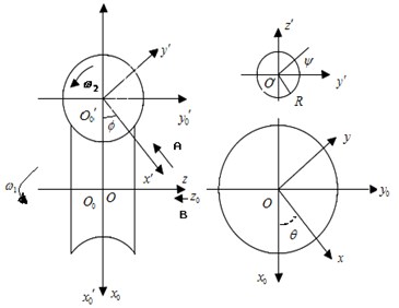
The above theoretical analysis shows the space trajectory and actions of changing tool for the manipulator. Now let’s build a virtual platform of the automatic tool changer device to simulate the moving processing. It is more complex to build the model of composite cam than others. This method is the secondary development by using high-level language of three-dimensional software. According to the engaging principle of the globoidal indexing cam and the indexing plate, the coordinate systems are built as Fig. 4(a). Among them, is the auxiliary fixed coordinate system connected with the rack of the indexing plate; is the fixed coordinate system connected with the rack of the composite cam; is the moving coordinate system connected with the composite cam; is the moving coordinate system connected with the indexing plate; and , are the angular velocities of the composite cam and the indexing plate; and are the corner of the composite cam and indexing plate; is the radius of the roller.
Based on the conjugate surface principle, the principle of differential geometry and coordinate transformation [20-21], the composite cam surface equation can be obtained as follows:
where the composite cam is left string, so –1; represents the distance from the conjugate points of the projection of indexing plate roller on its axis to indexing plate center; is the distance between composite cam center and indexing plate center.
Fig. 4Composite cam
(a)
(b)
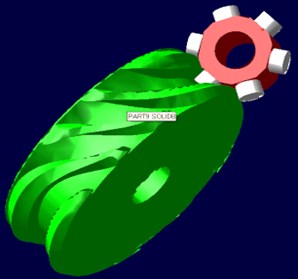
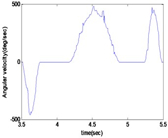
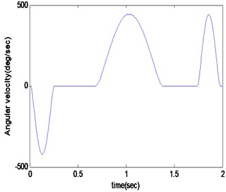
It is assumed that the radius of the roller 0. Firstly, the theoretical contour curve of the roller center is drawn in PRO/E, and then stretches symmetrically and removes the entities from the main frame of the composite cam. The offset distance is the radius of the roller, and so the accurate contour surface can be achieved shown in Fig. 4(b). Other parts of automation tool changer can be drawn relatively simply. After completing all parts of the three-dimensional model, a virtual platform of automatic tool changer was assembled, which is imported into ADAMS, and the appropriately constraints were imposed according to the relative motion among the various components. Finally, the dynamic simulation can be achieved as shown in Fig. 5(a). It can be seen that the output curves from the virtual platform contain a vibration, which will cause the acceleration mutation and occur the impact forces. So it is necessary to reduce the amplitude of the vibration in the practical processing. In contrast, the theoretical curves were shown in Fig. 5(b).
Fig. 5Output curves of the manipulator
(a)
(b)
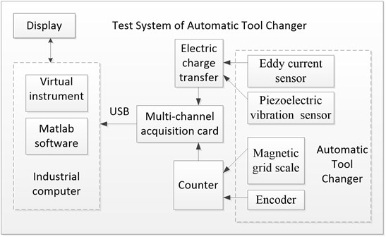
In order to further determine the dynamic characteristics of ATC, a test device is developed. The principle and composition of the test system are shown in Figure 6. The encoders are used to measure the rotating angle of the manipulator, and the magnetic grid scale is used to measure the distance of tool. Moreover, all the output TTL signals of sensors are converted to the analog voltage signals by the counter; piezoelectric vibration acceleration sensor and the eddy current micro-displacement sensor are used to measure the vibrations of the tool and manipulator, and the charge output signals are also converted into the analog voltage signals by the charge-voltage converter module; all the voltage signals are firstly scaled to the range –10~10 V by the conditioning circuit and then converted into the digital signals by the A/D converter of the MCC acquisition card. Lastly all the digital signals are transported to the industrial computer by the USB port. The testing data is processed by the software designed; a LCD screen displays the process and results of collecting data; a motor is used to control the speed of changing tool.
Fig. 6The development of test system
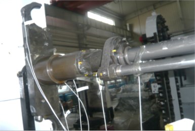
In the working conditions, the 10 vibration sensors are disposed between the power motor and the tool as shown in Fig. 7(a). The measured vibration signals take three seconds as a period time. The results are shown in Figure 7(b). It can be seen that the signals contain multiple pulse waves, and the pulse signals at each point are basically the same performances.
Fig. 7Results of the test
(a)
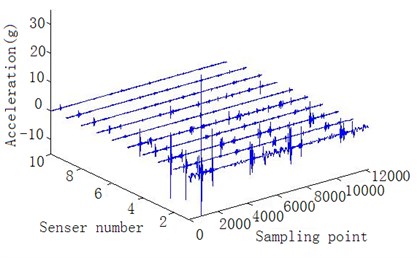
(b)
In this paper, the correlation of measured data for ATC is calculated to determine the source of vibration. In order to remove the fluctuations of local ringing effects, a sliding second-order statistical method is used to smooth the signal [22]. The obvious pulse signals 1-5 are taken as the data to calculate the correlation coefficients as the Equation (8), and the results are shown in Table 1.
where and are the means, and are the standard deviations, is the cross-correlation function.
Table 1The cross-correlation coefficients
Sensor number | 1 | 2 | 3 | 4 | 5 |
1 | 1.000 | 0.770 | 0.815 | 0.775 | 0.580 |
2 | 0.770 | 1.000 | 0.656 | 0.539 | 0.349 |
3 | 0.815 | 0.656 | 1.000 | 0.922 | 0.693 |
4 | 0.775 | 0.539 | 0.922 | 1.000 | 0.729 |
5 | 0.580 | 0.349 | 0.693 | 0.729 | 1.000 |
In Table 1, in addition to the 2nd and the 5th sensors, the correlation coefficients between the rest sensor signals are greater than 0.5, which indicates the significant positive relation between the signals. In Figure 7(b), the vibration maximum amplitude of all the sensor signals occurs at No. 1 sensor and decreases according to the order of the sensor position, which indicates that the vibration source is near the No. 1 sensor. It also can be seen that the vibration energy spreads through the transmission mechanism and decreases gradually. Based on the above analysis of correlation, it can be predicted that the vibration occurs mainly in the position of the manipulator and tool.
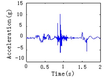
In order to strengthen the visual effect of vibration signal, the signal’s acquisition and the tool’s movement are synchronized, so the vibration signal in the manipulator position can be compared with the angle signal of encoder and the distance signal of magnetic scale at a time-based, and then you can calculate the location and posture of the tool, when the vibration occurs. By carefully checking the positional relationship among the manipulator, tool and the tool holder, the interference conditions and the cause of vibration can be determined. Taking the rotational angle of the manipulator and the vibration acceleration as the vertical axis and the time as the horizontal axis, the rotating collision is shown in Figure 8(a). Taking the horizontal distance of the manipulator and the vibration acceleration as the vertical axis and the time as the horizontal axis, the collision of slotting tool is shown in Figure 8(b).
Fig. 8Impact vibration identification
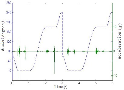
(a)
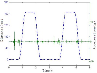
(b)
From the above Figure 8(a), it can be seen that the manipulator rotates to 0 degrees at 0.4 s and produce great impact pulse. As can be seen from Figure 8(b), the manipulator has not drawn out the tool. According to the positional relationship between the manipulator and the tool, it can be concluded that this impact is from the collision of the manipulator grasping the tool. From 1 s to 2 s in Figure 8(a), the manipulator rotates 180 degrees, but the position remains at 160 mm. In the actual condition, the manipulator and tool rotate from the one side of the spindle to the other side. During this period the splines and gears need to engage, so it can be concluded that at about 1.5 s and 4.5 s the slight vibrations are caused by the impact of spline engagement. In 0.7 s and 2.2 s, the manipulator keeps at 0° and 180° position and does not rotate, but moves along the horizontal direction. For this period the manipulator is balding in and drawing out the tool. Considering the relative positional relationship between the tool and the tool holder, it can be determined that the impacts of these two pulses are caused by the collision of the tool and tool holder. It can also be seen that the impact mainly occurs at the beginning of the actions, and next tool changing cycle begins after 3 s.
4. Optimization and improvement for the manipulator
In order to improve the stability of the tools on automatic tool changer, a new structure of the manipulator is presented. The new manipulator contains two-point locking instead of the original one-point locking. The working loads and parameters are determined by calculating and analyzing the output curves of manipulator. The new designed manipulator is verified by the simulation in a limited state. The simulation and experiment result shows that the new manipulator can increase the ability of changing tool effectively in this section.
As shown in Fig. 9(b), the manipulator of the hook knife type is used on the horizontal machining center TH6350, which is mainly composed of the arm, the finger, the locking pin, the spring and the locating pin. The motion of the manipulator can be decomposed into two actions which include rotation and translation. It is an important statement that the manipulator grasps the tool, and the forces on the tool and locking pin are analyzed in the horizontal key position.
Fig. 9Manipulator of the hook knife type
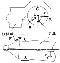
(a)
(b)
As shown in Fig. 9(a), because the outline of the tool is round, the force from the locking pin and the force from the finger point to the circle , and is the angle between and the horizon line; is the angle between and the horizon line; is the total weight of the tool and the tool shank. is the moment of grapping tool for the manipulator. In the key position, the tool will slot into the spindle, the Formula (1) is expressed according to the balance of the forces:
where is the distance from the center of the tool to the manipulator, is the inclination angle of the tool.
The ability of clamping the tool can be improved by increasing the driving force of the locking pin. But this force is applied by the internal wedge block, and its size is not easy to control. In addition, if the contact force is bigger, after the long run the contact surface is worn easily. When the speed and weight of the tool become big, the tool can't align the spindle of the machining center, because of the presence of inclination . The collision vibration amplitude will become big; the tools easily fall off; the reliability begins to become low. Thus, a method is proposed that an additional locking pin is designed to increase the force of holding tool, and thus the reliability can be improved. A large force to hold a knife can provide greater torque , which can grip heavier tools stably and ensure a very small angle , so the large vibration is avoided. Moreover, the extra quality of the manipulator arm is not necessary, which can decrease the weight and reduce the burden on the driving mechanism. Therefore a method of reducing the quality of the arm is proposed to increase the reliability of the tool changer.
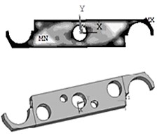
Through the analysis of the structure above, finally it is determined that the reliability and stability can be improved by designing a new structure of the manipulator. Redesign of the manipulator mainly includes two aspects, one is the topology optimization of the mechanical arm, the other is to develop locking device. The optimized volume for the mechanical arm is less than the original volume , and the stress should be within the allowable range to ensure the safety in the condition of holding a heavy knife. The mechanical stiffness is related with the topology, so that the frequency of the vibration will change with the quality decreasing. Firstly, the erasure rate in each unit is adjusted by the finite element method, and the mass distribution of the mechanical arm is determined. Then the specific shapes of removing parts are determined based on the implementation of machining. Finally, the natural frequency parameter is checked to make sure it is outside the resonance district. The constraints of topology variables are shown as follows:
Ansys software can achieve the static topology optimization based on dynamic stiffness and the dynamic topology optimization based on the frequency characteristics [23-24]. The finite element model of the manipulator’s arm is simplified as follow:
1) The screw holes and the small attached parts are removed in the model.
2) The rotational center of the manipulator is set to the fixed constraints, and the heavy torque and gravity are applied to the fingers.
3) The thickness of the manipulator is small relative to the width and length, so the topology optimization is in only the two-dimensional plane for the arm. And the outside borders and fingers are not optimized.
The unit solid 95 in Ansys is chosen to mesh for the model. According to the provisions of Ansys, the number 1 area can be optimized, and the number 2 area cannot be optimized. In the actual work the fingers at mechanical arm’s ends need to hold the tools in turn or simultaneously, so the optimized model is a centrosymmetric structure. By the Topological Opt module, the white areas indicate lower density, which can be removed. After removing the mass, the shape of the mechanical arm is shown in Figure 10(a).
Fig. 10New manipulator
(a)
(b)
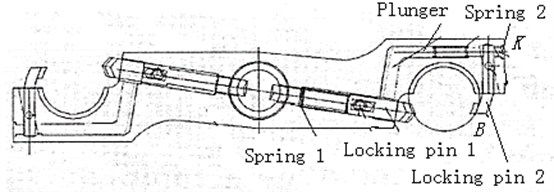
After the topology optimization of the mechanical arm, the locking device is developed to increase the ability of grasping tool for the mechanical fingers. As shown in Fig. 10(b), the new manipulator is presented, which has two locking devices. A plunger is installed in the manipulator, which is fixed on the locking pin 1. The plunger presses the locking pin 2 by the level movement. The energy storage spring 2 is installed between the finger and the locking pin 2, which also ensures that the locking pin 2 keep open on the point all the time when the plunger retracts. According to the analysis of the tool in Fig. 10(a), the point of the new structure will be below the old position, so the angle will become bigger. From the Formula (9), it can be obtained that the force and the contact force will be smaller, when the weight of the tool is a constant. The locking pin 2 can be seen as the extension of the finger, which increases the wrap angle of the finger. Even if a small amount of wear occurs, the tool can't also fall off as a result of the wrap angle 270 degree. In summary, in the same conditions the new manipulator can carry the heavier tool stably than the old.
In the tool-changing process, the actions of the new manipulator are presented as follows. When the manipulator is empty, the locking pin 2 is open under the action of the energy storage spring 1 and 2, and the locking pin 1 retracts. When the manipulator grasps the tool, the trapezoid groove of the finger and the trapezoid groove of the tool shank completely contact, and the wedge block in the axis of the manipulator drives the plunger out, and the locking pin press the tool shank tightly. In the tool-loosing process, the action’s sequence is the opposite of grasping the tool. Firstly, the wedge block releases, and the locking pin 1 and the plunger retract. Then, the locking pin 2 is open under the action of the energy storage spring 2. Finally, the tool moves off the finger.
In order to prove the advantages of the new manipulator, a three-dimensional model is built and simulated in the following three conditions by Adams.
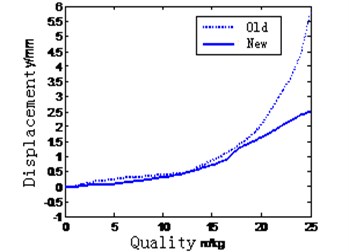
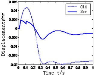
During the rotational process, the biggest force of the tool is the sum of the centrifugal force and gravity, and the direction is –90 degree. The parameters of the manipulator: 165 mm, –90 degree. The quality of the tool is from 0 kg and 25 kg. In above conditions the maximum displacement of the tool is received by the simulation. As can be seen in Fig. 11(a), the ability of preventing tool falling is improved less with the light tool, but more with the weight tool.
Fig. 11Data of collision
(a)
(b)
(c)
(d)
In the tool-slotting process, the tool contacts the spindle hole of the machining center, the impact will be generated by the collision. The impact is 100 N in the axial direction of the tool. The parameters of the manipulator: 15 mm, 0 degree. The quality of the tool is 25 kg. In above conditions the displacement of the tool is received during 1 s by the simulation. As can be seen in Fig. 11(b), the tool return to the initial position faster and the peak is smaller. So the ability of resisting the impact is improved more.
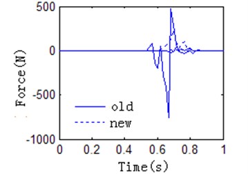
The optimized manipulator is simulated in the simulation platform. It can see that the collision force are significantly reduced in Figure 11(c). Testing by the experiment platform for improved manipulator, the testing results in Figure 11(d) also indicate that the oscillation amplitude decreases, and the reliability and stability of the manipulator are improved.
5. Conclusions
Automation tool changer is widely used in the machining industry, which can improve the processing speed and reduce human labor. But the reliability and stability of the tool changer have been the key issue to restrict this improvement of the performance for automation tool changer, especially in high-speed and large-mass occasions. In this paper, a horizontal tool changer was taken as example, whose motion law and dynamic characteristics were studied. The dynamic equations were established, and the virtual platform was built. The force status for the tool changer was analyzed, and a vibration phenomenon was found. Further, in order to identify and find the vibration source, a testing platform was built. The testing analysis showed that the vibration comes mainly from the collision, and the tool cannot be held firmly for the manipulator. An optimization method for the manipulator is proposed to increase the ability of holding tool. Finally, the simulation and experimental proved that the improved manipulator can effectively reduce the vibration amplitude and improve the stability of changing tool. However, in order to ensure the perfect ability for automation tool changer under greater loads, other parts of automation tool changer device also need to be analyzed and optimized in the future.
References
-
Christian Brecher, Sven C. Lange, Frank Niehaus, Christian Wenzel Automated tool exchange for ultraprecision diamond milling and turning applications. The second International Conference on Multi-Material Micro Manufacture, 2006, p. 63-66.
-
Diana C. W. Friedman, Jesse Dosher, Tim Kowalewski, Jacob Rosen, Blake Hannaford Automated tool handling for the trauma pod surgical robot. IEEE International Conference on Robotics and Automation Roma, Italy, 2007.
-
S. Balestra, A. Bertolin, C. Bozza A fast automatic plate changer for the analysis of nuclear emulsions. Nuclear Instruments and Methods in Physics Research, Vol. 716, 2013, p. 96-100.
-
Han Yue-mei Analysis and development of automatic tool changer. Equipment Manufacturing Technology, 2010, p. 128-129.
-
Shen Guixiang, Ding Ye, Zhang Yingzhi, Gu Dongwei, Liang Dong, Chen Bingkun Failure analysis of tool changer system based on cloud model. Journal of Central South University (Science and Technology), Vol. 44, Issue 4, 2013, p. 1420-1424, (in Chinese).
-
Lu Xiaohong, Han Pengzhuo, Wu Wenyi, Wei Jie Reliability evaluation of circular tool magazine and automatic tool changer. Advanced Materials Research, Vol. 630, 2013, p. 245-248.
-
Jeong Y. H., Tae H., Min B. K., Cho D. W. Virtual automatic tool changer of a machining centre with a real-time simulation. International Journal of Computer Integrated Manufacturing, Vol. 21, Issue 8, 2008, p. 885-894.
-
Xiong Zhuang, Yin Yanchao, Yan, Yilong The macro program design and digital simulation of the automatic tool changer for 5-axis Machine. Advanced Materials Research, Vol. 655-657, 2013, p. 1282-1285.
-
Mustafa Ilhan Goklert, Murat Bjlgjn K. Design of an automatic tool changer with disc magazine for a CNC horizontal machining center. International Journal of Machine Tools and Manufacture, Vol. 37, Issue 3, 1997, p. 277-286.
-
Liu Jing Double CAM linked automatically change the tools of technology. Dalian University of Technology, 2008.
-
J. Liu The research of dual-cam linkage automatic tool changer technology. MS, Journal of Dalian University of Technology, China, 2008, p. 39.
-
Linxia Liao, Jay Lee Design of a reconfigurable prognostics platform for machine tools. Expert Systems with Applications, Vol. 37, Issue 1, 2010, p. 240-252.
-
David Gyimothy, Andras Toth Experimental evaluation of a novel automatic service robot tool changer. IEEE/ASME International Conference on Advanced Intelligent Mechatronics Budapest, Hungary, 2011.
-
Lu Xiaohong, Han Pengzhuo, Wu Wenyi, Wei Jie Reliability evaluation of circular tool magazine and automatic tool changer. Advanced Materials Research, Vol. 630, 2013, p. 245-248.
-
Zhang Lianzhong, Wang Li Machining center automatic atc analysis and research. International Conference on Information Management, Innovation Management and Industrial Engineering (ICIII), 2010, p. 355-358.
-
Guo Xiao-lan, Zhou Xin-min, Cui Tao Finite element modeling of automatic tool changer and dynamic characteristics analysis of ATC TH6350 bed machining center. Journal of Southwest Forestry College, Vol. 26, Issue 2, 2006, p. 76-79.
-
Kim Jae-Hyun, Lee Choon-Man Multi-stage optimum design of magazine type automatic tool changer arm. Journal of Central South University of Technology, Vol. 19, Issue 1, 2012, p. 174-178.
-
Wang Zhen-yu, Jiang Chong-min, Li De-xiu Fast and reliable the tool changer. Design and Calculation, Issue 4, 2006, p. 132-133.
-
Angeles J. Optimization of Cam Mechanisms. Kluwer Academic, Dordrecht, 1991, p. 45.
-
Jiang Xiuming Analysis and design of conjugate cam shedding mechanism with dual driving shafts. Journal of Dong Hua University, Vol. 15, Issue 1, 1998, p. 57-60.
-
Lo Jie-Shing, Tseng Ching-Haun, Tsay Chung-Biau Non-undercutting conditions of roller gear cams. Transactions of the Canadian Society for Mechanical Engineering, Vol. 26, Issue 4, 2003, p. 413-434.
-
Bimbot Frederic, Margin-Chagnolleau Ivan, Mathan Luc Second-order statistical measures for text-independent speaker identification. Speech Communication, Vol. 17, Issue 1-2, 1995, p. 177-192.
-
Liu Y. D., Bian G. A study of structural topology optimization based on ANSYS. Proceedings of the 10th International Conference on Civil, Structural and Environmental Engineering Computing, Civil-Comp, 2005.
-
Silva Emilio Carlos Nelli, Nader Gilder, Shirahige Alessandro Barbosa, Adamowski Julio Cezar Characterization of novel flextensional actuators designed by using topology optimization method. Journal of Intelligent Material Systems and Structures, Vol. 14, Issue 4-5, 2003, p. 297-308.
About this article
The authors would like to thank Science and Technology Major Project of China (Grant No. 2011ZX04011-022) for the research.
